
1. Why is it necessary to measure program execution time?
Rather than measuring program execution time, it might be more accurate to refer to it as measuring task execution time. The projects we undertake are aimed at achieving specific objectives, thus completing corresponding tasks. Simple projects typically focus on a single task, while more complex ones involve multiple tasks interacting to achieve project goals. Therefore, when designing a product feature, it is essential to consider its system response speed. However, when hardware is sufficiently fast, the response speed of each software task determines the effectiveness of the product functionality.
The timeliness of software dictates the speed of the system, and this statement holds true under the premise of not considering hardware limitations. However, for most of our projects, the real limiting factor for system response speed is still hardware resources. For example, the AD sampling chip, which serves as the window between the real world and the digital world, requires us to perceive external feedback to make correct decisions for our system. Thus, the conversion speed of the AD chip becomes crucial in determining the speed of that feedback, which in turn affects our system. (This does not include some predictive algorithms that allow the system to make judgments and actions in advance.)
Excluding hardware limitations, the program execution time becomes a key factor affecting system speed. Most of our tasks generally adopt a polling or monitoring state. If the tasks we need to process occupy too much CPU time, it results in delays for the entire system, especially in a multitasking scheduling system like RTOS, where sometimes we overlook the fact that the execution time of tasks is too long, leading to the system never achieving our expected results. Therefore, we need to clearly understand how long our tasks actually run.
So, you might ask, how do we measure execution time? If we measure based on the essence of program execution, we need to consider: (the longest number of instructions executed by the program*the instruction execution cycle of the chip = the actual longest time our program runs), but we generally do not require such precise data (which may not even be accurate due to clock discrepancies). At least for most projects, this is not very meaningful and is time-consuming. We typically measure the entire time span from start to finish, which is more measurable and usable. Below, I summarize the measurement methods used in my daily work and research for your reference and learning.
2. Essential IO Toggle Oscilloscope Measurement Method for Engineers
This method is commonly used by most engineers. In the laboratories of most embedded R&D companies, there are very precise oscilloscopes. We usually only need to set the IO port to high at the start of the program and reset it to low at the end of the program. The duration of the high signal displayed on the oscilloscope represents our program execution time.
Reference code is as follows:
/*******************************************
 * Function : sControlTask
 * Author: (WeChat: Last Bug)
 *******************************************/
void sControlTask(void)
{
 //1. Set Test pin to high
    SetTEST_IO_HIGTH();
 //2. Perform ADC sampling
    sADC_Sample();
 //3. Get sensor value
    sGetAnalogVal();
 //4. Controller calculation processing
    sContrlCal();
 //5. Set Test pin to low
    SetTEST_IO_LOW();
}
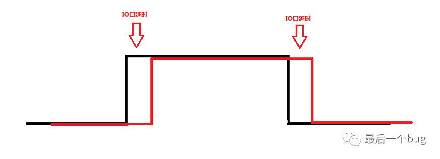
Note:The oscilloscope method is a commonly used method. Some may wonder if toggling the IO port introduces delays. In fact, the action delay of the IO port does not affect our measurement of program time, especially since the time required for the IO action is negligible compared to the task time, as illustrated in the following diagram:
Although the oscilloscope measurement does not introduce significant delays, our tasks are dynamic, and the width of the high and low signals we test may vary, making it difficult to visually identify the longest execution time on the oscilloscope. This is the only drawback, but for most projects, such precision is not required; this metric serves merely as a reference in program design.
3. Essential IO Capture Measurement Method for Engineers
This method is similar to the oscilloscope method and also falls under external measurement methods. However, the advantage of this method is that it can compensate for the difficulty in identifying the longest time due to significant variations in task execution time.
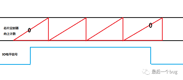
General implementation idea:We can treat the IO toggle signal as a pulse width for measurement. By programming another high-end chip or a chip with a higher clock frequency, we can use the capture function combined with a timer to record the time. This way, we can obtain the program execution time and, through programming, calculate the maximum and average pulse widths over a period to better represent the program’s execution status.
The drawback of this method: The accuracy of this method depends on the external chip, but it is sufficient for most applications.
Below is pseudocode for your reference:
/*******************************************
 * Function : EcapInterrupt
 * Description : Capture interrupt trigger
 * Author : (WeChat: Last Bug)
 *******************************************/
void EcapInterrupt(void)
{
    //Captured rising edge
    if(GET_Ecap_Statue(ECAP1) == ECAP_RISE)
    {
        //1) Start recording pulse width
        //2) Get timer count time
        //3) Set ECAP to capture falling edge mode
    }
    //Captured falling edge
    else if(GET_Ecap_Statue(ECAP1) == ECAP_FALL)
    {
        //1) End recording pulse width
        //2) Get timer count time
        //3) Calculate pulse width time or final result
        //4) Process related data
        //5) Set ECAP to capture falling edge mode
    }
}/*******************************************
 * Function : TimerInterrupt
 * Description : Rising count timer period trigger
 * Author : (WeChat: Last Bug)
 *******************************************/
void TimerInterrupt(void)
{
    //If already in pulse width detection, accumulate time;
    //If not in pulse width detection, do nothing.
}
Calculating pulse width using a timer:
The formula for obtaining the pulse width (i.e., program execution time) is as follows:
Pulse Width = Timer Time * Trigger Count + (Falling Edge Timer Count – Rising Edge Timer Count) * Timer Base
4. Essential Internal Timer Method for Engineers
This method is similar to the IO capture method. In embedded systems, we often encounter the use of timestamps, which can also provide CPU utilization. The method is essentially the same; the system will enable a core timer, which is generally unaffected by external interference. By inserting markers at the beginning and end of the task using this timer, we can obtain the timer count during that period and calculate the program execution time.
This method is not commonly used on our small or resource-constrained chips because we rarely have spare timers for additional processing. Additionally, since timer processing requires some time and involves extra calculations, it can lead to measurement time errors. If the error is within an acceptable range, this method can still be used.
5. Essential Emulator Method for Engineers
Currently, many chip debugging emulators have the capability to measure various performance aspects of the simulation program. For instance, KEIL or CCS integrated development environments generally support measuring program execution time, typically measuring the time between breakpoints. Users need to configure parameters such as the current crystal oscillator and clock frequency in the development environment to obtain a runtime result.
However, based on feedback from many engineers, some emulators may have significant measurement errors. These errors may arise from user configuration issues or from the inherent algorithmic mechanisms of the emulator itself. It is necessary to understand the emulator’s calculation methods, which will not be elaborated here. It is recommended to use Method 1 first, and if resources allow, Method 2 can be adopted.
That concludes today’s summary. Here is the WeChat account: “Last Bug”. Thank you all for your attention, and I will have more exquisite articles for you to read in the future! I also hope everyone shares and forwards!
Recommended Reading
Common Program Framework for Microcontrollers: Time-Sliced Polling (Detailed Code Annotations)
Dynamic Interface Technology in Embedded Programming (Experience Insights)
Are You Sure You Know How to Use the Watchdog? (Full of Experience Insights)
Memory-Saving Techniques in Microcontroller Development (C Language Version)
A “Super Strong” Queue Implementation in C Language (With Code)
Everything You Need to Know About CRC Check in Communication Protocols (With Code)
[Serial] Embedded Test-Driven Development (9)