Disclaimer: Some images in this article are sourced from the internet. Please contact us for removal if there are any copyright issues.
Are you still using delay() to block your system? To achieve true concurrent tasks, mastering timers and counters is essential—they are the soul of MCU task scheduling. This article will take you from the underlying hardware to advanced applications like PWM, thoroughly understanding this “time machine” duo, bidding farewell to inefficiency and becoming a true embedded expert.
Core Concepts: Timer vs. Counter
Timer
Definition: A device that generates periodic or one-time signals at specified time intervals.
Usage: Measures the time between external hardware events. In embedded systems, it is commonly used to trigger events or interrupts at fixed intervals, for updating displays, measuring the interval of button presses, creating delays, and other tasks.
Counter
Definition: A device that increments a count value for each occurrence of an event.
Usage: In embedded systems, it is used to record the number of times an event occurs, such as counting button presses, the number of motor rotations, or the number of data packets received over a network.
Both software and hardware can implement timers and counters, depending on system requirements. For high-precision timers, implementing them in software can be very cumbersome. Therefore, timers and counters are standard peripherals in almost all microcontrollers.
Timers measure time by countingperiodic clock signals; counters countasynchronous external events. Essentially, a timer is a special counter that counts fixed frequency events, with the main difference being the clock/signal source.
Hardware Basics: Shared Core Circuits
Inside a microcontroller (MCU), the core of the timer peripheral is aCounter Register. There are various types of timers in microcontrollers, all based on the same core principle, but offering different levels of functionality.
The basic structure of timers and counters is similar, sharing similar core circuits.
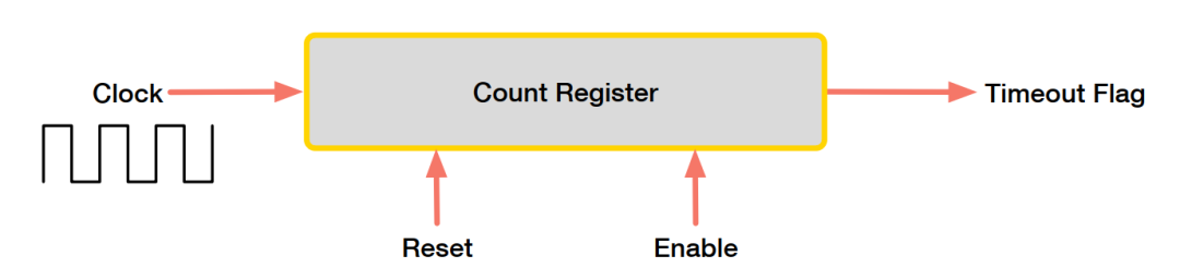
How does the above work?
The core is a count register (Count Register), which increments its value by one when an event occurs at the Clock input. It can be said that the signal at the Clock input drives the counter. The count register starts from zero and continuously accumulates its value when Clock events occur. When the register reaches its maximum value, it overflows and starts counting from zero again.
This overflow event signifies the timer’s “timeout.” The maximum value of this register depends on its width; for example, if the register is 8 bits wide, the counter will count from 0 to 2^8 – 1 = 255 before resetting. At any time, the processor core should be able to read the value in the count register.
Driven by the clock signal, the count register accumulates from 0, and upon reaching the maximum value, it willoverflow and reset to zero. This overflow event is key to timing.
The reset and enable signals in the count register are control signals that allow the processor core to reset the count value to zero and start counting.
The main difference between counters and timers lies in the Clock input. If the Clock is connected to a synchronous periodic clock signal, this circuit operates as a timer; if the Clock is connected to an asynchronous event-based signal (like a button press), then this circuit operates as a counter.
The purpose of a timer is to “time” the duration between events, while a counter is to “count” the number of occurrences of events. Essentially, a timer is also a counter that counts periodic clock events. For example, consider the opening and closing of a smart door: the counter’s function is to count how many times the door has been opened, while the timer’s function is to record how long the door remains open.
Enhanced Features: From Basics to Advanced
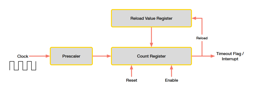
Microcontrollers often add several features on top of the basic circuitry, some of which include:
- Interrupts
The basic structure above does not notify of value overflow events, but by polling the timer register in software, one can determine if an overflow has occurred. Therefore, timer peripherals add interrupt hardware to notify such overflow events.
- Auto Reload
In the basic structure above, counters and timers count up from 0. If timing a shorter event, the starting value does not necessarily have to be 0.
The auto-reload feature adds a reload register that allows the use of a custom starting value. This means that once an overflow occurs, the timer will automatically reload this custom starting value and begin counting up from it.
- Clock Source Configuration
In timers, the frequency of the clock determines the speed of timer overflow. In other words, if we want to time a shorter period, we need to lower the clock frequency.
Microcontrollers often provide configurations to slow down the clock frequency through aprescaler register. The prescaler register divides the input clock by setting a value, which is typically a power of 2, such as 2, 4, 8, 16, etc. For example, if the input clock is 60MHz and the prescaler value used is 8, then the timer clock is 60MHz/8.
- Upcounting/Downcounting
Some microcontrollers provide the ability to choose whether the timer counts up or down.
- Cascading Counters
If only hardware is used to time longer events, a single register is insufficient, so some controllers provide cascading timer registers to offer longer timeout values. For example, two 8-bit counter registers can be cascaded into a single 16-bit counter register.
Operating Modes: Diverse Application Methods
- One-shot Mode
The timer counts up or down only once until it overflows and stops. This mode is useful for generating a single pulse.
- Continuous Mode
The timer will continuously count up or down. This mode is useful for measuring the duration of events without a clear start or end.
- Input Capture
Allows the timer to capture the counter’s value based on a hardware input event. Commonly used to measure the duration or frequency of hardware input signals.
We can think of it as a stopwatch with a “snapshot” feature. This stopwatch (timer) runs in the background, counting, but it is connected to an external “button” (a GPIO pin). When the “button” is pressed (i.e., a signal appears on the pin, such as a level change from low to high), the timer immediately records the current count value and stores it in a dedicated register, but the stopwatch itself does not stop; it continues running.
Hardware Input Event is the action that triggers the “snapshot.” The most common events are the “edges” of digital signals, i.e., changes in voltage levels. For example, when a sensor signal transitions from low to high, we call it a “rising edge”; conversely, it is a “falling edge.” The input capture function is used to accurately capture the moments these events occur.
- Output Compare
When output compare is enabled, the timer often has one or more dedicated output pins. The timer can be configured to generate an output signal on these pins when its count value matches a specified comparison value. This comparison value is typically stored in a compare register. Output compare can be seen as a mode for generating hardware-based waveforms.
- Pulse Width Modulation (PWM)
PWM is a hardware waveform generation mode that is very similar to output compare, but PWM is a special type of waveform.
Key Formulas
The resolution of a timer (in units: bits/second) indicates the time required for the counter to increment by 1, which is the reciprocal of the timer’s clock frequency.
When determining a count value to load for a desired timeout duration, the formula is as follows:
Where is the timeout duration in seconds, is the timer resolution or input clock period (the reciprocal of frequency), and count is the count value.
Specific Implementation: Timer Peripheral in ESP32-S3
The ESP-S3 includes four different timers: general-purpose timer, system timer, watchdog timer, and XTAL32K watchdog timer. The system timer and watchdog timer are mainly used internally within the device.
System Timer: The ESP32-S3 has a built-in 52-bit system timer, primarily providing heartbeat pulses for the operating system or generating periodic or one-time interrupts as a general-purpose timer.
General Purpose Timers: The ESP32-S3 has four built-in 54-bit general-purpose timers, each with a 16-bit prescaler and a 54-bit auto-reload up/down timer. They are used for precise timing and can also trigger interrupts.
Watchdog Timers: Used to monitor whether the system has crashed and to automatically recover. The ESP32-S3 has three watchdog timers: one in each of the two timer groups (referred to as the main system watchdog timer, abbreviated as MWDT) and one in the RTC module (referred to as the RTC watchdog timer, abbreviated as RWDT). During the bootloader flash firmware process, the RWDT and MWDT in timer group 0 are automatically enabled to detect errors occurring during the boot process and recover operation.
XTAL32K Watchdog Timer: Specifically used to monitor the 32KHz low-speed crystal oscillator. When the XTAL32K_CLK is detected to have stopped oscillating, it will trigger a stop oscillation interrupt RTC_XTAL32K_DEAD_INT, waking the CPU if it is in Light-sleep or Deep-sleep state.
Welcome to “Like” “Follow” and “Share”
Feel free to leave your footprints in the comments!