“ The MCPWM of ESP32-S3 is a multifunctional PWM generator, consisting of two units, supporting 12 independent PWM outputs. It achieves high-precision control through modules such as timers and operators, and features dead time and carrier modulation functions, with fault detection and braking protection capabilities. It allows flexible GPIO output configuration and is widely used in motor control, digital power supplies, and other scenarios, providing efficient solutions for power electronics applications.”
01
—
MCPWM Overview
The MCPWM (Motor Control Pulse Width Modulator) of ESP32-S3 is a multifunctional PWM generator, widely used in motor control, digital power supplies, LED dimming, and other scenarios. It achieves high-precision and high-efficiency PWM signal output through multiple timers, operators, comparators, and generator modules, and supports advanced features such as fault detection, synchronous control, and pulse width capture.
1. Features
-
Rich functionality: Supports various motor control modes, such as forward/reverse driving, power-off braking, etc.
-
High-precision control: Supports dead time control and external signal capture.
-
Multi-channel output: Each MCPWM peripheral can output 6 PWM signals, and two MCPWM peripherals can output a total of 12 PWM signals.
-
Advanced features: Supports carrier modulation, fault detection, and braking control.
-
Flexible configuration: Each PWM operator can use the timing reference of any PWM timer, and different PWM operators can use the same or different PWM timer values to generate PWM signals.
2. Quantity
The ESP32-S3 contains two MCPWM units, each with three pairs of PWM outputs. Each MCPWM unit includes a clock divider, three PWM timers, three PWM operators, and a capture module. Therefore, the two MCPWM units can provide a total of 12 independently adjustable PWM outputs.
3. IO Pin Requirements
The MCPWM module consists of two sub-modules (MCPWM0 and MCPWM1), each of which can configure multiple operators (OP0, OP1, OP2), and each operator can output to different GPIO pins. Each operator supports two output channels (A and B), and each channel can be mapped to multiple GPIO pins. For example, the A channel of the OP0 operator of the MCPWM0 module can output to GPIO0, GPIO10, or GPIO16. All available IO pins are shown in the table below:
|
MCPWM Module |
Operator |
Output Channel |
Optional GPIO (Example) |
|
MCPWM0 |
OP0 |
A |
GPIO0, GPIO10, GPIO16 |
|
OP0 |
B |
GPIO1, GPIO11, GPIO17 |
|
|
OP1 |
A |
GPIO2, GPIO12, GPIO18 |
|
|
OP1 |
B |
GPIO3, GPIO13, GPIO19 |
|
|
OP2 |
A |
GPIO4, GPIO14, GPIO20 |
|
|
OP2 |
B |
GPIO5, GPIO15, GPIO21 |
|
|
MCPWM1 |
OP0 |
A |
GPIO6, GPIO25, GPIO33 |
|
OP0 |
B |
GPIO7, GPIO26, GPIO34 |
|
|
OP1 |
A |
GPIO8, GPIO27, GPIO35 |
|
|
OP1 |
B |
GPIO9, GPIO28, GPIO36 |
|
|
OP2 |
A |
GPIO22, GPIO29, GPIO37 |
|
|
OP2 |
B |
GPIO23, GPIO30, GPIO38 |
02
—
Functional Block Diagram
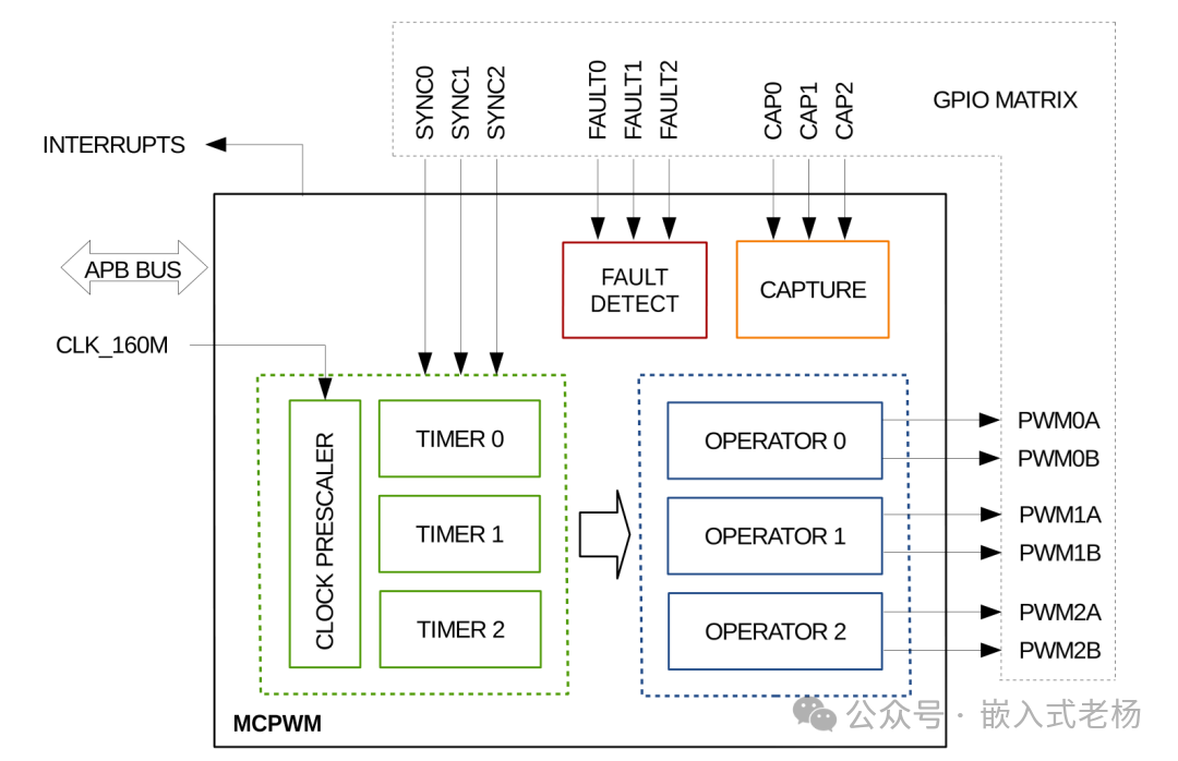
In the MCPWM module of ESP32-S3, the workflow for generating PWM signals with dead time and carrier modulation is as follows:
① The clock prescaler (ClockPrescaler) divides the input CLK_160M clock signal to provide an appropriate clock frequency for the timers. Then, three timers (Timer0, Timer1, Timer2) count based on the divided clock signal to generate the base period of the PWM signal.
② The operators (Operator0, Operator1, Operator2) generate PWM signals based on the outputs of the timers and configuration parameters. The operators can configure dead time to insert a fixed time interval between two PWM signals, preventing both signals from being on simultaneously.
③ The operators can also use carrier modulation technology to combine the PWM signal with a high-frequency carrier signal, generating a high-frequency PWM signal to improve the precision and efficiency of motor control. Finally, the generated PWM signal is output to the corresponding GPIO pins through the GPIO matrix to drive external devices.
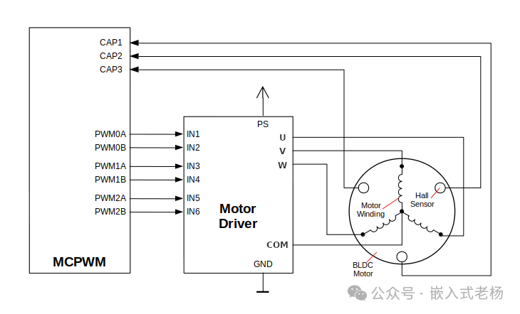
④ The fault detection (FaultDetect) module monitors the operating status of the MCPWM, and the capture module is used to capture the rising or falling edge of external signals to achieve more complex control logic. In the brushless DC motor (BLDC) scheme shown below, the capture sub-module can be used to confirm the rotor position from the Hall sensor.
Dead Time:
In motor control, dead time is a safety time interval set in the design of power circuits (such as H-bridges and three-phase inverters) to prevent the upper and lower power devices of the bridge arm from being on simultaneously. When the control signal switches from one bridge arm to another, due to the switching delay characteristics of the devices, if there is no dead time, there may be a brief state where both upper and lower devices are on, leading to a short circuit. Dead time is achieved by inserting delay times (positive edge delay and negative edge delay) at the rising and falling edges of the original control signal, ensuring that the upper device is completely off before the lower device turns on, or the lower device is completely off before the upper device turns on, thus avoiding the risk of bridge arm short circuit and protecting the safety and stable operation of power devices and circuit systems.

The MCPWM module has the following peripherals:
Clock Prescaler Frequency (ClockPrescaler):
The clock prescaler is used to reduce the input clock frequency (CLK_160M) to meet the needs of PWM generation. It adjusts the clock frequency through a division factor to provide an appropriate clock signal for subsequent timers.
Timer:
The timer is the core part of MCPWM, used to generate timing signals. Each timer can be independently configured, including period, comparison values, etc.
Operator:
The operator receives timing signals from the timer and generates PWM signals based on the configuration. Each operator can be configured for different PWM modes, such as complementary, bridging, etc.
Fault Detection (FaultDetect):
The fault detection module is used to monitor the operating status of the MCPWM and detect possible fault conditions, such as overcurrent, overvoltage, etc.
Capture:
The capture module is used to capture the rising or falling edge of external signals, typically used to measure the period or frequency of external signals.
GPIO Matrix:
The GPIO matrix is used to output the PWM signals generated by MCPWM to specified GPIO pins.
03
—
MCPWM Various Mode Usage Methods
1. Classic PWM Waveform Generation
Programming Process:
Create a timer group, configure the timer’s clock source, resolution, period, counting mode, and other parameters.
Create an operator and bind it to the timer.
Create a comparator and set the comparator’s comparison value.
Create a generator and configure the generator’s GPIO pin.
Set the actions of the generator on timer events and comparator events to generate the desired PWM waveform.
#include "driver/mcpwm.h"
#include "esp_log.h"
#define MCPWM_GROUP_ID 0
#define MCPWM_TIMER_ID 0
#define MCPWM_GEN_A_GPIO 21
#define MCPWM_GEN_B_GPIO 22

void app_main(void) {
    // Create timer
    mcpwm_timer_handle_t timer = NULL;
    mcpwm_timer_config_t timer_config = {
        .group_id = MCPWM_GROUP_ID,
        .clk_src = MCPWM_TIMER_CLK_SRC_DEFAULT,
        .resolution_hz = 1000000, // 1MHz
        .period_ticks = 1000, // 1ms period
        .count_mode = MCPWM_TIMER_COUNT_MODE_UP,
    };
    ESP_ERROR_CHECK(mcpwm_new_timer(&timer_config, &timer));

    // Create operator
    mcpwm_oper_handle_t oper = NULL;
    mcpwm_operator_config_t oper_config = {
        .group_id = MCPWM_GROUP_ID,
    };
    ESP_ERROR_CHECK(mcpwm_new_operator(&oper_config, &oper));

    // Bind timer and operator
    ESP_ERROR_CHECK(mcpwm_operator_connect_timer(oper, timer));

    // Create comparator
    mcpwm_cmpr_handle_t cmpr_a = NULL;
    mcpwm_comparator_config_t cmpr_config = {
        .flags.update_cmp_on_tez = true,
    };
    ESP_ERROR_CHECK(mcpwm_new_comparator(oper, &cmpr_config, &cmpr_a));
    ESP_ERROR_CHECK(mcpwm_comparator_set_compare_value(cmpr_a, 500)); // 50% duty cycle

    // Create generator
    mcpwm_gen_handle_t gen_a = NULL;
    mcpwm_generator_config_t gen_config = {
        .gen_gpio_num = MCPWM_GEN_A_GPIO,
    };
    ESP_ERROR_CHECK(mcpwm_new_generator(oper, &gen_config, &gen_a));

    // Set generator actions
    ESP_ERROR_CHECK(mcpwm_generator_set_action_on_timer_event(gen_a, MCPWM_GEN_TIMER_EVENT_ACTION(MCPWM_TIMER_DIRECTION_UP, MCPWM_TIMER_EVENT_EMPTY, MCPWM_GEN_ACTION_HIGH)));
    ESP_ERROR_CHECK(mcpwm_generator_set_action_on_compare_event(gen_a, MCPWM_GEN_COMPARE_EVENT_ACTION(MCPWM_TIMER_DIRECTION_UP, cmpr_a, MCPWM_GEN_ACTION_LOW)));

    // Start timer
    ESP_ERROR_CHECK(mcpwm_timer_enable(timer));
    ESP_ERROR_CHECK(mcpwm_timer_start_stop(timer, MCPWM_TIMER_START_NO_STOP));
}
2. Dead Time Generation
Programming Process:
Create a dead time module and bind it to the operator.
Configure the dead time, including the rising edge dead time and falling edge dead time.
Set the actions of the generator on timer events and comparator events to generate PWM waveforms with dead time.
#include "driver/mcpwm.h"
#include "esp_log.h"
#define MCPWM_GROUP_ID 0
#define MCPWM_TIMER_ID 0
#define MCPWM_GEN_A_GPIO 21
#define MCPWM_GEN_B_GPIO 22

void app_main(void) {
    // Create timer
    mcpwm_timer_handle_t timer = NULL;
    mcpwm_timer_config_t timer_config = {
        .group_id = MCPWM_GROUP_ID,
        .clk_src = MCPWM_TIMER_CLK_SRC_DEFAULT,
        .resolution_hz = 1000000, // 1MHz
        .period_ticks = 1000, // 1ms period
        .count_mode = MCPWM_TIMER_COUNT_MODE_UP,
    };
    ESP_ERROR_CHECK(mcpwm_new_timer(&timer_config, &timer));

    // Create operator
    mcpwm_oper_handle_t oper = NULL;
    mcpwm_operator_config_t oper_config = {
        .group_id = MCPWM_GROUP_ID,
    };
    ESP_ERROR_CHECK(mcpwm_new_operator(&oper_config, &oper));

    // Bind timer and operator
    ESP_ERROR_CHECK(mcpwm_operator_connect_timer(oper, timer));

    // Create dead time module
    mcpwm_deadtime_handle_t deadtime = NULL;
    mcpwm_deadtime_config_t deadtime_config = {
        .update_on_tez = true,
        .update_on_tep = true,
        .update_on_sync = true,
        .deadtime_ticks = 10, // 10us dead time
    };
    ESP_ERROR_CHECK(mcpwm_new_deadtime(oper, &deadtime_config, &deadtime));

    // Create comparator
    mcpwm_cmpr_handle_t cmpr_a = NULL;
    mcpwm_comparator_config_t cmpr_config = {
        .flags.update_cmp_on_tez = true,
    };
    ESP_ERROR_CHECK(mcpwm_new_comparator(oper, &cmpr_config, &cmpr_a));
    ESP_ERROR_CHECK(mcpwm_comparator_set_compare_value(cmpr_a, 500)); // 50% duty cycle

    // Create generator
    mcpwm_gen_handle_t gen_a = NULL;
    mcpwm_generator_config_t gen_config = {
        .gen_gpio_num = MCPWM_GEN_A_GPIO,
    };
    ESP_ERROR_CHECK(mcpwm_new_generator(oper, &gen_config, &gen_a));

    // Set generator actions
    ESP_ERROR_CHECK(mcpwm_generator_set_action_on_timer_event(gen_a, MCPWM_GEN_TIMER_EVENT_ACTION(MCPWM_TIMER_DIRECTION_UP, MCPWM_TIMER_EVENT_EMPTY, MCPWM_GEN_ACTION_HIGH)));
    ESP_ERROR_CHECK(mcpwm_generator_set_action_on_compare_event(gen_a, MCPWM_GEN_COMPARE_EVENT_ACTION(MCPWM_TIMER_DIRECTION_UP, cmpr_a, MCPWM_GEN_ACTION_LOW)));

    // Start timer
    ESP_ERROR_CHECK(mcpwm_timer_enable(timer));
    ESP_ERROR_CHECK(mcpwm_timer_start_stop(timer, MCPWM_TIMER_START_NO_STOP));
}
3. Carrier Modulation
Programming Process:
Create a carrier module and bind it to the operator.
Configure carrier frequency, duty cycle, and other parameters.
Set the actions of the generator on timer events and comparator events to generate carrier-modulated PWM waveforms.
#include "driver/mcpwm.h"
#include "esp_log.h"
#define MCPWM_GROUP_ID 0
#define MCPWM_TIMER_ID 0
#define MCPWM_GEN_A_GPIO 21
#define MCPWM_GEN_B_GPIO 22

void app_main(void) {
    // Create timer
    mcpwm_timer_handle_t timer = NULL;
    mcpwm_timer_config_t timer_config = {
        .group_id = MCPWM_GROUP_ID,
        .clk_src = MCPWM_TIMER_CLK_SRC_DEFAULT,
        .resolution_hz = 1000000, // 1MHz
        .period_ticks = 1000, // 1ms period
        .count_mode = MCPWM_TIMER_COUNT_MODE_UP,
    };
    ESP_ERROR_CHECK(mcpwm_new_timer(&timer_config, &timer));

    // Create operator
    mcpwm_oper_handle_t oper = NULL;
    mcpwm_operator_config_t oper_config = {
        .group_id = MCPWM_GROUP_ID,
    };
    ESP_ERROR_CHECK(mcpwm_new_operator(&oper_config, &oper));

    // Bind timer and operator
    ESP_ERROR_CHECK(mcpwm_operator_connect_timer(oper, timer));

    // Create carrier module
    mcpwm_carrier_handle_t carrier = NULL;
    mcpwm_carrier_config_t carrier_config = {
        .carrier_freq_hz = 20000, // 20kHz carrier frequency
        .duty_cycle = 50, // 50% carrier duty cycle
        .update_on_tez = true,
        .update_on_tep = true,
        .update_on_sync = true,
    };
    ESP_ERROR_CHECK(mcpwm_new_carrier(oper, &carrier_config, &carrier));

    // Create comparator
    mcpwm_cmpr_handle_t cmpr_a = NULL;
    mcpwm_comparator_config_t cmpr_config = {
        .flags.update_cmp_on_tez = true,
    };
    ESP_ERROR_CHECK(mcpwm_new_comparator(oper, &cmpr_config, &cmpr_a));
    ESP_ERROR_CHECK(mcpwm_comparator_set_compare_value(cmpr_a, 500)); // 50% duty cycle

    // Create generator
    mcpwm_gen_handle_t gen_a = NULL;
    mcpwm_generator_config_t gen_config = {
        .gen_gpio_num = MCPWM_GEN_A_GPIO,
    };
    ESP_ERROR_CHECK(mcpwm_new_generator(oper, &gen_config, &gen_a));

    // Set generator actions
    ESP_ERROR_CHECK(mcpwm_generator_set_action_on_timer_event(gen_a, MCPWM_GEN_TIMER_EVENT_ACTION(MCPWM_TIMER_DIRECTION_UP, MCPWM_TIMER_EVENT_EMPTY, MCPWM_GEN_ACTION_HIGH)));
    ESP_ERROR_CHECK(mcpwm_generator_set_action_on_compare_event(gen_a, MCPWM_GEN_COMPARE_EVENT_ACTION(MCPWM_TIMER_DIRECTION_UP, cmpr_a, MCPWM_GEN_ACTION_LOW)));

    // Start timer
    ESP_ERROR_CHECK(mcpwm_timer_enable(timer));
    ESP_ERROR_CHECK(mcpwm_timer_start_stop(timer, MCPWM_TIMER_START_NO_STOP));
}
4. Fault Detection
Programming Process:
Create a fault detection module and bind it to the operator.
Configure the GPIO pins and fault signal polarity for fault detection.
Set the actions of the generator on fault events to implement fault protection.
#include "driver/mcpwm.h"
#include "esp_log.h"
#define MCPWM_GROUP_ID 0
#define MCPWM_TIMER_ID 0
#define MCPWM_GEN_A_GPIO 21
#define MCPWM_GEN_B_GPIO 22
#define MCPWM_FAULT_GPIO 23

void app_main(void) {
    // Create timer
    mcpwm_timer_handle_t timer = NULL;
    mcpwm_timer_config_t timer_config = {
        .group_id = MCPWM_GROUP_ID,
        .clk_src = MCPWM_TIMER_CLK_SRC_DEFAULT,
        .resolution_hz = 1000000, // 1MHz
        .period_ticks = 1000, // 1ms period
        .count_mode = MCPWM_TIMER_COUNT_MODE_UP,
    };
    ESP_ERROR_CHECK(mcpwm_new_timer(&timer_config, &timer));

    // Create operator
    mcpwm_oper_handle_t oper = NULL;
    mcpwm_operator_config_t oper_config = {
        .group_id = MCPWM_GROUP_ID,
    };
    ESP_ERROR_CHECK(mcpwm_new_operator(&oper_config, &oper));

    // Bind timer and operator
    ESP_ERROR_CHECK(mcpwm_operator_connect_timer(oper, timer));

    // Create fault detection module
    mcpwm_fault_handle_t fault = NULL;
    mcpwm_fault_config_t fault_config = {
        .fault_gpio_num = MCPWM_FAULT_GPIO,
        .fault_signal_polarity = MCPWM_FAULT_SIGNAL_POLARITY_LOW,
        .fault_debounce_ticks = 10, // 10us debounce time
    };
    ESP_ERROR_CHECK(mcpwm_new_fault(oper, &fault_config, &fault));

    // Create comparator
    mcpwm_cmpr_handle_t cmpr_a = NULL;
    mcpwm_comparator_config_t cmpr_config = {
        .flags.update_cmp_on_tez = true,
    };
    ESP_ERROR_CHECK(mcpwm_new_comparator(oper, &cmpr_config, &cmpr_a));
    ESP_ERROR_CHECK(mcpwm_comparator_set_compare_value(cmpr_a, 500)); // 50% duty cycle

    // Create generator
    mcpwm_gen_handle_t gen_a = NULL;
    mcpwm_generator_config_t gen_config = {
        .gen_gpio_num = MCPWM_GEN_A_GPIO,
    };
    ESP_ERROR_CHECK(mcpwm_new_generator(oper, &gen_config, &gen_a));

    // Set generator actions
    ESP_ERROR_CHECK(mcpwm_generator_set_action_on_timer_event(gen_a, MCPWM_GEN_TIMER_EVENT_ACTION(MCPWM_TIMER_DIRECTION_UP, MCPWM_TIMER_EVENT_EMPTY, MCPWM_GEN_ACTION_HIGH)));
    ESP_ERROR_CHECK(mcpwm_generator_set_action_on_compare_event(gen_a, MCPWM_GEN_COMPARE_EVENT_ACTION(MCPWM_TIMER_DIRECTION_UP, cmpr_a, MCPWM_GEN_ACTION_LOW)));
    ESP_ERROR_CHECK(mcpwm_generator_set_action_on_fault_event(gen_a, MCPWM_GEN_FAULT_EVENT_ACTION(fault, MCPWM_GEN_ACTION_LOW)));

    // Start timer
    ESP_ERROR_CHECK(mcpwm_timer_enable(timer));
    ESP_ERROR_CHECK(mcpwm_timer_start_stop(timer, MCPWM_TIMER_START_NO_STOP));
}
5. Synchronization Module
Programming Process:
Create a synchronization module and bind it to the operator.
Configure the source of the synchronization signal and the triggering conditions for synchronization events.
Set the actions of the generator on synchronization events to achieve synchronization of multiple PWM signals.
#include "driver/mcpwm.h"
#include "esp_log.h"
#define MCPWM_GROUP_ID 0
#define MCPWM_TIMER_ID 0
#define MCPWM_GEN_A_GPIO 21
#define MCPWM_GEN_B_GPIO 22

void app_main(void) {
    // Create timer
    mcpwm_timer_handle_t timer = NULL;
    mcpwm_timer_config_t timer_config = {
        .group_id = MCPWM_GROUP_ID,
        .clk_src = MCPWM_TIMER_CLK_SRC_DEFAULT,
        .resolution_hz = 1000000, // 1MHz
        .period_ticks = 1000, // 1ms period
        .count_mode = MCPWM_TIMER_COUNT_MODE_UP,
    };
    ESP_ERROR_CHECK(mcpwm_new_timer(&timer_config, &timer));

    // Create operator
    mcpwm_oper_handle_t oper = NULL;
    mcpwm_operator_config_t oper_config = {
        .group_id = MCPWM_GROUP_ID,
    };
    ESP_ERROR_CHECK(mcpwm_new_operator(&oper_config, &oper));

    // Bind timer and operator
    ESP_ERROR_CHECK(mcpwm_operator_connect_timer(oper, timer));

    // Create synchronization module
    mcpwm_sync_handle_t sync = NULL;
    mcpwm_sync_config_t sync_config = {
        .sync_src = MCPWM_SYNC_SRC_TEZ, // Synchronization signal source is the timer overflow event
    };
    ESP_ERROR_CHECK(mcpwm_new_sync(oper, &sync_config, &sync));

    // Create comparator
    mcpwm_cmpr_handle_t cmpr_a = NULL;
    mcpwm_comparator_config_t cmpr_config = {
        .flags.update_cmp_on_tez = true,
    };
    ESP_ERROR_CHECK(mcpwm_new_comparator(oper, &cmpr_config, &cmpr_a));
    ESP_ERROR_CHECK(mcpwm_comparator_set_compare_value(cmpr_a, 500)); // 50% duty cycle

    // Create generator
    mcpwm_gen_handle_t gen_a = NULL;
    mcpwm_generator_config_t gen_config = {
        .gen_gpio_num = MCPWM_GEN_A_GPIO,
    };
    ESP_ERROR_CHECK(mcpwm_new_generator(oper, &gen_config, &gen_a));

    // Set generator actions
    ESP_ERROR_CHECK(mcpwm_generator_set_action_on_timer_event(gen_a, MCPWM_GEN_TIMER_EVENT_ACTION(MCPWM_TIMER_DIRECTION_UP, MCPWM_TIMER_EVENT_EMPTY, MCPWM_GEN_ACTION_HIGH)));
    ESP_ERROR_CHECK(mcpwm_generator_set_action_on_compare_event(gen_a, MCPWM_GEN_COMPARE_EVENT_ACTION(MCPWM_TIMER_DIRECTION_UP, cmpr_a, MCPWM_GEN_ACTION_LOW)));
    ESP_ERROR_CHECK(mcpwm_generator_set_action_on_sync_event(gen_a, MCPWM_GEN_SYNC_EVENT_ACTION(sync, MCPWM_GEN_ACTION_HIGH)));

    // Start timer
    ESP_ERROR_CHECK(mcpwm_timer_enable(timer));
    ESP_ERROR_CHECK(mcpwm_timer_start_stop(timer, MCPWM_TIMER_START_NO_STOP));
}
6. Braking Control
Programming Process:
Configure the braking action of the generator on fault events, such as immediate shutdown or gradual cycle adjustment.
Set the fault signal source and polarity for the fault detection module.
Start the timer and run the PWM signal; when a fault occurs, the generator will execute the braking action.
#include "driver/mcpwm.h"
#include "esp_log.h"
#define MCPWM_GROUP_ID 0
#define MCPWM_TIMER_ID 0
#define MCPWM_GEN_A_GPIO 21
#define MCPWM_GEN_B_GPIO 22
#define MCPWM_FAULT_GPIO 23

void app_main(void) {
    // Create timer
    mcpwm_timer_handle_t timer = NULL;
    mcpwm_timer_config_t timer_config = {
        .group_id = MCPWM_GROUP_ID,
        .clk_src = MCPWM_TIMER_CLK_SRC_DEFAULT,
        .resolution_hz = 1000000, // 1MHz
        .period_ticks = 1000, // 1ms period
        .count_mode = MCPWM_TIMER_COUNT_MODE_UP,
    };
    ESP_ERROR_CHECK(mcpwm_new_timer(&timer_config, &timer));

    // Create operator
    mcpwm_oper_handle_t oper = NULL;
    mcpwm_operator_config_t oper_config = {
        .group_id = MCPWM_GROUP_ID,
    };
    ESP_ERROR_CHECK(mcpwm_new_operator(&oper_config, &oper));

    // Bind timer and operator
    ESP_ERROR_CHECK(mcpwm_operator_connect_timer(oper, timer));

    // Create fault detection module
    mcpwm_fault_handle_t fault = NULL;
    mcpwm_fault_config_t fault_config = {
        .fault_gpio_num = MCPWM_FAULT_GPIO,
        .fault_signal_polarity = MCPWM_FAULT_SIGNAL_POLARITY_LOW,
        .fault_debounce_ticks = 10, // 10us debounce time
    };
    ESP_ERROR_CHECK(mcpwm_new_fault(oper, &fault_config, &fault));

    // Create comparator
    mcpwm_cmpr_handle_t cmpr_a = NULL;
    mcpwm_comparator_config_t cmpr_config = {
        .flags.update_cmp_on_tez = true,
    };
    ESP_ERROR_CHECK(mcpwm_new_comparator(oper, &cmpr_config, &cmpr_a));
    ESP_ERROR_CHECK(mcpwm_comparator_set_compare_value(cmpr_a, 500)); // 50% duty cycle

    // Create generator
    mcpwm_gen_handle_t gen_a = NULL;
    mcpwm_generator_config_t gen_config = {
        .gen_gpio_num = MCPWM_GEN_A_GPIO,
    };
    ESP_ERROR_CHECK(mcpwm_new_generator(oper, &gen_config, &gen_a));

    // Set generator actions
    ESP_ERROR_CHECK(mcpwm_generator_set_action_on_timer_event(gen_a, MCPWM_GEN_TIMER_EVENT_ACTION(MCPWM_TIMER_DIRECTION_UP, MCPWM_TIMER_EVENT_EMPTY, MCPWM_GEN_ACTION_HIGH)));
    ESP_ERROR_CHECK(mcpwm_generator_set_action_on_compare_event(gen_a, MCPWM_GEN_COMPARE_EVENT_ACTION(MCPWM_TIMER_DIRECTION_UP, cmpr_a, MCPWM_GEN_ACTION_LOW)));
    ESP_ERROR_CHECK(mcpwm_generator_set_action_on_fault_event(gen_a, MCPWM_GEN_FAULT_EVENT_ACTION(fault, MCPWM_GEN_ACTION_LOW)));
    ESP_ERROR_CHECK(mcpwm_generator_set_brake_action(gen_a, MCPWM_GEN_BRAKE_ACTION_LOW));

    // Start timer
    ESP_ERROR_CHECK(mcpwm_timer_enable(timer));
    ESP_ERROR_CHECK(mcpwm_timer_start_stop(timer, MCPWM_TIMER_START_NO_STOP));
}
7. Capture Module
Programming Process:
Create a capture module and configure the GPIO pins for the capture channel.
Configure the triggering conditions for capture events, such as rising or falling edges.
Enable capture interrupts and read the captured pulse width value in the interrupt handler.
#include "driver/mcpwm.h"
#include "esp_log.h"
#include "driver/gpio.h"
#define MCPWM_GROUP_ID 0
#define MCPWM_CAPTURE_GPIO 21

static void IRAM_ATTR mcpwm_capture_intr_handler(void* arg) {
    mcpwm_capture_handle_t capture = (mcpwm_capture_handle_t)arg;
    uint32_t cap_val = 0;
    mcpwm_capture_get_input_signal_value(capture, ∩_val);
    ESP_LOGI("MCPWM", "Captured value: %u", cap_val);
}

void app_main(void) {
    // Create capture module
    mcpwm_capture_handle_t capture = NULL;
    mcpwm_capture_config_t capture_config = {
        .group_id = MCPWM_GROUP_ID,
        .capture_signal = MCPWM_CAPTURE_SIGNAL_A,
        .input_signal = MCPWM_CAPTURE_INPUT_SIG_GPIO,
        .input_gpio_num = MCPWM_CAPTURE_GPIO,
        .capture_edge = MCPWM_CAPTURE_EDGE_RISING,
    };
    ESP_ERROR_CHECK(mcpwm_new_capture(&capture_config, &capture));

    // Enable capture interrupt
    mcpwm_capture_enable_intr(capture);
    mcpwm_capture_register_intr_handler(capture, mcpwm_capture_intr_handler, capture);

    // Start capture module
    ESP_ERROR_CHECK(mcpwm_capture_enable(capture));
}
04
—
Common MCPWM API Functions
mcpwm_new_timer()
Used to create and initialize the MCPWM timer handle, serving as the time reference for all MCPWM functions. Key parameters include MCPWM group ID (group_id), clock source (clk_src), timer resolution (resolution_hz), counting mode (count_mode), and period count value (period_ticks). It is the foundation for generating PWM signals, providing a unified period time base for subsequent sub-modules, suitable for all scenarios requiring PWM output.
mcpwm_new_operator()
Used to create the MCPWM operator handle, serving as the logical control hub coordinating timers, comparators, generators, and other sub-modules. Parameters must specify group ID (group_id), whether to update generator actions on timer zero (update_gen_action_on_tez), and interrupt priority (intr_priority). The operator must be bound to a timer to function, making it the core control unit for generating PWM waveforms.
mcpwm_operator_connect_timer()
Used to bind the operator to the timer, ensuring the operator can schedule sub-modules based on the timer. Parameters include the operator handle (oper) and the timer handle (timer), both of which must belong to the same group. This is a necessary step for the operator to function properly; otherwise, PWM signals cannot be generated.
mcpwm_new_comparator()
Used to create a comparator handle for setting the threshold for PWM duty cycle flipping. The operator handle (oper) and the configuration for when to update the comparison value (e.g., update_cmp_on_tez indicates updating when the timer resets) must be passed. The comparator triggers level flipping by comparing the timer count value with the threshold, making it a key module for defining PWM duty cycles.
mcpwm_new_generator()
Used to create a generator handle responsible for outputting PWM signals to specified GPIO pins. Parameters include the operator handle (oper), output GPIO number (gen_gpio_num), whether to invert the signal (invert_pwm), and pull-up/pull-down configuration (pull_up/pull_down). The generator receives timer and comparator events and executes level actions, serving as the final output unit for PWM signals.
mcpwm_del_timer()
Used to release timer resources, with the parameter being the timer handle. Resources must be released in the reverse order of “generator → comparator → operator → timer” to avoid resource conflicts and ensure proper recovery of system resources.
mcpwm_del_operator()
Used to release operator resources, with the parameter being the operator handle. As part of the resource cleanup process, it must be executed before releasing the timer to prevent conflicts caused by resource occupation.
mcpwm_del_comparator()
Used to release comparator resources, with the parameter being the comparator handle. It must be executed before releasing the operator to ensure that the hardware resources occupied by the comparator are correctly recovered.
mcpwm_del_generator()
Used to release generator resources, with the parameter being the generator handle. As the first step in resource cleanup, it must be prioritized to avoid affecting the resource recovery process of other modules.
mcpwm_comparator_set_compare_value()
Sets the threshold for the comparator, dynamically adjusting the PWM duty cycle. Parameters include the comparator handle (cmpr) and the threshold (value), with the threshold needing to be ≤ the timer period value. The duty cycle calculation formula is “threshold / period value”, suitable for scenarios requiring real-time adjustment of duty cycles, such as motor speed control.
mcpwm_generator_set_action_on_timer_event()
Configures the generator’s level action on timer events (such as count reset, peak value). Parameters include the generator handle (gen) and event-action configuration (including counting direction, event type, actions such as set high / set low / toggle). For example, it can be set to output high when the timer resets, defining the level state at the start of the PWM period.
mcpwm_generator_set_action_on_compare_event()
Defines the generator’s action on comparator events (count value = threshold). The generator handle (gen) and configuration including counting direction, comparator handle, and action must be passed. This function can set the level to flip when the comparison value matches, thus defining the endpoint of the PWM duty cycle, achieving a specific duty cycle PWM waveform.
mcpwm_generator_set_dead_time()
Configures dead time for PWM signals to prevent the upper and lower devices of the same bridge arm from being on simultaneously in power circuits such as H-bridges and three-phase inverters. Parameters include the original generator (in_gen), output generator (out_gen), rising edge delay (posedge_delay_ticks), falling edge delay (negedge_delay_ticks), and whether to invert the output (invert_output). Suitable for power control scenarios requiring complementary PWM signals.
mcpwm_timer_enable()
Enables the timer, starting its count and providing a time base for sub-modules. The parameter is the timer handle; once enabled, the timer runs according to the configured mode, triggering subsequent events for comparators, generators, and other modules, which is a key step in activating MCPWM functionality.
mcpwm_timer_start_stop()
Controls the start or stop of timer counting, with parameters being the timer handle and command (MCPWM_TIMER_START to start, MCPWM_TIMER_STOP to stop). It can be used to temporarily pause PWM output, such as in scenarios requiring rapid start-stop control like emergency stops for motors.
mcpwm_new_gpio_fault()
Creates a GPIO fault detection handle to monitor external fault signals (such as overcurrent, overvoltage). Parameters include the fault GPIO number (gpio_num) and active level (active_level). By detecting the active level of the specified GPIO, protective actions can be triggered, suitable for systems requiring hardware fault protection.
mcpwm_operator_set_brake_on_fault()
Configures the operator’s braking mode when a fault occurs, with parameters being the operator handle (oper), fault handle, and braking mode (CBC cycle-by-cycle protection or OST one-time shutdown). The CBC mode automatically recovers after the fault disappears, while OST requires manual recovery, used for protecting system safety during faults.
mcpwm_timer_register_event_callbacks()
Registers timer event callback functions to respond to events such as period end, count reset, etc. Parameters include the timer handle, callback structure (including on_full/on_empty callbacks), and user data (user_data). It can be used to update parameters (such as dynamically adjusting duty cycles) or record operational status at the end of the period, enhancing the system’s real-time control capabilities.
The hardware and software description used in this article:
1. SOC Model: ESP32-S3-N16R8;
2. Software Development Environment: ESP-IDF 5.3.1, VSCode IDE (VSCodeUserSetup-x64-1.102.1 version);
3. ESP32 Project Version: IDF version (FreeRTOS);
4. Program Download: Type C USB (USB to Serial) interface;
5. The software and hardware case in this article is for personal learning only and may not be used for commercial purposes.
References for this article:
“ESP32-S3 Technical Reference Manual Version 1.7”;
“ESP32-S3 Series Chip Technical Specification Version 2.0”.