In the continuous evolution of mobile communication systems, multi-frequency networking has become a key strategy for optimizing network performance and meeting diverse user needs. In real application scenarios, various frequency bands coexist, such as 700M, 800M, 900M, 1.8G, and 2.6G. Proper planning of the usage of each frequency band is crucial for improving overall network efficiency. A common networking strategy is to let low-frequency bands like 700M, 800M, and 900M mainly carry voice services, while mid to high-frequency bands are responsible for data services. Achieving this strategy requires meticulous parameter configuration.

1. Inter-Frequency Handover Grouping
Inter-frequency handover grouping is the foundation for achieving voice and data separation. By reasonably dividing handover groups, precise and efficient switching between different frequency bands can be ensured. For example, grouping the low-frequency bands of 700M, 800M, and 900M together allows for parameter optimization for mobility management of voice services, setting relatively conservative handover thresholds to reduce unnecessary handovers and ensure continuity and stability of voice calls. For mid to high-frequency bands, based on the characteristics of data services, such as rate and throughput requirements, more flexible handover parameters are set, allowing terminals to quickly connect to mid to high-frequency cells with better signal quality during movement, ensuring smooth data transmission.
2. Base Station Cell Function Switch
The base station cell function switch determines the cell’s operating mode and service carrying capacity. In a voice and data separated networking scheme, specific functions must be activated to support low-frequency carrying voice and high-frequency carrying data. Taking low-frequency cells as an example, enabling the voice service optimization function switch enhances voice signal processing capabilities and improves voice quality; disabling the data service acceleration function for low-frequency cells prevents data services from occupying precious low-frequency resources. Conversely, mid to high-frequency cells should enable data service acceleration and carrier aggregation functions to enhance data transmission rates, while disabling voice enhancement functions that are not applicable to data services, achieving efficient resource utilization.

3. QCI Parameters
QCI (Quality Class Identifier) parameters play a key role in ensuring service quality for different business types. Voice services correspond to specific QCI values, such as QCI1, which must be configured to ensure high priority, low latency, and low packet loss requirements. To meet the real-time nature of voice, a shorter scheduling cycle should be set to ensure timely sending of voice packets. For data services, different types of data services correspond to different QCI values, such as web browsing and video streaming, with corresponding bandwidth, latency, and packet loss parameters set based on their service characteristics. For video services, a higher bandwidth guarantee and relatively relaxed latency requirements are configured to ensure smooth video playback.
4. Multi-Frequency Measurement Control
Multi-frequency measurement control is used to guide terminals to measure signals from different frequency bands, providing a basis for handover decisions. In a multi-frequency networking environment, terminals need to measure signal strength and quality across various frequency bands promptly and accurately. The network side controls terminal measurement behavior through multi-frequency measurement control parameters, such as measurement cycles and measurement thresholds. For low-frequency bands, a longer measurement cycle is set to reduce terminal power consumption, as low-frequency signals have wide coverage and high stability; for mid to high-frequency bands, a shorter measurement cycle is set to quickly capture signal changes, responding to the rapid changes in signal quality required by data services. When a terminal measures that a certain frequency band’s signal meets the handover conditions, it triggers the handover process, enabling reasonable migration of services between different frequency bands.
5. Core Highlights of Network Optimization Integration Tools
① One-stop solution: Integrates multiple critical tasks such as base station layer creation, cell data analysis, and base station information organization, meeting the full process needs from preliminary planning to in-depth optimization.
② Intelligent neighboring cell analysis: Smart identification and verification of neighboring cell relationships effectively avoids potential interference, ensuring seamless network coverage and stable quality.
③ Personalized demand response: Flexibly adapts to various special scenarios and business needs, helping you easily cope with complex and changing work challenges.
④ Efficient data processing: Significantly improves data processing speed, shortens project cycles, making network optimization no longer a time-consuming and labor-intensive problem.
Whether you are a network planner, optimization engineer, or base station construction team, simply start the “4G/5G Communication Network Optimization Integration Tool” with one click to enjoy an unprecedented work experience, allowing technological innovation to drive the future of networks, unlocking infinite possibilities!
Experience it now, empower your work efficiency with AI and big data technology, and let us work together to build a stronger and more stable next-generation communication network ecosystem.Optimization Toolis introduced as follows.

6 System Overview
System Function Introduction
The main functions of this tool are as follows:
① Supports batch data planning for 4G/5G base station cells: PCI, ZC root sequence, neighboring cell planning.
② Supports generating new station BBU configuration data modification, RU and cell script generation; script/text segmentation.
③ Supports neighboring cell planning and neighboring cell script generation; supports the verification of neighboring cell distances across the entire network.
④ Supports generating special optimization scripts (4G, 5G index optimization: VOLTE, connection, disconnection, packet loss, rate, baseline parameters, etc.).
⑤ Supports parsing and modifying Huawei 4G, 5G base station data MML-LOG, XML, NCR, etc., and data extraction and organization.
⑥ Supports parsing and modifying base station XML data files.
⑦ Supports generating base station cell line layer creation (satellite layer + block layer).
⑧ Supports generating base station cell + coverage layer creation (satellite layer + block layer + cell MR/MDT coverage layer).
⑨ Supports batch planning of neighboring cells for single or multiple cell scenarios.
⑩ Supports calculating neighboring cell distances across the entire network; supports external neighboring cell parameter verification: PCI, bandwidth, frequency point, etc.
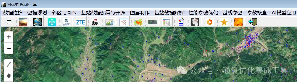
⑪ Supports geographic data visualization of base station cell KPI data (MR, traffic distribution, user distribution, PRB utilization).
⑫ Supports batch PCI reuse distance verification, supports neighboring cell distance verification across the entire network, supports MML script organization.
⑬ Online map selection for base station cell data extraction function.
⑭ 4G, 5G neighboring cell parameter verification: PLMN, PCI, TAC, frequency point, etc.
⑮ Application of AI deep learning models.
7 Operation Instructions
Login Interface
No installation required, green software, the first time using this software, directly open “Network Optimization Integration Optimization Tool.exe”. 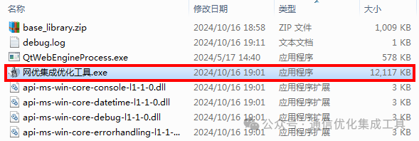
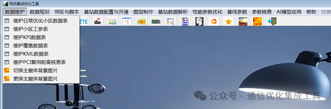
The main interface of the tool: 1: Menu bar 2: Main function display area 3: The main interface right-click: change window background image, exit the system.
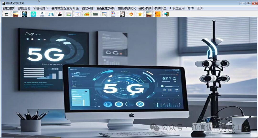
The function menu screenshot is as follows.
 DataPreparation: 4G, 5G base station cell working parameter data
A)The working parameter data sample is shown in the following figure:The cell data table, the header cannot be changed, otherwise it will cause errors. Prepare local 4G and 5G working parameter tables, the 4G and 5G working parameter headers must include the following fields: base station identification, base station name, sector number, local cell identification, cell identification, center frequency (4G is the center frequency, 5G is the SSB frequency), PCI, TAC, cell name, longitude, latitude, root sequence, bandwidth, scene, station type, azimuth, PLMN as shown in the table below.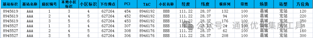
In the working parameters, the “scene” is divided into 6 categories: urban, rural, suburban, county town, suburban, town. The “station type” is divided into 4 categories: indoor distribution, macro station, micro station, high-speed rail.
B)Modify working parameter data: Click on the “Data Maintenance” menu, then click the submenu “Maintain Cell Working Parameter Table” to modify it to local data.
The format screenshot of the 4G and 5G working parameter data across the entire network is as follows: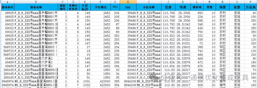
Data Preparation: 4G and 5G Base Station Cell Data
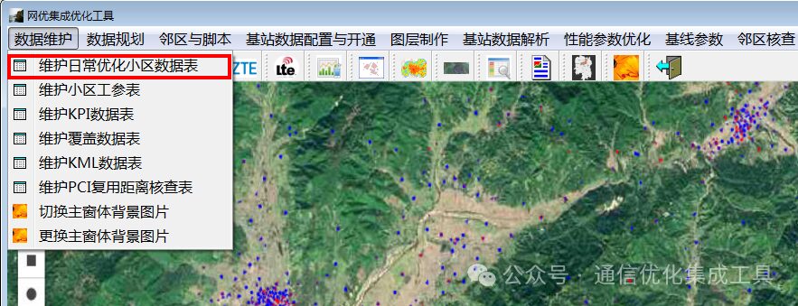
A)Sample data of the base station TOP cell table is shown in the following figure:The cell data table, the header cannot be changed, otherwise it will cause errors. Prepare local 4G and 5G base station TOP tables, the headers must include the following fields: base station name, Local Cell or CELLID, cell name, as shown in the table below. 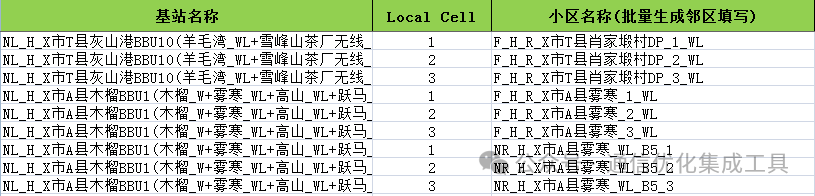 B)Modify base station cell data: Click on the “Data Maintenance” menu, then click the submenu “Maintain Daily Optimization Cell Data Table” to modify it to local data. The specific steps are shown in the following figure.
8 Generate Inter-Frequency Networking Voice and Data Layering Script Example
Click on the “Performance Parameter Optimization” menu, then click the submenu “4G Base Station Cell Optimization” to bring up the sub-window interface. As shown in the following example.
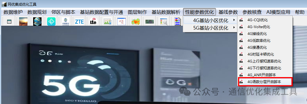
Then click the menu “4G Base Station Cell Optimization”, and the submenu “4G Voice and Data Layering Script” will bring up the sub-window interface. As shown in the following example.
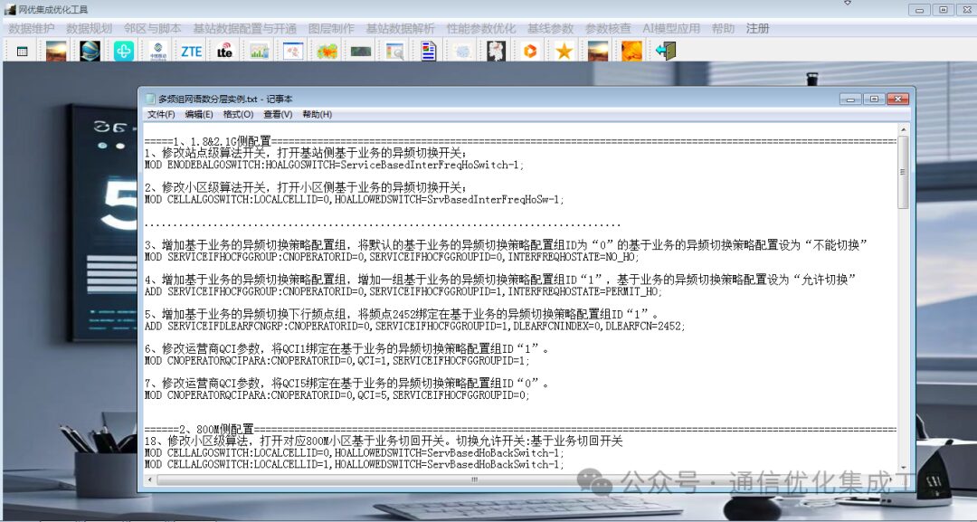
=====1. Configuration for 1.8G & 2.1G Side
1. Modify the site-level algorithm switch to enable the base station-side service-based inter-frequency handover switch;
MOD ENODEBALGOSWITCH:HOALGOSWITCH=ServiceBasedInterFreqHoSwitch-1;
2. Modify the cell-level algorithm switch to enable the cell-side service-based inter-frequency handover switch;
MOD CELLALGOSWITCH:LOCALCELLID=0,HOALLOWEDSWITCH=SrvBasedInterFreqHoSw-1;
3. Add a service-based inter-frequency handover policy configuration group, setting the default service-based inter-frequency handover policy configuration group ID “0” to “no handover”.
MOD SERVICEIFHOCFGGROUP:CNOPERATORID=0,SERVICEIFHOCFGGROUPID=0,INTERFREQHOSTATE=NO_HO;
4. Add a service-based inter-frequency handover policy configuration group, adding a service-based inter-frequency handover policy configuration group ID “1” and setting it to “allow handover”.
ADD SERVICEIFHOCFGGROUP:CNOPERATORID=0,SERVICEIFHOCFGGROUPID=1,INTERFREQHOSTATE=PERMIT_HO;
5. Add a service-based inter-frequency handover downlink frequency point group, binding frequency point 2452 to the service-based inter-frequency handover policy configuration group ID “1”.
ADD SERVICEIFDLEARFCNGRP:CNOPERATORID=0,SERVICEIFHOCFGGROUPID=1,DLEARFCNINDEX=0,DLEARFCN=2452;
6. Modify the operator QCI parameters, binding QCI1 to the service-based inter-frequency handover policy configuration group ID “1”.
MOD CNOPERATORQCIPARA:CNOPERATORID=0,QCI=1,SERVICEIFHOCFGGROUPID=1;
7. Modify the operator QCI parameters, binding QCI5 to the service-based inter-frequency handover policy configuration group ID “0”.
MOD CNOPERATORQCIPARA:CNOPERATORID=0,QCI=5,SERVICEIFHOCFGGROUPID=0;
======2. Configuration for 800M Side
18. Modify the cell-level algorithm to enable the corresponding 800M cell service-based fallback switch. Handover allowed switch: service-based fallback switch.
MOD CELLALGOSWITCH:LOCALCELLID=0,HOALLOWEDSWITCH=ServBasedHoBackSwitch-1;
MOD CELLALGOSWITCH:LOCALCELLID=1,HOALLOWEDSWITCH=ServBasedHoBackSwitch-1;
MOD CELLALGOSWITCH:LOCALCELLID=2,HOALLOWEDSWITCH=ServBasedHoBackSwitch-1;
======3. Network-wide Configuration
8. Modify cell QCI parameters, changing the handover configuration QCI priority of QCI1 to “1”.
MOD CELLQCIPARA:LOCALCELLID=0,QCI=1,QCIPRIORITYFORHO=1;
9. Modify cell QCI parameters, changing the handover configuration QCI priority of QCI5 to “2”.
MOD CELLQCIPARA:LOCALCELLID=0,QCI=5,QCIPRIORITYFORHO=2;
10. Add an inter-frequency handover parameter group, adding an inter-frequency handover parameter group “1”.
ADD INTERFREQHOGROUP:LOCALCELLID=0,INTERFREQHOGROUPID=1;
11. Modify cell QCI parameters, binding the inter-frequency handover parameter group of QCI1 to “1”. QCI algorithm switch: allow executing inter-frequency load balancing; allow handover using VoIP frequency points.
MOD CELLQCIPARA:LOCALCELLID=0,QCI=1,INTERFREQHOGROUPID=1,QciAlgoSwitch=INTER_FREQ_MLB_ALLOWED-1&HO_USE_VOIP_FREQ_ALLOWED-1;
12. Modify cell QCI parameters, binding the inter-frequency handover parameter group of QCI5 to “0”.
MOD CELLQCIPARA:LOCALCELLID=0,QCI=5,INTERFREQHOGROUPID=0,QciAlgoSwitch=INTER_FREQ_MLB_ALLOWED-1&HO_USE_VOIP_FREQ_ALLOWED-0;
13. Modify cell standard QCI parameters, binding the inter-frequency handover parameter group of QCI1 to “1”, changing the handover configuration QCI priority to “1”.
MOD CELLSTANDARDQCI:LOCALCELLID=1,QCI=QCI1,INTERFREQHOGROUPID=1,QCIPRIORITYFORHO=1,QciAlgoSwitch=INTER_FREQ_MLB_ALLOWED-1&HO_USE_VOIP_FREQ_ALLOWED-1;
14. Modify cell standard QCI parameters, binding the inter-frequency handover parameter group of QCI5 to “0”, changing the handover configuration QCI priority to “2”.

MOD CELLSTANDARDQCI:LOCALCELLID=1,QCI=QCI5,INTERFREQHOGROUPID=0,QCIPRIORITYFORHO=2,QciAlgoSwitch=INTER_FREQ_MLB_ALLOWED-1&HO_USE_VOIP_FREQ_ALLOWED-0;
15. Modify cell – enable multi-frequency measurement control. Multi-frequency priority control switch: fixed measurement object ID switch: on & VoIP measurement frequency priority switch: on & data service measurement frequency priority switch: off.
MOD CELLALGOSWITCH:LocalCellId=1,MultiFreqPriControlSwitch=FixedMeasObjIDSwitch-1&VoipMeasFreqPriSwitch-1&PsMeasFreqPriSwitch-0;
Handover signaling optimization switch: A2 measurement switch added when QCI changes: on.
16. Modify cell to enable the A2 measurement switch added when QCI changes (default on, it has been found that some sites manually turn it off, it needs to be turned on when different QCI configurations have different inter-frequency handover parameters).
MOD ENODEBALGOSWITCH:HOSIGNALINGOPTSWITCH=AddA2MeasIfQciAdjSwitch-1;
17. Modify cell MLB handover parameter configuration, turn off the cell handover admission switch. MLB and other feature coordination: handover admission switch: off.
MOD CELLMLBHO:LOCALCELLID=0,MLBMATCHOTHERFEATUREMODE=HoAdmitSwitch-0;
=====4. Handover Parameters
1. Modify the INTERFREQHOEVENTTYPE=EventA3 between 1.8 and 2.1.
MOD EUTRANINTERNFREQ:LOCALCELLID=0,DLEARFCN=100,INTERFREQHOEVENTTYPE=EventA3;
MOD EUTRANINTERNFREQ:LOCALCELLID=0,DLEARFCN=1825,INTERFREQHOEVENTTYPE=EventA3;
2. Modify the voice and data handover thresholds from 800M to 1.8 & 2.1. Data:
MOD INTERFREQHOGROUP:LOCALCELLID=0,INTERFREQHOGROUPID=0,INTERFREQHOA1THDRSRP=-75,INTERFREQHOA2THDRSRP=-80,INTERFREQHOA4THDRSRP=-105; Voice:
MOD INTERFREQHOGROUP:LOCALCELLID=0,INTERFREQHOGROUPID=1,INTERFREQHOA1THDRSRP=-102,INTERFREQHOA2THDRSRP=-107,INTERFREQHOA4THDRSRP=-92;
3. Modify the voice and data handover thresholds from 1.8 & 2.1G to 800M. Data:
MOD INTERFREQHOGROUP:LOCALCELLID=0,INTERFREQHOGROUPID=0,INTERFREQHOA1THDRSRP=-105,INTERFREQHOA2THDRSRP=-109,INTERFREQHOA4THDRSRP=-105; Voice:
MOD INTERFREQHOGROUP:LOCALCELLID=0,INTERFREQHOGROUPID=1,INTERFREQHOA1THDRSRP=-90,INTERFREQHOA2THDRSRP=-95,INTERFREQHOA4THDRSRP=-105;
4. Modify the voice and data handover thresholds from 1.8G to 2.1G. Data:
MOD INTERFREQHOGROUP:LOCALCELLID=0,INTERFREQHOGROUPID=0,INTERFREQHOA3OFFSET=6,A3INTERFREQHOA1THDRSRP=-105,A3INTERFREQHOA2THDRSRP=-109; Voice:
MOD INTERFREQHOGROUP:LOCALCELLID=0,INTERFREQHOGROUPID=1,INTERFREQHOA3OFFSET=4,A3INTERFREQHOA1THDRSRP=-95,A3INTERFREQHOA2THDRSRP=-100; Use the integration optimization tool to generate scripts, as shown in the following example:
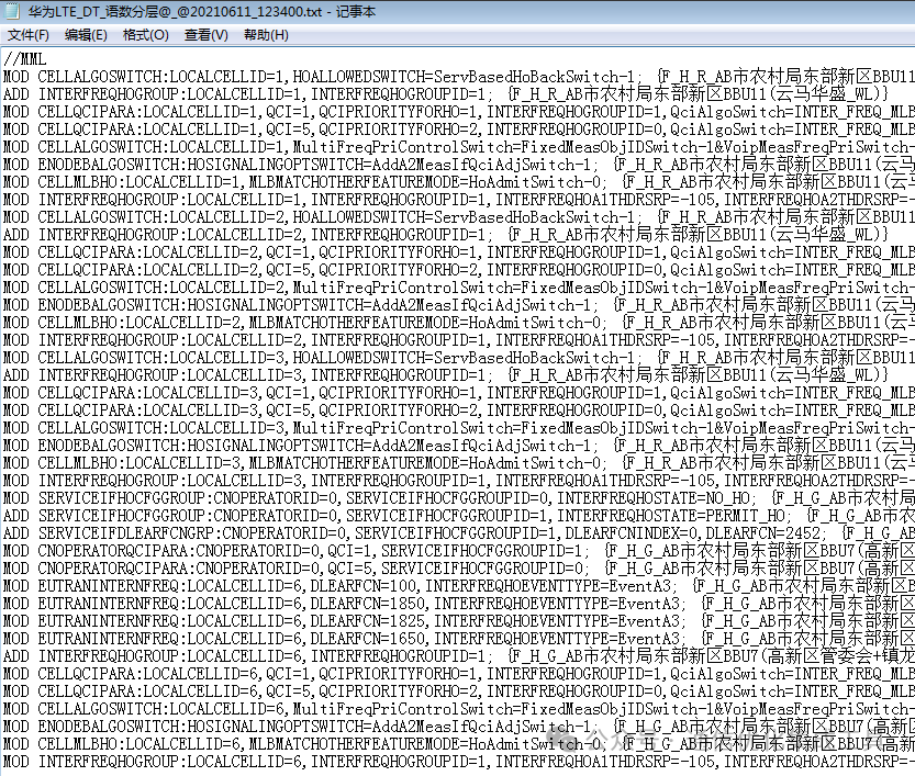
The parameter settings for inter-frequency networking voice and data layering are a complex and meticulous process. By scientifically configuring inter-frequency handover groups, base station cell function switches, QCI parameters, and multi-frequency measurement control, the advantages of each frequency band can be fully utilized, achieving efficient carrying of voice and data services, and providing users with a high-quality, stable communication service experience.
Finally, complete this function and return to the main interface, as shown in the following figure.

In today’s rapidly developing digital age, the continuous evolution of communication technology poses higher demands on network planning. The popularity of 4G/5G networks has made neighboring cell planning a key link in ensuring communication quality and user experience. The integration of WebGid, AI, and big data processing technology has brought innovative changes and powerful empowerment to batch 4G/5G neighboring cell planning.
Big data processing technology can collect and integrate massive network data, including base station information, user behavior, signal strength, etc. Through in-depth analysis of this data, the current state of network coverage and the distribution of user needs can be accurately depicted.
WebGid, AI, and big data processing technology play their intelligent optimization capabilities based on this. By utilizing machine learning algorithms, potential neighboring cell relationships can be automatically identified, predicting signal interference and capacity bottlenecks in the network. Moreover, through continuous self-learning and adjustment, AI can continuously optimize neighboring cell planning schemes to adapt to the dynamic changes in the network.
In practical applications, the combination of AI and big data processing technology not only improves the efficiency and accuracy of neighboring cell planning but also significantly reduces the cost and error rate of manual intervention. It can quickly generate optimal neighboring cell planning strategies, significantly enhancing the performance of 4G/5G networks and providing users with more stable and high-speed communication services.
Looking to the future, as WebGid, AI, and big data technology continue to develop and improve, their application in mobile communication 4G/5G networks will become deeper and more extensive, injecting continuous momentum into the development of the communication industry and creating a more intelligent and efficient network era.
Version Registration
Click on the “Register” menu, then click the submenu “Generate Registration Code”, as shown in the figure. After obtaining the registration loading code file, click the submenu “Load Registration Code” to complete the registration.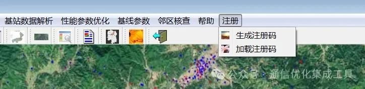
You can generate a registration code, contact maintenance personnel to apply for a License, and become a formal version. How to obtain it: Developer contact information (WeChat ID: bsyr8988), or scan the QR code to add WeChat, as shown in the figure below.