This article mainly introduces an embedded system architecture design method based on event-driven and modular layered design principles, which can effectively improve the stability of instruments and simplify subsequent maintenance work.
Event-Driven Embedded Systems Architecture Design for Intelligent Instruments
Jin Miao, Guo Yueming, Wei Qian, Tang Jie
(Beijing Zhongyou Ruifei Information Technology Co., Ltd.,
Changping, Beijing, 102200)
Abstract: This article introduces an event-driven embedded system architecture design method that adopts a modular layered design principle. The system architecture consists of a hardware abstraction layer, application support sub-layer, application layer, and event-driven core, which can be widely implemented on MSP430, M3, Arm, X86 architectures, demonstrating general applicability. This architecture fully considers the demand characteristics of intelligent instruments, effectively enhancing instrument stability and simplifying subsequent maintenance work.
Keywords: event-driven; layered design; modularity; function library
Embedded Systems Architecture Design of Intelligent Instruments Based on Event Driven
1. Introduction
With the rapid development of the Internet of Things in oil and gas production, intelligent instrument devices are widely used in the field of automation both domestically and internationally. However, due to significant differences in the development environments of instruments used in the automation industry and the many technical branches of products, the embedded code interfaces are not unified, leading to poor code reusability and increased difficulty in subsequent technical communication. At the same time, with the refinement of industry demands for instrument products and the standardization of hardware modular interfaces, it is feasible and necessary to conduct a unified embedded system architecture design for instrument products.
The event-driven embedded system architecture design method introduced in this article employs a layered design principle, achieving functional modular encapsulation to maximize system stability and interface unification. It can be easily ported to other MCU and instrument platforms, allowing users to implement necessary product function selections through simple macro definitions, abstracting the interfaces of various functional components and achieving unification, conveniently extending other functional components or adding event handling tasks.
1.1 System Architecture Functional Requirements
According to the current industry demands for intelligent instruments, they need to implement functions such as device management, human-machine interaction, and data uploading. The specific system functional components are shown in Figure 1-1.
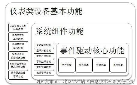
Figure 1-1 Intelligent Instrument System Functional Components Diagram
As early as 1979, a specialized committee of the International Organization for Standardization (ISO) proposed the seven-layer model of network structure based on the functional layering concept for the formulation of standards related to “Open Systems Interconnection” (OSI) – the Open Systems Interconnection Reference Model (OSI/RM). Although OSI/RM was established for interconnecting systems in networks, its layered design concept can be fully referenced for the design of intelligent instrument embedded system architecture.
As early as 1979, a specialized committee of the International Organization for Standardization (ISO) proposed the seven-layer model of network structure based on the functional layering concept for the formulation of standards related to “Open Systems Interconnection” (OSI) – the Open Systems Interconnection Reference Model (OSI/RM). Although OSI/RM was established for interconnecting systems in networks, its layered design concept can be fully referenced for the design of intelligent instrument embedded system architecture.
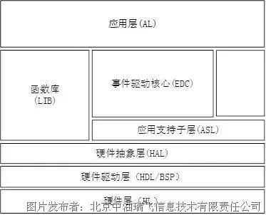
Figure 1-2 Embedded System Architecture Layer Diagram
2. Analysis and Design of the Working Principles of Each Layer of the System
According to the layered design concept of the system, each layer encapsulates the next layer, so the code execution process requires a gradual call and cannot skip layers. The specific calling process between layers is shown in Figure 2-1.
With the implementation of modularization of instrument hardware and standardization of interfaces, a foundation for modular software design has been established. Based on the functional requirements of instruments, the hardware layer is divided into basic units such as the main control module, sensor module, HMI module, and communication module.
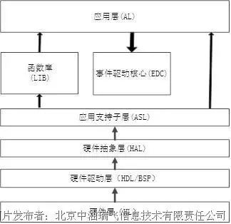
Figure 2-1 System Layer Calling Flowchart
2.1 Hardware Abstraction Layer (HAL)
2.1.1 Working Principle of the Hardware Abstraction Layer
The Hardware Abstraction Layer (HAL) completes further encapsulation of hardware module interfaces, including both internal bus devices of the MCU and external devices. The HAL, as the upper layer of the BSP and the lower layer of the application support sub-layer, is a crucial layer of the entire system architecture, encapsulating the underlying devices and providing a unified interface for the application support sub-layer and other functional modules within the system architecture. To achieve this function and code universality, each software and hardware module must be uniquely encoded to distinguish different devices, utilizing device encoding to achieve different operations for the same device through dynamic mapping of callback functions.
According to the characteristics of the instruments, operations on devices can be abstracted into several sub-operation interfaces, unifying these sub-operations into a structure to achieve unification of the upper-layer interfaces. For example, operations on conventional devices can be abstracted into six sub-operation interfaces: open, read, write, sleep, diagnose, and close. The design of the conventional device interface in the hardware abstraction layer is shown in Figure 2-2. When writing device abstraction layer code, the above six interfaces must be abstracted from the BSP layer interface for use by the application support sub-layer and other functional modules. The device operation structure design is as follows:
Struct Hal_Dev{ .DEV_CODE, .read, .write, .open, .close, .diagnostic, .sleep }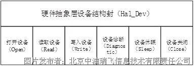
Figure 2-2 Design Diagram of Conventional Device Structure Interface in Hardware Abstraction Layer
In actual coding of the hardware abstraction layer, different operation interfaces can be mounted through the open function. For example, if the application support sub-layer needs to operate a certain sub-device in the sensor module of the hardware abstraction layer, it first passes the encoding of the sub-device (the device encoding is globally unique) to the open function, which then finds the operation interface of that device based on the unique encoding and assigns its address to the structure’s interface.
2.1.2 Interrupt Handling Interface in the Hardware Abstraction Layer
To promptly respond to user demands, the hardware abstraction layer can provide an interrupt handling mechanism for infrared interfaces and communication module interfaces, involving modules such as the infrared communication module, local communication module, and remote communication module. In this system architecture design, there are only two types of interrupts: timer interrupts and UART data reception interrupts. Timer interrupts are used to drive event operations, while UART interrupts are used to transport data from the UART buffer to the data area when they occur. The event flowcharts for RTC interrupt triggers and UART interrupt triggers are shown in Figures 2-3 and 2-4, respectively.
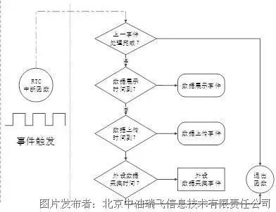
Figure 2-3 Event Flowchart When RTC Interrupt is Triggered
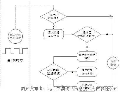
Figure 2-4 Event Flowchart When UART Interrupt is Triggered
2.2 Application Support Sub-Layer
The application support sub-layer is the second hub of the entire system, providing the connection between the hardware abstraction layer and the application layer as well as the instrument function library. In terms of hierarchical functions, this layer further encapsulates the hardware abstraction for easier invocation when the application layer encapsulates event operation interfaces. It mainly consists of interfaces related to sensor operations, data access, data display, and data transmission. Compared to the interfaces provided by the instrument function library, this layer’s interfaces focus more on encapsulating hardware interfaces and act as a bridge establishing connections between other functional components of the system and the event-driven core, providing more user-friendly device interfaces for the application layer and the event-driven core.
Taking the sensor module interface as an example, during the operation of the entire system, sensor operations are the most frequent task, and the entire system is basically centered around the sensor. Based on the modular design scheme, it can be determined that sensor operations involve three aspects: real-time data reading, sensor information reading, and sensor diagnostics. For the MCU, this essentially involves some read and write operations on the SPI interface, which have already been implemented in the HAL. Here, an interface needs to be designed to encapsulate operations such as real-time data reading, sensor information reading, and condition diagnostics, as shown in Figure 2-5.
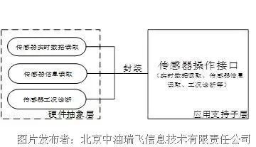
Figure 2-5 Sensor Module Application Support Sub-Layer Interface
2.3 Instrument Function Library
The instrument function library encapsulates software modules for instrument products, mainly including communication protocol modules, file systems, device management modules, algorithm modules, intelligent power management modules, and also includes standard functions from the C language. This system architecture supports input/output functions and mathematical functions from the standard C function library.
Through the construction of the code library, code specifications can be unified, commonly used function interfaces can be standardized, and reusability can be avoided, thereby improving the efficiency of embedded software engineers.
2.4 Application Layer
Different devices have different application scenarios, and the same device may have different application requirements. How can the system architecture be unified to concentrate programmers’ workloads on solving practical problems rather than on the entire system? This relies on the design of the application layer, which will instantiate operation interfaces for human-machine interaction events, remote device management events, data uploading events, data display events, real-time data collection events, external device data collection events, and historical data access events. The event-driven center will execute the above event handling functions, and the relationship between the application layer and each layer is shown in Figure 2-7. For example, in the case of the sensor data upload event, this event operates mainly in two aspects: passive uploading, which is initiated when the upper computer has a demand, mainly applied in the bus architecture of the master-slave structure; and active uploading, which depends on specific communication protocols like the A11 communication protocol. At the same time, this event completes data packaging and sending, calling the communication protocol interface and the communication module data sending interface.
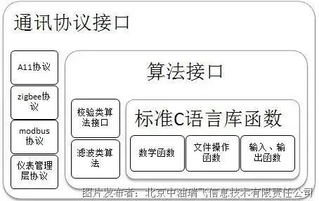
Figure 2-7 Relationship Diagram Between Application Layer and Each Layer
2.5 Event-Driven Core
The main function of the event-driven core is to arbitrate the sequence of tasks in the system. The “heartbeat” of the event-driven core is completed in the hardware abstraction layer, determining or triggering events through the RTC clock tick. The purpose of designing this part is to allow application layer engineers to focus on user demands, as in most cases, the design of the event-driven core and its related sub-layers is the core task of the entire system. Regular maintenance and updates of this “kernel” can upgrade the product. The relationship between the event-driven core and each layer is shown in Figure 2-8.
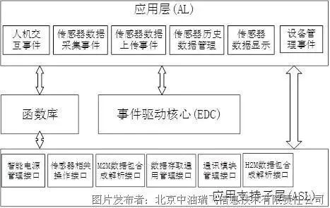
Figure 2-8 Relationship Diagram Between Event-Driven Core and Each Layer
Based on the event-driven interface, a structure Event can be encapsulated, which contains information about the current and previous events, and can also transmit data pointers between events, as follows:
Struct Event{CurrentEvent,.PreEvent,Pdata}3. Conclusion
The layered design and gradual calling code architecture design method introduced in this article has been used in the next generation of intelligent instruments and has achieved significant results. In the software code design of intelligent instruments, utilizing this layered system architecture design has the following advantages:
(1) Improved software quality and shortened product development cycles. During the instrument development period, unified function interfaces and centralized management of commonly used algorithms greatly enhance code reusability, avoid redundant development, thereby further improving developer utilization, reducing the workload of embedded code engineers, and shortening product development time.
(2) Simplified later upgrades and maintenance of devices. During the instrument maintenance period, a clear program structure and unified interfaces can effectively avoid latent bugs and improve product stability; when changing the specific implementation code of layers, as long as the function interfaces remain stable, there is no need to modify other functions, greatly simplifying product upgrade and maintenance work.
References:
[1] Jia Ling, Wang Xinyu, Zheng Shujun, et al. Principles and Practices of IoT/Wireless Sensor Networks [M]. Beijing University of Aeronautics and Astronautics Press, 2011, 1.
[2] Meng Yanjing, Chen Zhuo, Application of Event-Driven Programming Method in Embedded Systems [J]. Electrical Automation, 2009, Issue 06.
[3] Li Chenliang, Event-Driven Architecture and Applications [J]. Software World, 2007, Issue 21.
[4] He Hongjun, Cao Sihua, Chu Zugao, Luo Li, Ning Jingyi, Dong Liming, Li Peng, An Improved Event-Driven System Framework [J]. Journal of National Defense Science and Technology University, 2008, Issue 03.
[5] Sun Qiudong, Layered Design of Software Systems [J]. Computer Engineering and Applications, 2001, Issue 07.
Source: China Industrial Control Network
Authors | Jin Miao, Guo Yueming, Wei Qian, Tang Jie
Compiled by | Embedded Application Research Institute
Author Profile: Jin Miao, female, April 1986, Beijing Zhongyou Ruifei Information Technology Co., Ltd., Master, Embedded Software Engineer, main research direction is the application of embedded systems and IoT technology in oil and gas production. Email: [email protected], Phone: 13311200610.
Guo Yueming, male, Beijing Zhongyou Ruifei Information Technology Co., Ltd.
Wei Qian, male, Beijing Zhongyou Ruifei Information Technology Co., Ltd.
Tang Jie, male, Beijing Zhongyou Ruifei Information Technology Co., Ltd.
Reprinted from | Arm Technology Academy
Copyright belongs to the original author, if there is any infringement, please contact to delete.
END