112023 Good News
© dream18560710



INVITATION
Embedded Systems
Design Teaching

Design of Embedded Intelligent Car Based on RTT-Thread (2)

Intelligent Car Practical Education Base
Design of Embedded Intelligent Car Based on RTT-Thread
Instructor:Gou Jun Nian



Practical Design Instructions

As part of the process assessment for the “Embedded System Design” course, the hands-on practical section involves designing and implementing an intelligent car based on RT-Thread, with the following specific requirements:
1. This section is a mandatory part of the process assessment, accounting for 20% of the total score;
2. This section is to be completed in groups (grouping organized by the instructor), with scores assessed by group;
3. The physical production of the car and a scenario-based operational demonstration are required;
4. Groups will complete design, integration, debugging, analysis, and summary report defense (reporting in video format, with a duration of no less than 15 minutes);
5. Specific requirements will be adjusted and explained by the relevant instructors.

1.2 Practical Operation Steps
As part of the process assessment for the “Embedded System Design” course, the hands-on practical section involves designing and implementing an intelligent car based on RT-Thread, with the following specific requirements:
1. This section is a mandatory part of the process assessment, accounting for 20% of the total score;
2. This section is to be completed in groups (grouping organized by the instructor), with scores assessed by group;
3. The physical production of the car and a scenario-based operational demonstration are required;
4. Groups will complete design, integration, debugging, analysis, and summary report defense (reporting in video format, with a duration of no less than 15 minutes);
5. Specific requirements will be adjusted and explained by the relevant instructors.

Design Scheme and Principles

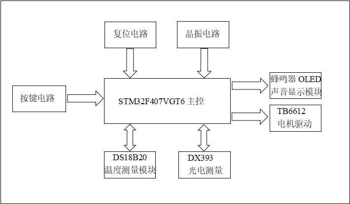
This scheme uses the STM32F407VGT6 microcontroller as the control core, builds an embedded intelligent car using RTT-thread as the operating system, employs the DS18B20 smart temperature sensor as the temperature measurement component to detect environmental temperature, uses an ultrasonic module for distance measurement, employs the XD393 module as a line-following sensor, and uses a buzzer LED light module as a message indicator.
The overall design scheme diagram is shown in Figure 1:

Hardware Design


3.1 Hardware Selection
(1) Microcontroller: The STM32F407VGT6 microcontroller chip is used, featuring a 32-bit ARM Cortex-M4 processor core, with single-cycle MAC instructions, built-in flash memory of up to 1MB and 192KB of SRAM. It supports various communication interfaces such as USB OTG FS, CAN, I2C, SPI, USART, etc., allowing easy connection to various peripheral devices. Additionally, this microcontroller provides rich analog and digital peripheral functions, such as ADC, DAC, timers, PWM, and GPIO, providing strong support for implementing complex functions.
(2) Motor Driver Module: The TB6612FNG is a DC motor driver device produced by Toshiba Semiconductor, featuring a high-current MOSFET-H bridge structure, dual-channel circuit output, capable of driving 2 motors simultaneously. It has a high level of integration while providing sufficient output capability, with advantages in operational performance and energy consumption, making it an ideal motor driver device for integrated and miniaturized motor control systems.
(3) Display Module: OLED, or Organic Light Emitting Diode. OLEDs are considered the next generation of flat display technology due to their self-emitting nature, high contrast, thin profile, wide viewing angles, fast response times, suitability for flexible panels, wide operating temperature range, and relatively simple construction and processing.
(4) Temperature Measurement Module: The DS18B20 one-wire digital temperature sensor is used, with a measurement range of -55℃ to 125℃, programmable A/D conversion precision from 9 to 12 bits, and a measurement resolution of 0.0625℃. The CPU only requires one pin to communicate with the DS18B20, minimizing pin usage and saving a significant amount of wiring and logic circuitry.
(5) Line Following Module: The XD393 photoelectric sensor module. Each XD393 provides two sets of comparators, with 1IN+, 1IN-, and 1OUT as one set, and 2IN+, 2IN-, and 2OUT as another set. Vcc connects to the power supply, and GND connects to ground. When the potential of 1IN+ is higher than that of 1IN-, 1OUT outputs a high level; otherwise, it outputs a low level. When the potential of 2IN+ is higher than that of 2IN-, 2OUT outputs a high level; otherwise, it outputs a low level. The levels of 1OUT and 2OUT can only take two values: high level (VCC) or low level (0V, GND).
(6) Others: A matrix keypad composed of 16 independent keys is used to expand functional debugging.

3.2 PWM Driving Experiment
(1) Experiment Objectives
a. Master the method of controlling the wheel rotation speed of the car through serial terminal commands, and gain a deeper understanding of the application of PWM (Pulse Width Modulation) technology in speed control.
b. Learn to implement forward and reverse control of the car using PWM driving, further familiarizing oneself with the principles and operations of PWM technology in motor direction control.
(2) Experiment Principles
PWM technology controls the average voltage across the motor by adjusting the duty cycle of the pulse signal, thereby controlling the motor speed. In forward and reverse control, by changing the output logic of the PWM signal in conjunction with a specific motor driver circuit, the direction of the motor can be altered. PWM (Pulse Width Modulation) is a technique that controls analog signals by modulating the width of pulse signals. Its core parameters include:
Period (T): The time length of a complete pulse sequence
Frequency (f): f=1/T, determines the rate of change of the pulse signal
Duty Cycle (D): The ratio of high-level time to the period, D=tH/T×100%
By adjusting the duty cycle, the average voltage across the load can be controlled, thereby controlling the motor speed, LED brightness, etc.
This experiment’s PWM driving uses the STM32F407VGT6 hardware timer output channel. The STM32F407VGT6 is a high-performance microcontroller based on the ARM Cortex-M4 core, widely used in industrial control, IoT, smart home, and other fields, becoming a popular choice for embedded development due to its excellent performance and rich features.
(3) Experiment Environment
Hardware Environment: Development board based on STM32F407VGTx microcontroller, motor driver module, car body. Software Environment: RT-Thread Studio development environment, STM32CubeMX configuration tool.
(4) Experiment Steps
PWM driving basic configuration and speed adjustment experiment
1. BSP regular configuration
(1) Open RTT to create a new project, double-click on CubeMX Settings in the project resource explorer to open STM32CubeMX.
(2) Configure hardware in STM32CubeMX: enable external high-speed crystal oscillator; configure the debug interface to Serial Wire; enable USART1, set to asynchronous mode; configure the clock tree.
(3) After completing the configuration, save, click the generate code button, and close the relevant prompt windows and all STM32CubeMX windows.
2. PWM regular configuration
(1) Double-click on CubeMX Settings in the RTT project resource explorer again to open STM32CubeMX.
(2) Configure the hardware timer 4 (PWM4 corresponds to TIM4) of the STM32 chip, setting channels 3 and 4 to PWM output mode.
(3) Save the configuration and generate code, then close the relevant windows.
3. Enable device drivers in RT-Thread Settings
(1) Double-click RT-Thread Settings to open RT-Thread Setting, and click the relevant buttons.
(2) In the components page, ensure that the options “Use UART device driver”, “Use PIN device driver”, and “Use PWM device driver” are enabled, then save and close the page.
(3) Open the board.h file in the drivers folder, and define the PWM device-related macros in the PWM CONFIG area.
PWM driving forward and reverse control experiment
1. Create a new project that meets the requirements of the PWM driving forward and reverse control experiment, and import it into RRT.
2. Copy the main.c, motor.c, and motor.h files from the courseware folder directory to the applications directory of the project.
3. Compile and download.
4. Start the car and observe whether it operates according to the design requirements in main.c.
(5) Advantages
The STM32F407VGT6, equipped with a Cortex-M4 core, operates at a frequency of up to 168MHz and includes an FPU (Floating Point Unit) and DSP instruction set. It shows significant advantages in processing complex algorithms and large data computations, such as quickly executing PID control algorithms for high-precision motor speed and position control in industrial automation; in image processing applications, it can efficiently handle tasks like image filtering and edge detection, enhancing system response speed.

Software Design


4.1 Debugging Results
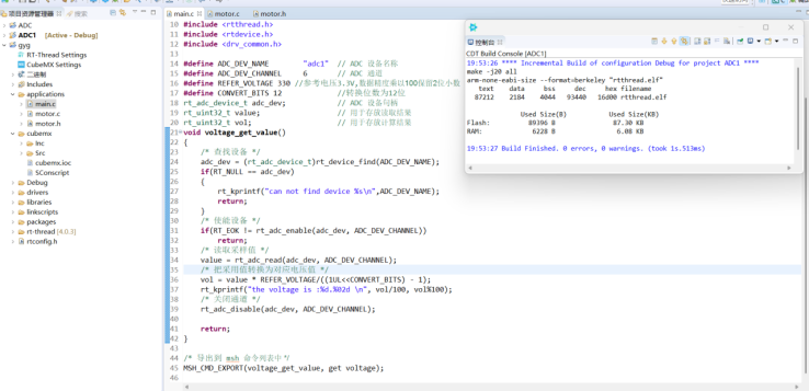
Programs were written and debugged using the RT-Thread Studio development environment. The debugging results are shown in Figure 2.

4.2 Main Program
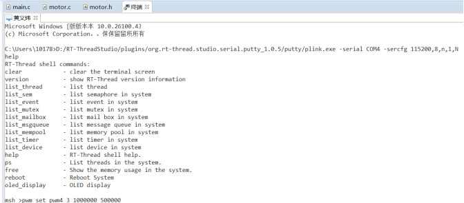
The function of the main program is to start the main program and directly enter the speed adjustment and forward/reverse control main page.The control page is shown in Figure 3.

Actual Debugging and PCB Circuit Diagram


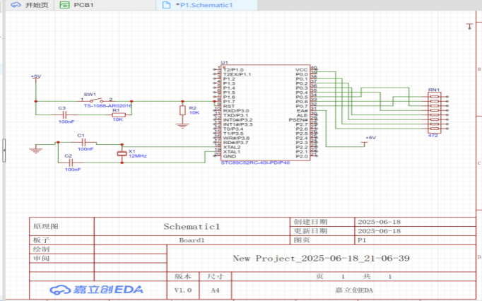
5.1 PCB Circuit Diagram

5.2 Actual Debugging Results

Summary

Through this design of the embedded intelligent car based on RTT-thread, I gained valuable learning experiences. Here are some key takeaways:
Knowledge Application and Enhancement: This design of the embedded intelligent car based on RTT-thread allowed me to deepen my understanding and consolidate my theoretical knowledge of embedded systems, and by solving practical problems, I enhanced my ability to apply theory to practice. My logical thinking skills improved significantly during the program modification and debugging process.
Understanding Hardware Design: Hardware design must meet functionality and operability. I learned to choose simple, highly integrated, and reliable hardware solutions while ensuring feasibility, and to consider how software complements hardware functions for better design.
Software Design Methods: Faced with complex software functionality, I learned to break problems down into modular smaller issues and solve them one by one, greatly improving the efficiency and clarity of problem-solving.
Defense and Report Writing: The group defense honed my logical expression skills, laying a foundation for future graduation project defenses. Additionally, through communication with teachers and classmates, I gained valuable knowledge and advice. Writing reports familiarized me with academic formatting and cultivated a rigorous work attitude.
Team Collaboration: This design of the embedded intelligent car based on RTT-thread was completed in groups, and teamwork enhanced work efficiency and improved communication and collaboration among team members. It also made me understand the benefits of teamwork.
This design of the embedded intelligent car based on RTT-thread successfully completed the tasks of controlling the wheel speed and forward/reverse control. Through the experiment, I gained a deep understanding of the principles and applications of PWM technology in motor control, and I became proficient in the development process and related configuration methods based on RT-Thread and STM32CubeMX. During the experiment, I encountered issues such as compilation errors with some devices, which were resolved by replacing alternative driver files, enhancing my problem diagnosis and resolution skills. The experimental results indicate that the experimental scheme and operational steps are correct and feasible, accumulating valuable experience for further learning and application of embedded system development. In summary, this design of the embedded intelligent car based on RTT-thread not only improved my professional skills but also trained my logical thinking and expression abilities, greatly benefiting my future academic and career development.