Reading Notes: The Definitive Guide to Cortex-M3
Note: The content of this article is excerpted from the “Definitive Guide to Cortex-M3”. The Cortex-M series is essential in embedded development, and this series will record the key points of knowledge focused on while reading the book. It is recommended to read the original book.
Chapter 7: Exceptions
7.1 Types of Exceptions
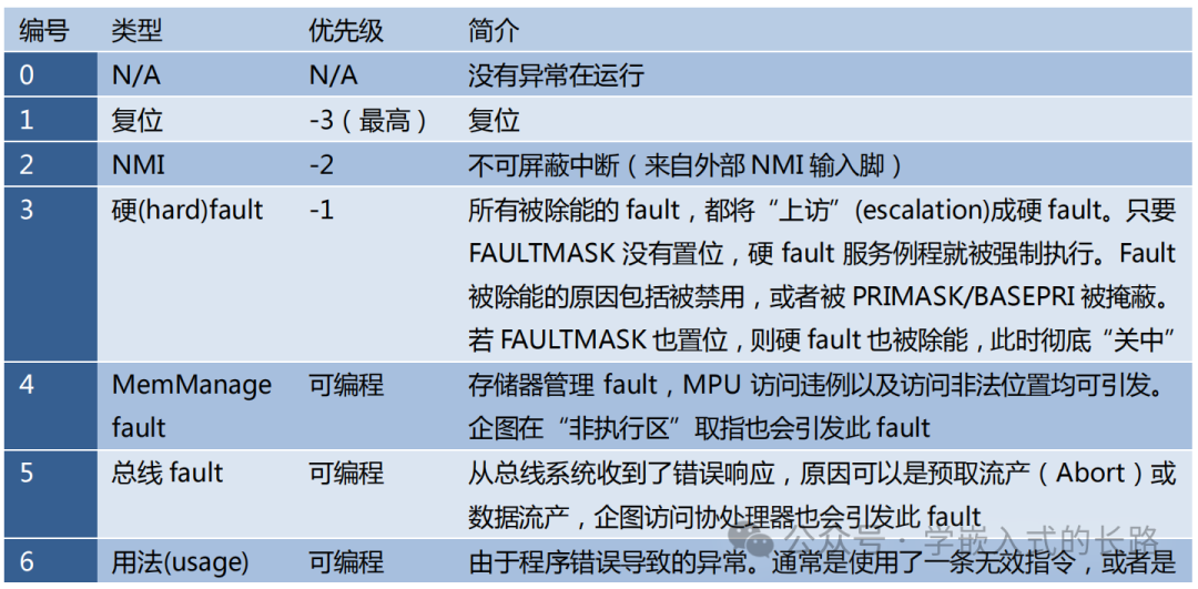
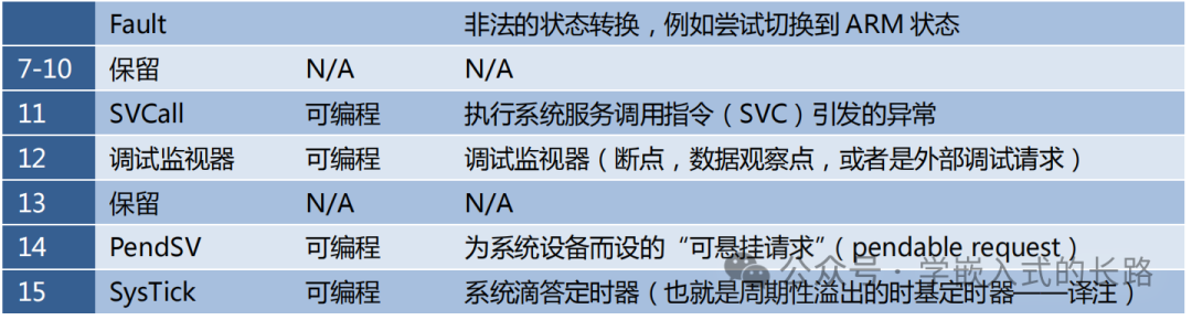
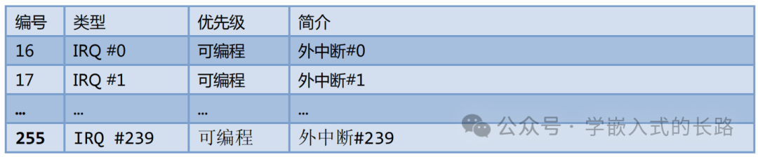
The Cortex-M3 features an exception response system at the core level, supporting numerous system exceptions and external interrupts. Among these, numbers 1-15 correspond to system exceptions, while numbers greater than or equal to 16 are external interrupts. Except for a few exceptions with fixed priorities, the priorities of other exceptions are programmable.
- • List of System Exceptions
- • List of External Interrupts
If an occurring exception cannot be immediately responded to, it is said to be “pending”. However, a few fault exceptions are not allowed to be pending. An exception may be pending because the system is currently executing a higher priority exception’s service routine, or due to the settings of related mask bits that disable the exception. For each exception source, there is a corresponding “pending status register” that saves its exception request when it is pending. When the exception can be responded to, its service routine is executed, which is completely different from traditional ARM. In the past, the device generating the interrupt held the request signal; CM3 resolves this issue with the NVIC’s pending status register. Thus, even if the device later releases the request signal, the previous interrupt request will not be missed.
7.2 Definition of Priority
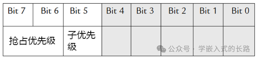
In CM3, priority is crucial for exceptions as it determines whether an exception can be masked and when it can be responded to if not masked.The smaller the priority value, the higher the priority. CM3 supports interrupt nesting, allowing high-priority exceptions to preempt low-priority exceptions. There are 3 system exceptions: Reset, NMI, and Hard Fault, which have fixed priorities, and their priority numbers are negative, thus higher than all other exceptions. All other exceptions have programmable priorities. In principle, CM3 supports 3 fixed high priorities and up to 256 levels of programmable priorities, and supports 128 levels of preemption. However, most CM3 chips are designed to be simplified, resulting in fewer supported priority levels, such as 8, 16, or 32 levels. They will cut off several low-end effective bits that express priority to reduce the number of priority levels. If only 3 bits are used to represent priority, the structure of the priority configuration register will be as shown in the following figure:
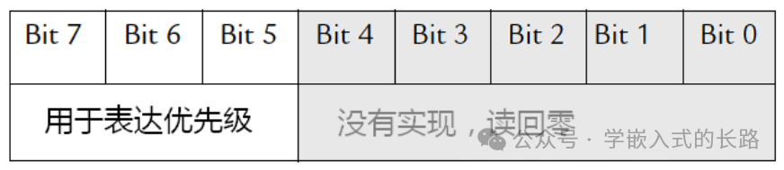
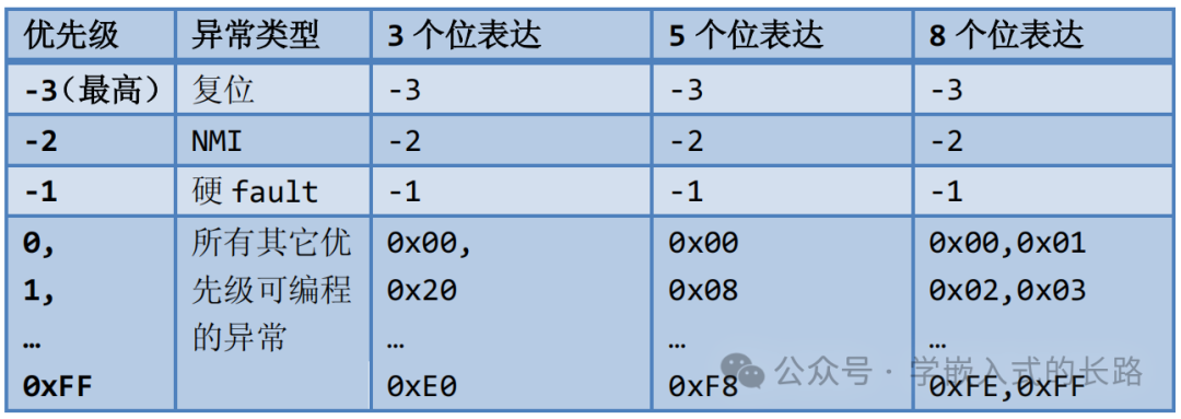
In the figure, [4:0] is not implemented, so reading them always returns zero, and writing them ignores the written value. Therefore, for the case of 3 bits, the 8 usable priorities are: 0x00 (highest), 0x20, 0x40, 0x60, 0x80, 0xA0, 0xC0, and 0xE0. If more bits are used to express priority, more values can be used, but more gates are required—leading to higher costs and power consumption. The minimum number of bits allowed by CM3 is 3, meaning it must support at least 8 priority levels. By aligning the priority to MSB, program portability across devices can be simplified. For example, if a program previously ran on a device supporting 4-bit priority, when ported to a device supporting only 3-bit priority, its functionality remains unaffected. However, if aligned to LSB, the MSB would be lost, causing values greater than 7 to suddenly increase in priority, potentially leading to “priority inversion”: making it higher than priorities less than or equal to 7. For instance, priority 8, having lost its MSB, now becomes 0; while priority 15 becomes priority 7, which does not affect priorities 0-6, making this issue more subtle. The usage of priority registers when using 3, 5, and 8 bits to express priority is shown in the following figure:
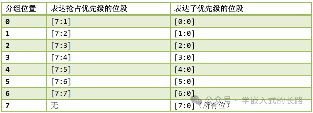
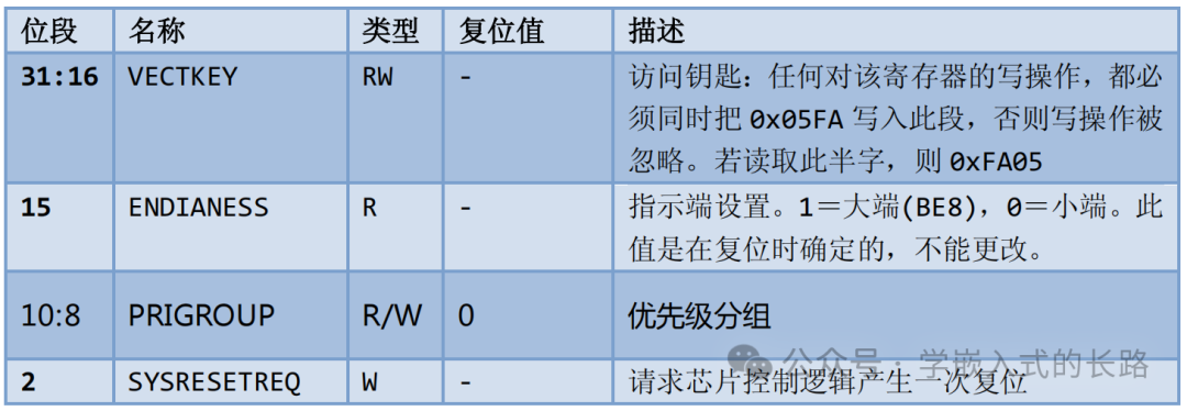
Preemptive Priority and Sub-Priority CM3 supports 256 priority levels, so why are there only 128 preemptive levels? The remaining half is due to the fact that to make preemption more controllable, CM3 divides the 256 priority levels into high and low segments, referred to as preemptive priority and sub-priority. There is a register in NVIC called the “Application Interrupt and Reset Control Register”, which contains a bit field named “Priority Group”. The value of this bit field affects every exception with configurable priority—dividing its priority into 2 segments: the segment where the MSB is located (left side) corresponds to preemptive priority, while the segment where the LSB is located (right side) corresponds to sub-priority.
Application Interrupt and Reset Control Register (AIRCR)

Preemptive priority determines the preemption behavior: When the system is responding to a certain exception L, if a higher preemptive priority exception H arrives, H can preempt L. Sub-priority handles “internal affairs”: when there are multiple pending exceptions with the same preemptive priority, the one with the highest sub-priority is responded to first. Of course, there are also three bosses that override all rules: Reset, NMI, and Hard Fault. They unconditionally preempt all priority programmable “civilian exceptions” whenever they occur. When calculating the effective bit count for preemptive priority and sub-priority, the following values must be determined:
- • How many bits the chip actually uses to express priority
- • How the priority groups are divided.
7.3 Vector Table
When an exception occurs and needs to be responded to, CM3 needs to locate the entry address of its service routine. These entry addresses are stored in the so-called “(exception) vector table”. By default, CM3 assumes this table is located at address zero, with each vector occupying 4 bytes. Therefore, each table entry occupies 4 bytes, and the vector table after power-up is shown in the following figure:
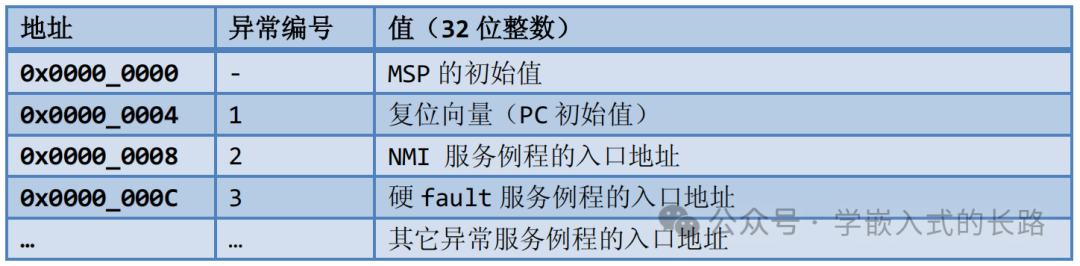
Since address 0 should store the boot code, it is usually mapped to Flash or ROM devices, and their values must not change at runtime. However, to support dynamic relocation of interrupts, CM3 allows the vector table to be relocated—starting to locate each exception vector from other addresses. These addresses can correspond to the code area, but more often are in the RAM area. In the RAM area, the entry addresses of the vectors can be modified. To implement this functionality, there is a register in NVIC called the “Vector Table Offset Register” (located at address 0xE000_ED08), and by modifying its value, the vector table can be relocated. However, it must be noted that the starting address of the vector table has requirements: the total number of vectors in the system must be determined first, then this number must be rounded up to the nearest power of 2, and the starting address must be aligned to the boundary of the latter. For example, if there are 32 interrupts, then there are 32+16 (system exceptions) = 48 vectors, rounded up to the nearest power of 2 gives 64, thus the address for vector table relocation must be divisible by 64*4=256, making the valid starting addresses: 0x0, 0x100, 0x200, etc. If the vector table needs to be changed dynamically, the start of the vector table for any device must contain the following vectors:
- • Initial value of the Main Stack Pointer (MSP)
- • Reset vector
- • NMI
- • Hard Fault service routine
7.5 Fault Class Exceptions
There are several system exceptions dedicated to fault handling. Faults in CM3 can be categorized as follows:
- • Bus faults
- • Memory management faults
- • Usage faults
- • Hard faults
7.6 SVC and PendSV
SVC (Supervisor Call, also known as system call) and PendSV (Pendable Supervisor Call) are often used in software development for operating systems. SVC is used to generate requests for system function calls. For example, operating systems typically do not allow user programs to directly access hardware, but instead provide some system service functions, allowing user programs to use SVC to issue calls to these system service functions to indirectly access hardware. Therefore, when a user program wants to control specific hardware, it generates an SVC exception, and the SVC exception service routine provided by the operating system is executed, which then calls the relevant operating system function to fulfill the user program’s request.
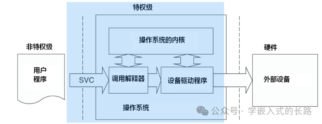
SVC exceptions are generated by executing the “SVC” instruction. This instruction requires an immediate value, which acts as the system call code. The SVC exception service routine will later extract this code to understand the specific requirements of the call and then invoke the corresponding service function. After the SVC service routine is executed, the address of the last executed SVC instruction can be calculated based on the automatically stacked return address. Once the SVC instruction is found, its machine code can be read, and the immediate value can be extracted from the machine code to know the function code being requested for execution. If the user program uses the PSP, the service routine also needs to execute the MRS Rn, PSP instruction to obtain the application program’s stack pointer. By analyzing the value of LR, it can be determined which stack was being used when the SVC instruction was executed. Another related exception is PendSV (Pendable Supervisor Call), which works in conjunction with SVC. On one hand, SVC exceptions must be responded to immediately after executing the SVC instruction (for SVC exceptions, if it cannot be immediately responded to due to priority not being higher than the currently handled one, or for other reasons, it will result in a hard fault—translator’s note), user programs executing SVC expect their requests to be responded to immediately. On the other hand, PendSV can be pending like a normal interrupt (unlike SVC which will lead to a hard fault). The OS can use it to “defer execution” of an exception—until other important tasks are completed. The method to pend PendSV is to manually write 1 to the NVIC’s PendSV pending register. Once pending, if the priority is not high enough, it will wait for execution. A typical use case for PendSV is during context switching (switching between different tasks). For example, in a system with two ready tasks, context switching can be triggered in the following scenarios:
- • Executing a system call
- • System tick timer (SYSTICK) interrupt (needed for round-robin scheduling)
Assuming there is such a system with two ready tasks, and context switching is triggered by the SysTick exception. The following figure illustrates:
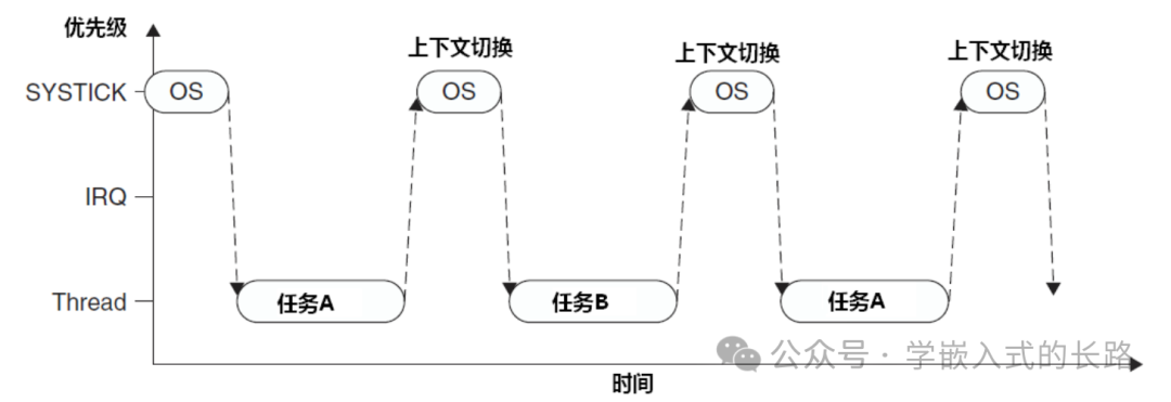
The above figure is a schematic diagram of round-robin scheduling for two tasks. However, if an interrupt is being handled when the SysTick exception occurs, the SysTick exception will preempt its ISR. In this case, the OS cannot perform context switching, as it would delay the interrupt request, and in real systems, the delay time is often unpredictable—any system with real-time requirements cannot tolerate this. Therefore, in CM3, it is strictly prohibited—if the OS attempts to enter thread mode while a certain interrupt is active, it will trigger a usage fault exception.
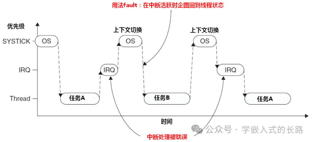
To solve this problem, early operating systems mostly checked whether there were any active interrupts, and only performed context switching when no interrupts needed to be responded to (interrupts could not be responded to during the switching). However, the drawback of this method is that it can delay task switching for a long time (because if an IRQ is preempted, the current SysTick cannot perform context switching and must wait for the next SysTick exception), especially when the frequency of a certain interrupt source is close to that of the SysTick exception, which can cause “resonance” and delay context switching.
Now PendSV can perfectly solve this problem. The PendSV exception will automatically delay the request for context switching until all other ISRs have completed processing. To implement this mechanism, PendSV must be programmed as the lowest priority exception. If the OS detects that a certain IRQ is active and is preempted by SysTick, it will pend a PendSV exception to defer context switching. The following figure illustrates:
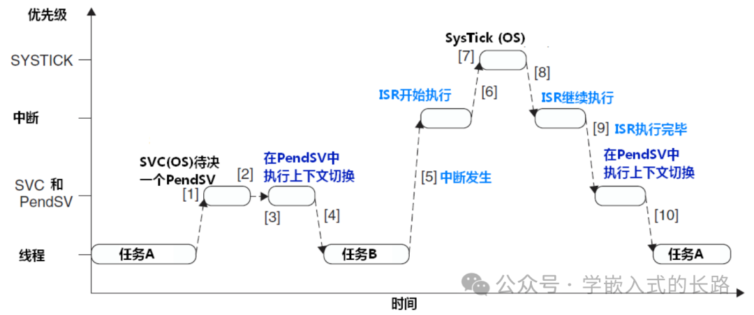
- 1. Task A calls SVC to request a task switch (for example, waiting for certain work to complete)
- 2. The OS receives the request, prepares for context switching, and pends a PendSV exception.
- 3. When the CPU exits SVC, it immediately enters PendSV to perform context switching.
- 4. After PendSV completes, it returns to Task B, while the system enters thread mode again.
- 5. An interrupt occurs, and the interrupt service routine begins execution.
- 6. During the execution of the ISR, a SysTick exception occurs and preempts the ISR.
- 7. The OS performs necessary operations and then pends the PendSV exception to prepare for context switching.
- 8. After SysTick exits, it returns to the previously preempted ISR, and the ISR continues execution.
- 9. After the ISR completes and exits, the PendSV service routine begins execution and performs context switching.
- 10. After PendSV completes, it returns to Task A, and the system enters thread mode again.