01
Identifying the ProblemI have a STM32F407G-DISC1 development board, with the MCU being STM32F407VGT6. Recently, I needed to use this board for a test, but it turned out to be non-functional. After sitting idle for a long time, it was prone to failure.I conducted some troubleshooting, first checking that there were no short circuits between the key power nodes and ground. Upon powering it up, the corresponding power nodes were also okay, with no overheating.I tested key signals like RST and found no issues, but when testing VCAP1 and VCAP2, both were at 0. The capacitors at these points are used for the chip’s internal LDO, which should provide a core voltage of around 1.8V. A reading of 0 indicates that the LDO is not functioning, leading me to suspect that the chip is dead.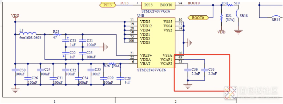 This board is from STM, and it is not cheap. It is also hard to find a replacement. Losing it and buying a new one would be a waste of resources and time.So, I decided to repair it by replacing the MCU, turning waste into treasure, which is in line with our frugal (qiong) style.As an embedded development engineer, being able to code, solder, repair, and even patch is a basic skill.
02
Preparing MaterialsI first went to a certain online marketplace to look for an MCU and found many options for just over 10 yuan, and with a coupon, it came to less than 10 yuan with free shipping. For someone like me who is frugal, this is truly heartwarming, especially after being ravaged by prices in the past two years, where the F4 series was at least 50 yuan. Unfortunately, I was too happy too soon, as I later realized that this price wouldn’t turn a bicycle into a motorcycle.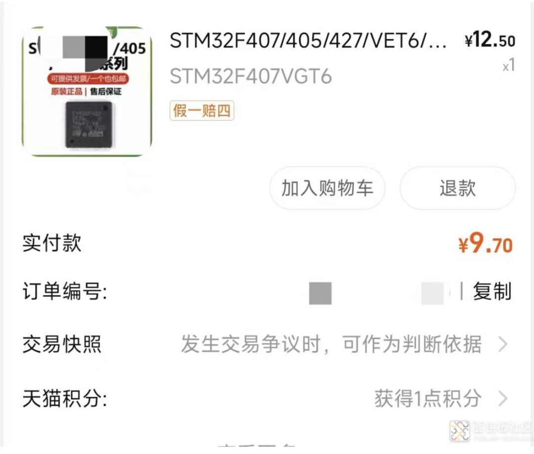 As an embedded development engineer, essential tools include a soldering iron, hot air gun, solder sucker, tweezers, and alcohol. I have everything ready, just waiting for the chip to arrive.
03
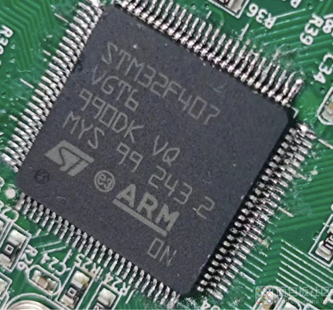
Chip ReplacementThe chip arrived, and the packaging looked good.
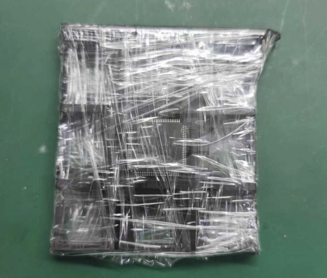
I quickly opened it up, only to find that there was still solder on the pins, indicating that it was undoubtedly a refurbished item, despite the seller labeling it as brand new. As expected, low prices come with low quality.However, as a person with a sense of justice, I thought I would just have a light-hearted chat with the seller, not expecting much. But the seller was quite defensive, and the conversation turned out to be quite interesting. I’ll share it here to pass the time. In the end, the seller was evasive, and their attitude wasn’t too bad, so I let it go. After all, we all understand the price point, but honesty is still important; if you sell refurbished items, just label them as such.
Back to the main task, let’s proceed with the replacement.
04
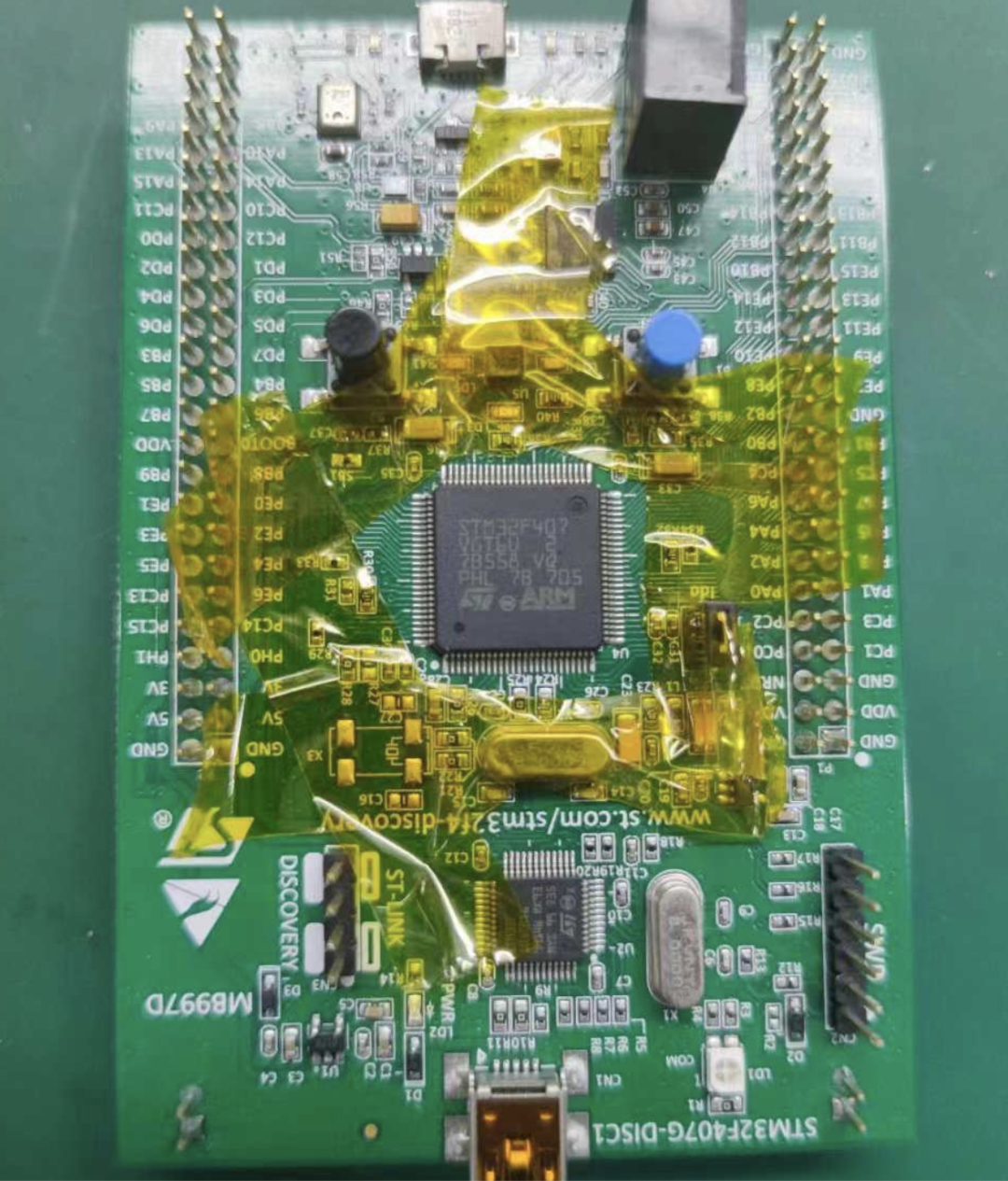
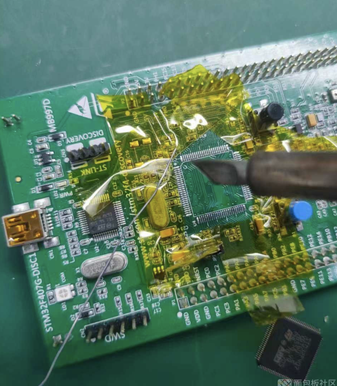
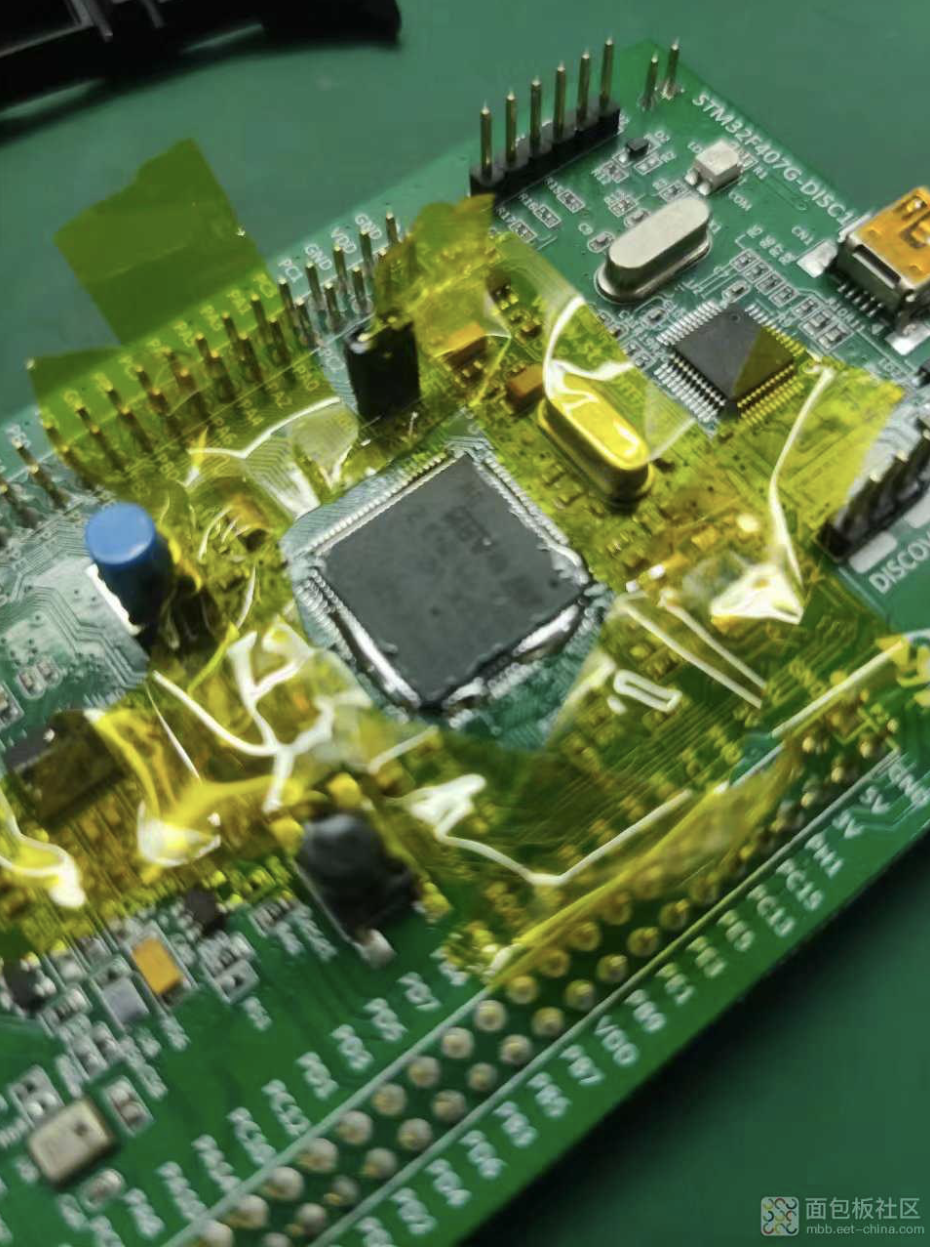
Starting the SolderingThe first step is to cover the area around the chip with high-temperature tape to protect nearby components during soldering.
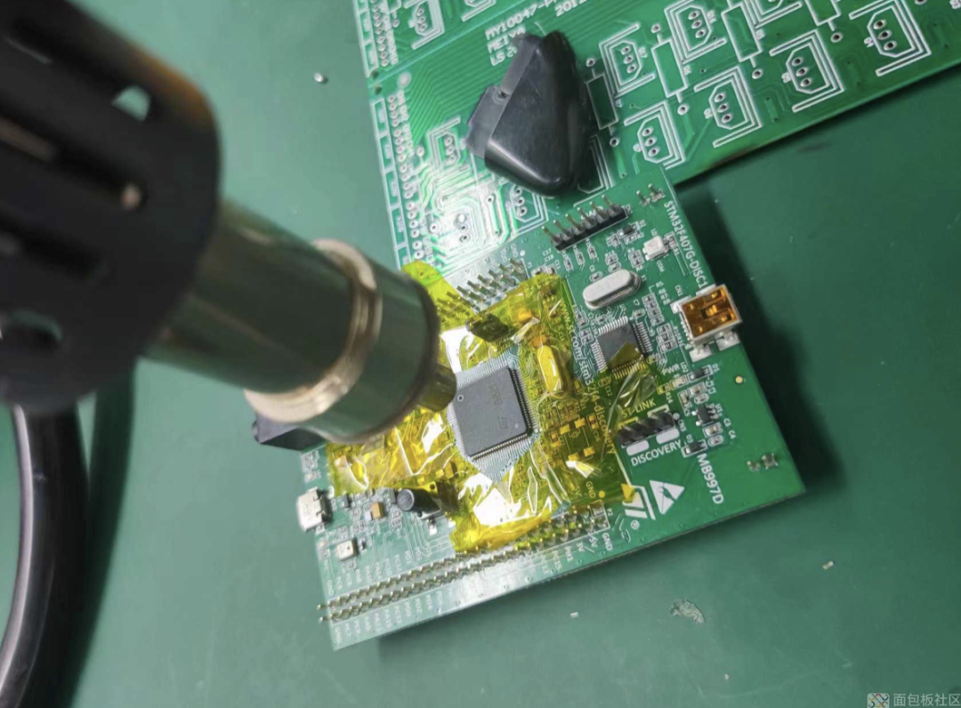
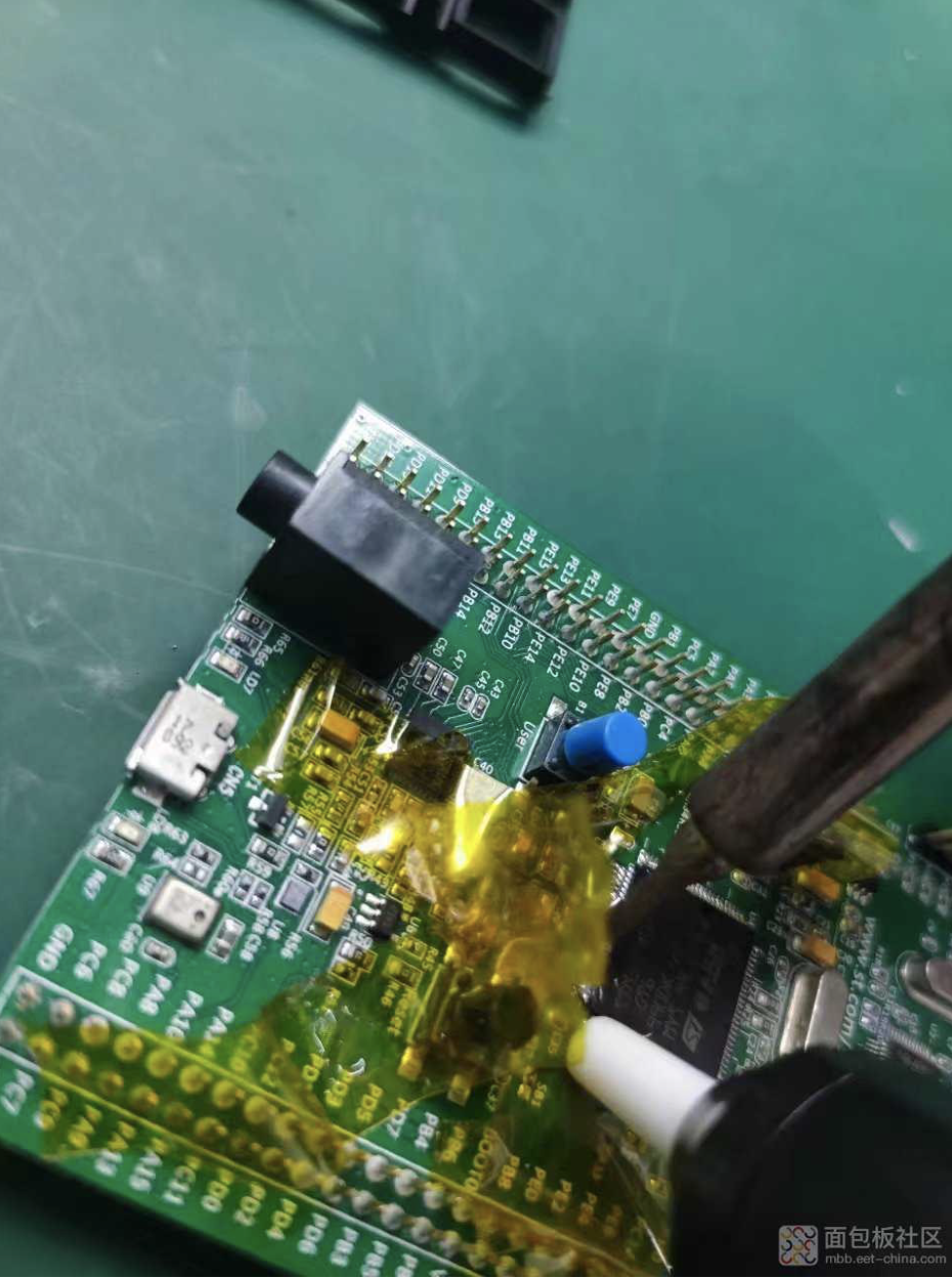
Use the hot air gun to remove the MCU, rotating slowly around the edges without rushing. Maintain a temperature of around 360°, and use tweezers to gently test if it has loosened. If it has, use the tweezers to pry it off.
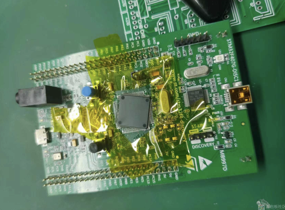
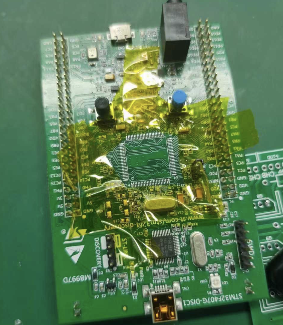
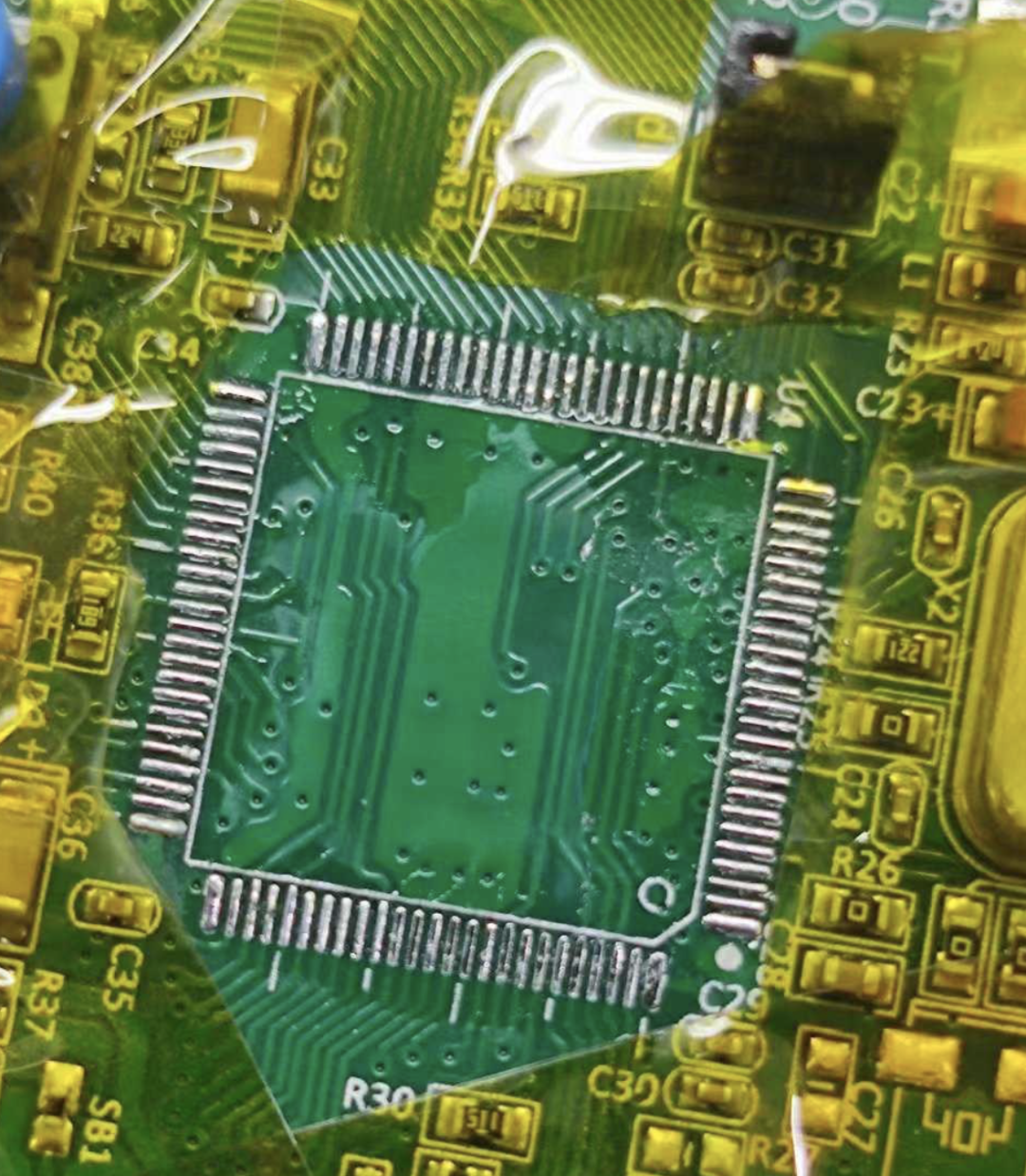
Here’s the result after removing it.
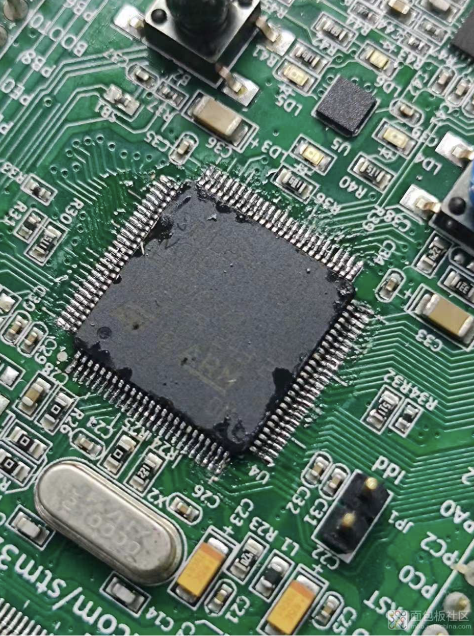
Next, use the soldering iron to flatten the pads, scraping them clean. You can add a bit of solder before scraping, and then clean it with alcohol.
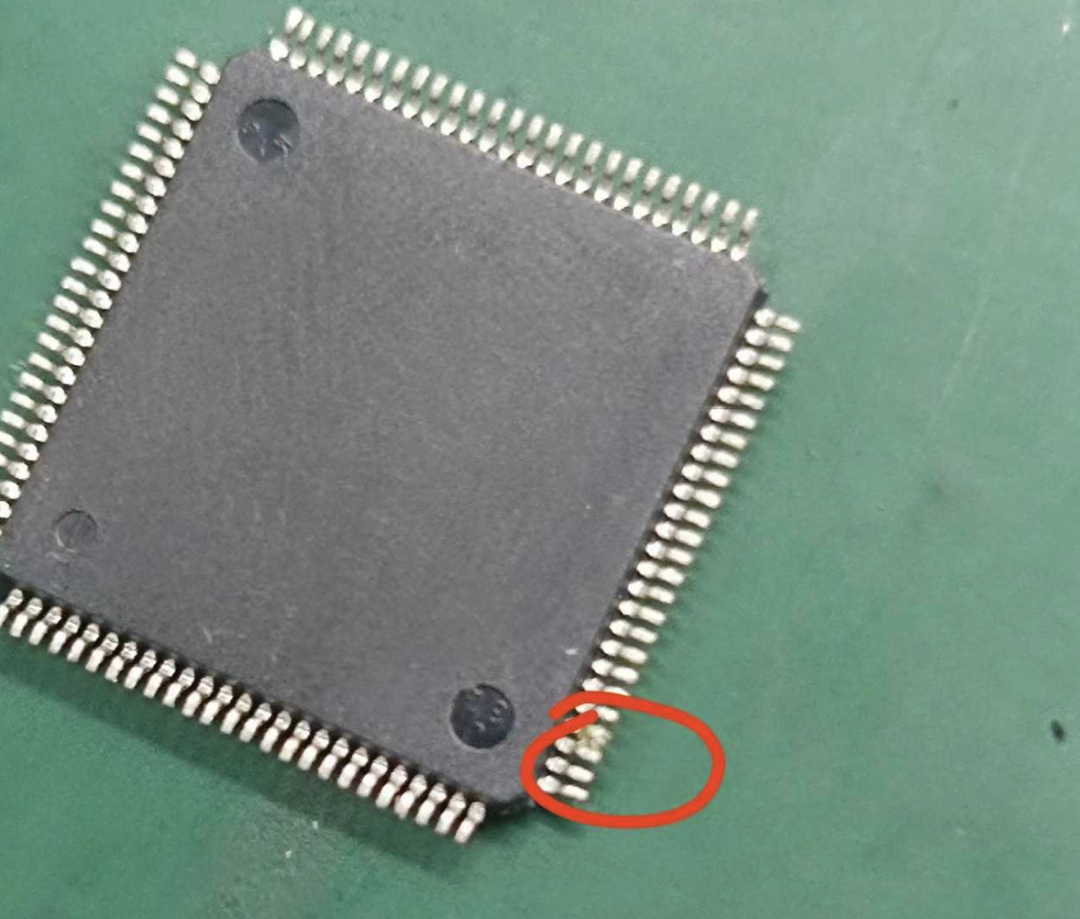
 Then place the MCU on the pads, aligning it carefully. Alignment is crucial, so take your time to adjust it with tweezers, ensuring it is straight. I noticed that the MCU and pads were not perfectly aligned, raising my suspicion that it might not only be a refurbished item but possibly a counterfeit. I chuckled to myself.
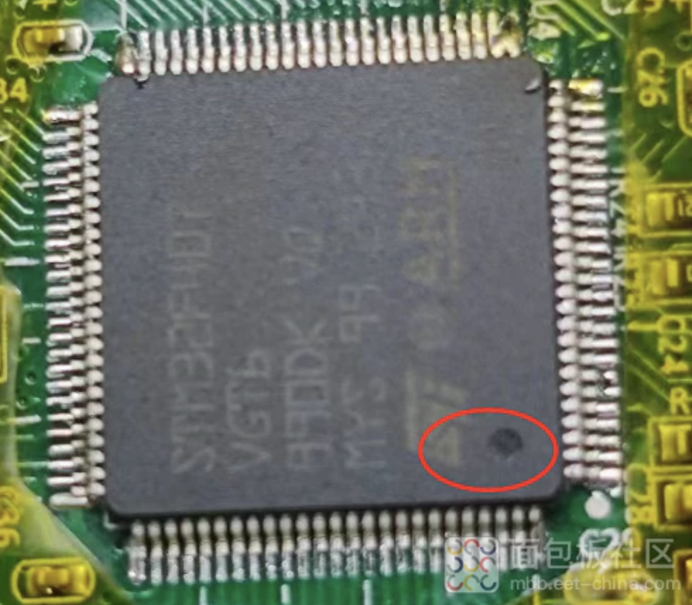
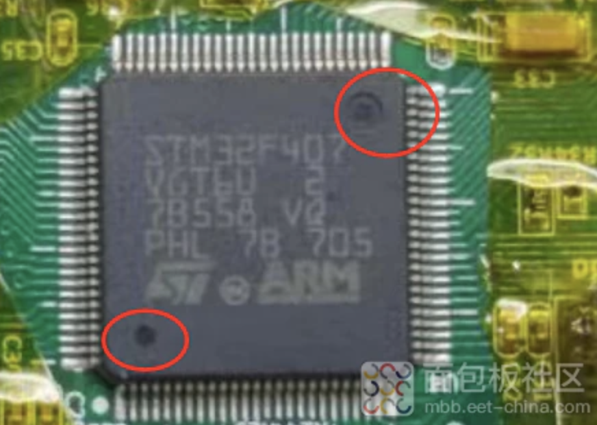
Upon closer inspection, I noticed that the original had two marks, while the one I bought only had one, and the silkscreen was also different.
At this point, there was no turning back; I had to push through.After aligning, I first used solder to secure the corners, being careful not to touch the pins to avoid misalignment.Then, I applied a generous amount of solder, dragging it along the edges several times. Don’t be stingy; we have plenty of solder, and the more solder there is, the better the flow. Finally, I dragged the solder to one side and used the solder sucker to remove the excess.
 Here’s the final result; I checked for any short circuits.
Finally, I cleaned it with alcohol.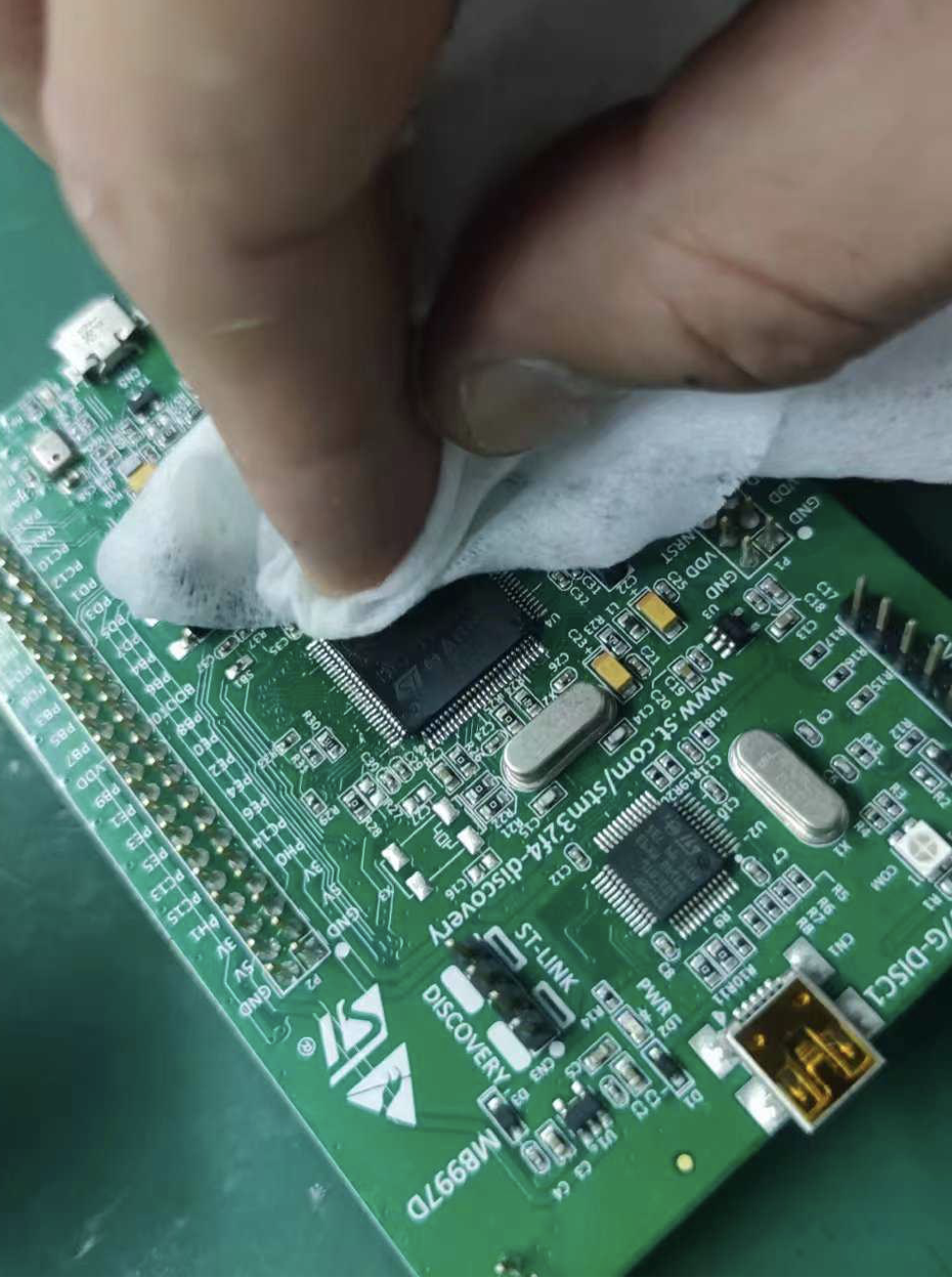 The final result looks decent. If I had some board cleaning solution, it would look even better. The surrounding pins could also be flattened with a soldering iron, but we won’t worry too much about appearances; let’s test it first, as I have a feeling this chip might not be very reliable.
After connecting the USB cable and ST-LINK, the chip can be recognized. To find out whether it is a counterfeit, stay tuned for the next update.