Electronic Scale Design Simulation Using Proteus

Electronic Scale Design Simulation Using Proteus

DJI drones, Fluke multimeters, Xiaomi phones, Huawei watches are waiting for you!

👆 The Breadboard Community DIY event is ongoing!
This design is from ErZhe Technology’s Proteus series for electronic scales, mainly used in vegetable markets. It can set prices and calculate amounts based on price and weight. This design uses the Proteus simulation software, with AT89C51 as the main controller, ADC0832 chip for ADC conversion, and LCD1602 display. A matrix keyboard is designed for price input. The design difficulty is rated at 3 stars (out of 5). First, design the circuit diagram; since there are not many modules, the interfaces can be assigned freely. The circuit simulation diagram is shown in Figure 1.
Electronic Scale Design Simulation Using Proteus
Figure 1. The design needs to be carried out step by step. Generally, prioritize the human-computer interaction module at the beginning. Here, we prioritize the design of the LCD1602. The driver program is as follows:
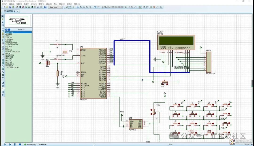
void wrc(uint8 c){     delay(1);     rs=0;     rw=0;     e=0;     P0=c;     e=1;     delay(1);     e=0;}void wrd(uint8 dat){     delay(1);     rs=1;     rw=0;     e=0;     P0=dat;     e=1;     delay(1);     e=0;     rs=0;}void init(){            delay(1);     wrc(0x38);     wrc(0x38);     wrc(0x38);     wrc(0x06);     wrc(0x0c);     wrc(0x01);}
With the screen display ready, we can design the other modules. The priority for the buttons and ADC is about the same, so we can choose freely. Here, we prioritize the design of the ADC0832 module, with the following code:
unsigned char A_D(unsigned char CH)    //AD function{   unsigned char i,adval,test; //define local variables and initialize   adval=0x00;   test=0x00;   DI=1;                       //DI initial high level before the first clock pulse's falling edge, indicating the start signal   _nop_();                                 CS=0;                       //chip select   _nop_();   Clk=1;                      //clk rising edge, start bit written in   _nop_();   if(CH==0x00)                //select channel 0   {       Clk=0;                  //clk low level       DI=1;                                    _nop_();       Clk=1;                  //clk rising edge, first bit of channel 0 written in       _nop_();       Clk=0;       DI=1;       _nop_();       Clk=1;                   //clk rising edge, second bit of channel 0 written in       _nop_();   }   else   {       Clk=0;       DI=1;       _nop_();       Clk=1;                    //clk rising edge, first bit of channel 1 written in       _nop_();       Clk=0;       DI=1;       _nop_();                   //clk rising edge, second bit of channel 1 written in       Clk=1;       _nop_();   }   Clk=0;   DI=1;   for(i=0;i<8;i++)               //read eight AD values from high to low   {       _nop_();       adval<<=1;       Clk=1;       _nop_();       Clk=0;       if(DO)           adval|=0x01;       else           adval|=0x00;   }   for(i=0;i<8;i++)   {                       test>>=1;                   //read eight AD values from low to high                       if(DO)           test|=0x80;         else                         test|=0x00;           _nop_();           Clk=1;           _nop_();           Clk=0;   }   if(adval==test)    dat=test;    //if both read values are equal, assign the read number to DAT   _nop_();   CS=1;   DO=1;   Clk=1;   return dat;    }
Finally, let’s design the matrix keyboard, which is also quite simple and generally known to those who have studied microcontrollers. The code is as follows:
uint8 keyscan()           //key scan program{    uint8 h,l,value;    P1=0x0f;    h=P1&0x0f;    if(h!=0x0f)    {         delay(1);         if(h!=0x0f)         {             h=P1&0x0f;             l=P1|0xf0;             P1=l;             l=P1&0xf0;             h=P1&0x0f;             value=h+l;                 }         return value;    }}
With all the drivers ready, the last step is to implement the logic. Since the logic code is quite lengthy, I won’t paste it here. Let’s take a look at the effect!
Electronic Scale Design Simulation Using Proteus
Author: ErZhe Technology Source: https://mbb.eet-china.com/forum/topic/90048_1_1.html
The Breadboard Community DIY event is ongoing!👇
https://mbb.eet-china.com/forum/topic/147007_1_1.html
Community
Activities
Event
Ongoing
Electronic Scale Design Simulation Using Proteus
Share your DIY electronic design on the Breadboard Community blog/forum, and add the tag 【Electronic DIY】 when publishing your article. There is no word limit, and articles will be reviewed by the community for rich rewards!
↓ Scan the code to participate
Electronic Scale Design Simulation Using Proteus
【Prize Settings】
First Prize (1 winner): DJI Neo drone, Xiaomi Redmi Note 13 Pro, Hikvision NAS Mage 20 PRO… (choose one)Second Prize (unlimited number of winners): Fluke F15B PRO MAX multimeter, Huawei WATCH FIT 2… (choose one)Third Prize (unlimited number of winners):Xiaomi Mi Band 9 NFC version, Xiaomi mini massage gun 2C, electronic tools worth ¥300… (choose one)
Participation Prize: All participants will receive a reward of 500 E-coins!
Over Ten Thousand Reward: If a single article/video reaches over ten thousand views on the MBB WeChat account, each article will receive a reward of 1000 E-coins (E-coins can be exchanged for prizes in the E-coin mall, data statistics deadline is February 28, 2025, only the first 20 articles are eligible, rewards are sorted by the time of publication in the MBB community, with a personal cumulative cap of 10,000 E-coins).
E-coins can be exchanged for commonly used tools and exquisite gifts in the E-coin mall (https://estore.eet-china.com/), such as tweezers, development boards, oscilloscopes, toolboxes, storage boxes, etc.
Electronic Scale Design Simulation Using Proteus
【Article Requirements】
1、Content must beoriginal, related to the electronics industry, and must be published on the internet for the first time.
2、Content should include: design ideas, finished product display (such as circuit principles, functional display, cost control plans or lists, code, etc.). Content involving core intellectual property can be omitted.
3. During the event, the same ID can participate multiple times, and multiple works can accumulate scores under the same quality conditions.
Event duration: November 13, 2024 – February 13, 2025
Electronic Scale Design Simulation Using ProteusClick to read the original text, to learn more about the event!

Leave a Comment