In this issue, we will briefly discuss Dynamic Power Management (DPM) in the NVDC Charger. Let’s quickly review the principles of NVDC: By adding a switch between the system and the battery, when the battery voltage Vbat<Vsys_min, the system voltage Vsys can be maintained at a fixed value through DC/DC conversion.
Dynamic Power Management (DPM) is a mechanism that dynamically adjusts power distribution in battery management ICs to optimize charging efficiency, prevent system crashes, and ensure stable power supply.
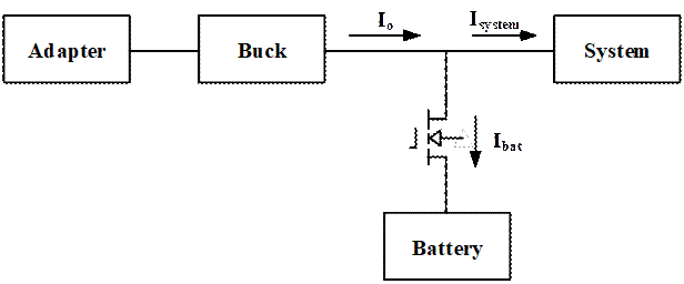
Under normal operating conditions, when the adapter’s output capability is sufficient, it can simultaneously power the system and charge the battery; when the system load suddenly increases, in order to meet the maximum current limit specified by USB and avoid overloading the adapter, the chip needs to monitor the input current and input voltage. When the input current exceeds the input current limit (IINDPM) or the input voltage falls below the input voltage limit (VINDPM), the charging current will be reduced.↓
Next, let’s analyze the case where the battery voltage Vbat<Vsys_min:
Assuming Vbat=3.2V, Vsys_min is set to 3.5V, input current limit is 1.2A, during normal charging, ICHG=2.8A, Vsys is maintained at 3.6V through DC/DC conversion, and the BATFET operates in the CC (constant current charging) loop; as Isys gradually increases, IIN reaches the current limit of 1.2A, thus the input voltage drops, and when it reaches the VINDPM value, the input voltage is maintained at the VINDPM value, at this point, DC/DC operates in the DPM loop, and the BATFET operates in the Vsys_min loop (to maintain system voltage), and the charging current decreases.
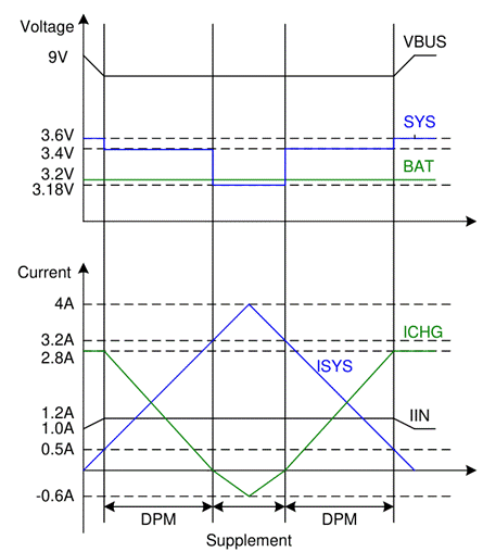
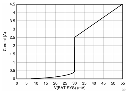
When the charging current has decreased to 0, and Isys continues to increase, due to insufficient power supply, Vsys will drop, and when Vsys falls below a certain value of Vbat, it will enter the boost mode, BATFET will turn on, and the battery will start discharging; when the discharge current is small, the gate drive voltage is adjusted to maintain VDS at 30mV, which can prevent oscillation from entering and exiting the boost mode. As the discharge current increases, the gate is adjusted to a higher voltage to reduce the on-resistance until fully turned on. At this point, VDS increases linearly with the discharge current.