- 1. Main Registers of MPU6050
- 1.1 Initialization Registers and Their Settings
- 1.2 Data Registers
- 2. Hardware Connections
- 3. Device Tree Configuration
- 4. Writing Driver Code
- 4.1 i2c_mpu6050.h
- 4.2 mpu6050.c
- 5. Timing Observations of Initialization Functions in Probe
- 5.1 Overall Timing
- 5.2 CLK
- 5.3 Host Writing One Byte to Slave
- 5.4 Host Reading One Byte from Slave
1. Main Registers of MPU6050
1.1 Initialization Registers and Their Settings
| Register Name | Address | Setting Value | Function Overview |
|---|---|---|---|
<span>PWR_MGMT_1</span> |
0x6B | 0x00 | Wake up the device, use internal clock |
<span>SMPLRT_DIV</span> |
0x19 | 0x07 | Set sample rate to 125Hz |
<span>CONFIG</span> |
0x1A | 0x06 | Set low-pass filter, bandwidth of 5Hz |
<span>ACCEL_CONFIG</span> |
0x1C | 0x01 | Set accelerometer range to ±4g |
1.2 Data Registers
The following are the registers that store the raw data from the accelerometer and gyroscope:
| Register Name | Address | Function |
|---|---|---|
<span>ACCEL_XOUT_H</span> |
<span>0x3B</span> |
X-axis high 8 bits |
<span>ACCEL_XOUT_L</span> |
<span>0x3C</span> |
X-axis low 8 bits |
<span>ACCEL_YOUT_H</span> |
<span>0x3D</span> |
Y-axis high 8 bits |
<span>ACCEL_YOUT_L</span> |
<span>0x3E</span> |
Y-axis low 8 bits |
<span>ACCEL_ZOUT_H</span> |
<span>0x3F</span> |
Z-axis high 8 bits |
<span>ACCEL_ZOUT_L</span> |
<span>0x40</span> |
Z-axis low 8 bits |
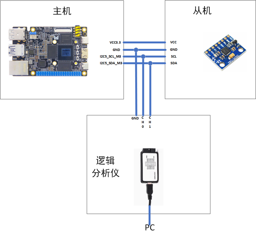
2. Hardware Connections
3. Device Tree Configuration
Add the following content to the main device tree:
&i2c5 {
    status = "okay";  // Enable i2c5
    pinctrl-names = "default";
    pinctrl-0 = <&i2c5m3_xfer>;  // Reuse m3 pins
    #address-cells = <1>;  // Set reg content as address
    #size-cells = <0>;
    mpu6050:mpu6050@68 {
        compatible = "invensense,mpu6050";
        reg = <0x68>;
        status = "okay";
    };
};
Compile the device tree and copy it to the development board, then check the status of i2c5 and the node information under i2c5:
cat@lubancat:/proc/device-tree$ grep -r "mpu"
grep: __symbols__/mpu6050: matches binary file
grep: i2c@fead0000/mpu6050@68/compatible: matches binary file
grep: i2c@fead0000/mpu6050@68/name: matches binary file
cat@lubancat:/proc/device-tree$ cd i2c@fead0000/
cat@lubancat:/proc/device-tree/i2c@fead0000$ ls
'#address-cells'   compatible         dcphy1-ov13850@10   dcphy1-ov8858@36   name        pinctrl-names   resets
    clock-names       dcphy1-dw9714@c    dcphy1-ov5647@36    interrupts         phandle     reg            '#size-cells'
    clocks            dcphy1-imx415@1a   dcphy1-ov5648@36    mpu6050@68         pinctrl-0   reset-names     status
cat@lubancat:/proc/device-tree/i2c@fead0000$ cat mpu6050@68/compatible
invensense,mpu6050
4. Writing Driver Code
The main functions used are<span>i2c_master_send</span> and <span>i2c_master_recv</span>.
4.1 i2c_mpu6050.h
#ifndef I2C_MPU6050_H
#define I2C_MPU6050_H

// Macro Definitions
#define SMPLRT_DIV                                  0x19
#define CONFIG                                      0x1A
#define GYRO_CONFIG                                 0x1B
#define ACCEL_CONFIG                                0x1C
#define ACCEL_XOUT_H                                0x3B
#define ACCEL_XOUT_L                                0x3C
#define ACCEL_YOUT_H                                0x3D
#define ACCEL_YOUT_L                                0x3E
#define ACCEL_ZOUT_H                                0x3F
#define ACCEL_ZOUT_L                                0x40
#define TEMP_OUT_H                                  0x41
#define TEMP_OUT_L                                  0x42
#define GYRO_XOUT_H                                 0x43
#define GYRO_XOUT_L                                 0x44
#define GYRO_YOUT_H                                 0x45
#define GYRO_YOUT_L                                 0x46
#define GYRO_ZOUT_H                                 0x47
#define GYRO_ZOUT_L                                 0x48
#define PWR_MGMT_1                                  0x6B
#define WHO_AM_I                                    0x75
#define SlaveAddress                                0xD0
#define Address                                     0x68                  // MPU6050 address
#define I2C_RETRIES                                 0x0701
#define I2C_TIMEOUT                                 0x0702
#define I2C_SLAVE                                   0x0703       // IIC slave device address setting
#define I2C_BUS_MODE                                0x0780

#endif
4.2 mpu6050.c
#include <linux/init.h>
#include <linux/module.h>
#include <linux/platform_device.h>
#include <linux/of.h>
#include <linux/fs.h>
#include <linux/cdev.h>
#include <linux/kdev_t.h>
#include <linux/slab.h>
#include <linux/gpio.h>
#include <linux/gpio/consumer.h> // Add this header file
#include <linux/delay.h>
#include <linux/i2c.h>

#include "i2c_mpu6050.h"

struct mpu6050_private{
    int dev_num;
    struct cdev mpu6050_cdev;
    struct class *mpu6050_class;
    struct device *mpu6050_device;
    char *cdev_name;
    char *class_name;
    char *device_name;
};

static struct mpu6050_private mpu6050={
    .cdev_name="mpu6050_cdev",
    .class_name="mpu6050_class",
    .device_name="mpu6050_device",
};

static struct i2c_client *mpu6050_client;

int mpu6050_open(struct inode *node, struct file *file)
{
    printk(KERN_EMERG"Enter mpu6050_open function\n");
    return 0;
}

ssize_t mpu6050_read(struct file *file, char __user *userBuf, size_t size, loff_t *offset)
{
    char tx_buf[1];
    char high,low;
    char rx_buf[6];
    // First send address, then read high and low bytes
    tx_buf[0]=ACCEL_XOUT_H;
    if(i2c_master_send(mpu6050_client,tx_buf,1)>0)
        i2c_master_recv(mpu6050_client,&high,1);
    else
        printk(KERN_EMERG"ACCEL_XOUT_H read error\n");
    tx_buf[0]=ACCEL_XOUT_L;
    if(i2c_master_send(mpu6050_client,tx_buf,1)>0) i2c_master_recv(mpu6050_client,&low,1);
    rx_buf[0]=high<<8|low;

    tx_buf[0]=ACCEL_YOUT_H;
    if(i2c_master_send(mpu6050_client,tx_buf,1)>0) i2c_master_recv(mpu6050_client,&high,1);
    tx_buf[0]=ACCEL_YOUT_L;
    if(i2c_master_send(mpu6050_client,tx_buf,1)>0) i2c_master_recv(mpu6050_client,&low,1);
    rx_buf[1]=high<<8|low;

    tx_buf[0]=ACCEL_ZOUT_H;
    if(i2c_master_send(mpu6050_client,tx_buf,1)>0) i2c_master_recv(mpu6050_client,&high,1);
    tx_buf[0]=ACCEL_ZOUT_L;
    if(i2c_master_send(mpu6050_client,tx_buf,1)>0) i2c_master_recv(mpu6050_client,&low,1);
    rx_buf[2]=high<<8|low;

    tx_buf[0]=GYRO_XOUT_H;
    if(i2c_master_send(mpu6050_client,tx_buf,1)>0) i2c_master_recv(mpu6050_client,&high,1);
    tx_buf[0]=GYRO_XOUT_L;
    if(i2c_master_send(mpu6050_client,tx_buf,1)>0) i2c_master_recv(mpu6050_client,&low,1);
    rx_buf[3]=high<<8|low;

    tx_buf[0]=GYRO_YOUT_H;
    if(i2c_master_send(mpu6050_client,tx_buf,1)>0) i2c_master_recv(mpu6050_client,&high,1);
    tx_buf[0]=GYRO_YOUT_L;
    if(i2c_master_send(mpu6050_client,tx_buf,1)>0) i2c_master_recv(mpu6050_client,&low,1);
    rx_buf[4]=high<<8|low;

    tx_buf[0]=GYRO_ZOUT_H;
    if(i2c_master_send(mpu6050_client,tx_buf,1)>0) i2c_master_recv(mpu6050_client,&high,1);
    tx_buf[0]=GYRO_ZOUT_L;
    if(i2c_master_send(mpu6050_client,tx_buf,1)>0) i2c_master_recv(mpu6050_client,&low,1);
    rx_buf[5]=high<<8|low;

    if(copy_to_user(userBuf,rx_buf,sizeof(rx_buf)))
    {
        printk(KERN_EMERG"copy_to_user error\n");
        return -1;
    }

    return 0;
}
ssize_t mpu6050_write(struct file *file, const char __user *userBuf, size_t size, loff_t *offset)
{
    return size;
}
static struct file_operations mpu6050_ops={
    .open=mpu6050_open,
    .read=mpu6050_read,
    .write=mpu6050_write,
};

void mpu6050_conf(void)
{
    int error = 0;
    char buf[2]; // Address to write + data to write
    buf[0]=PWR_MGMT_1;
    buf[1]=0X00;
    error+=i2c_master_send(mpu6050_client,buf, 2);
    buf[0]=SMPLRT_DIV;
    buf[1]=0X07;
    error+=i2c_master_send(mpu6050_client,buf, 2);
    buf[0]=CONFIG;
    buf[1]=0X06;
    error+=i2c_master_send(mpu6050_client,buf, 2);
    buf[0]=ACCEL_CONFIG;
    buf[1]=0X01;
    error+=i2c_master_send(mpu6050_client,buf, 2);

 if (error < 0)
 {
  /* Initialization error */
  printk(KERN_DEBUG "mpu6050_init error \n");
 }
}

int mpu6050_probe(struct i2c_client *client)
{
    int ret;
    printk(KERN_EMERG"Enter mpu6050_probe function\n");

    mpu6050_client=client;
    // Allocate character device number
    ret = alloc_chrdev_region(&mpu6050.dev_num, 0, 1, mpu6050.cdev_name);
    if (ret < 0)
    {
        printk(KERN_EMERG"alloc_chrdev_region error\n");
        return -EAGAIN;
    }
    // Initialize character device
    cdev_init(&mpu6050.mpu6050_cdev, &mpu6050_ops);
    mpu6050.mpu6050_cdev.owner=THIS_MODULE;
    cdev_add(&mpu6050.mpu6050_cdev, mpu6050.dev_num, 1);

    // Create device class
    mpu6050.mpu6050_class=class_create(THIS_MODULE,mpu6050.class_name);
    if (IS_ERR(mpu6050.mpu6050_class))
    {
        printk(KERN_EMERG"class_create error\n");
        return -EAGAIN;
    }

    // Create device
    mpu6050.mpu6050_device= device_create(mpu6050.mpu6050_class, NULL, mpu6050.dev_num, NULL, mpu6050.device_name);
    if (IS_ERR(mpu6050.mpu6050_device))
    {
        printk(KERN_EMERG"device_create error\n");
        return -EAGAIN;
    }

    // Initialize mpu6050
    mpu6050_conf();
    return 0;
}
void mpu6050_remove(struct i2c_client *client)
{
}
struct of_device_id mpu6050_match_table[]={
    {.compatible="invensense,mpu6050"},
    {},
};
const struct i2c_device_id mpu6050_id_table[]={
    {"mpu6050",0},
    {}
};

static struct i2c_driver mpu6050_driver={
    .id_table=mpu6050_id_table,
    .probe_new=mpu6050_probe,
    .remove=mpu6050_remove,
    .driver={
        .owner=THIS_MODULE,
        .name="mpu6050",
        .of_match_table=mpu6050_match_table,
    },
};

static int mpu6050_init(void)
{
    int ret;
    printk(KERN_EMERG"Enter mpu6050_init function\n");
    ret=i2c_register_driver(THIS_MODULE,&mpu6050_driver);

    if(ret<0)
    {
        printk(KERN_EMERG"i2c_register_driver error\n");
        return -1;
    }
    return 0;
}
static void mpu6050_exit(void)
{
    device_destroy(mpu6050.mpu6050_class,mpu6050.dev_num);
    class_destroy(mpu6050.mpu6050_class);
    cdev_del(&mpu6050.mpu6050_cdev);
    unregister_chrdev_region(mpu6050.dev_num,1);
    i2c_del_driver(&mpu6050_driver);
}


module_init(mpu6050_init);
module_exit(mpu6050_exit);

MODULE_AUTHOR("Fle");
MODULE_LICENSE("GPL v2");
5. Timing Observations of Initialization Functions in Probe
5.1 Overall Timing
void mpu6050_conf(void)
{
    int error = 0;
    char buf[2]; // Address to write + data to write
    buf[0]=PWR_MGMT_1;
    buf[1]=0X00;
    error+=i2c_master_send(mpu6050_client,buf, 2);
    buf[0]=SMPLRT_DIV;
    buf[1]=0X07;
    error+=i2c_master_send(mpu6050_client,buf, 2);
    buf[0]=CONFIG;
    buf[1]=0X06;
    error+=i2c_master_send(mpu6050_client,buf, 2);
    buf[0]=ACCEL_CONFIG;
    buf[1]=0X01;
    error+=i2c_master_send(mpu6050_client,buf, 2);

 if (error < 0)
 {
  /* Initialization error */
  printk(KERN_DEBUG "mpu6050_init error \n");
 }
}
The timing corresponding to the above code is shown below: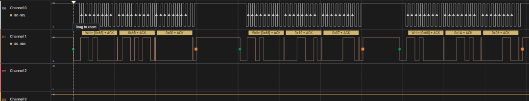
5.2 CLK
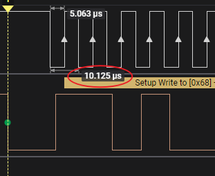
One CLK cycle is 10us, which corresponds to a transmission rate of 100kHz.
5.3 Host Writing One Byte to Slave
buf[0]=PWR_MGMT_1; //0x6B
buf[1]=0X00;
error+=i2c_master_send(mpu6050_client,buf, 2);
The timing corresponding to the above code is as follows: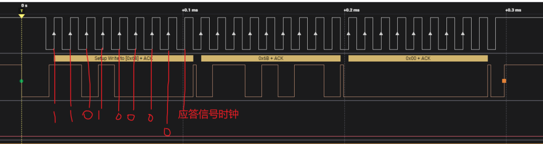
From the figure, it can be seen that the transmitted 7 bits are 0x1101000=0x01101000=0x68, which is the address of the MPU6050.
The 8th bit is 0, indicating a write operation, as the host needs to send data to the slave.
At the 9th clock, the host has released the SDA bus, and the slave pulls it low, indicating ACK.
It can be seen that after executing the <span>i2c_master_send</span> function, the CLK goes high, and the SDA shows a rising edge, which is the stop signal sent by the host.
5.4 Host Reading One Byte from Slave
// First send address, then read high and low bytes
tx_buf[0]=ACCEL_XOUT_H; //0x3B
if(i2c_master_send(mpu6050_client,tx_buf,1)>0)
    i2c_master_recv(mpu6050_client,&high,1);
else
    printk(KERN_EMERG"ACCEL_XOUT_H read error\n");
The timing for the above code is as follows:
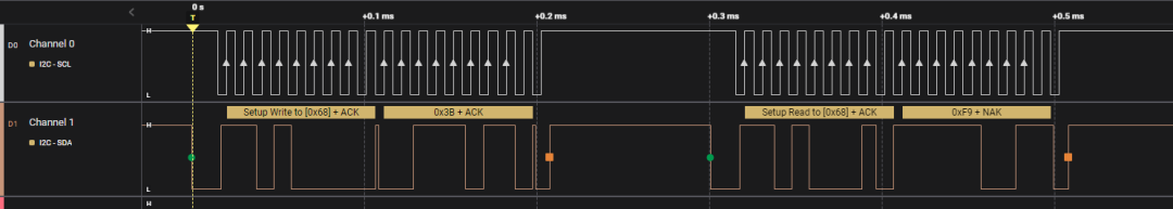
Before reading, it is necessary to first determine the device address and the register address to read, so in fact, the <span>i2c_master_send</span> function sends two bytes of data consecutively, one is 0x68 write, and the other is 0x3B write, then 0x68 read, and then the SDA bus is handed over to the slave, which transmits data 0xF9. It is worth noting that the last is a NAK signal, which is sent by the host to inform the slave that the reading is complete.