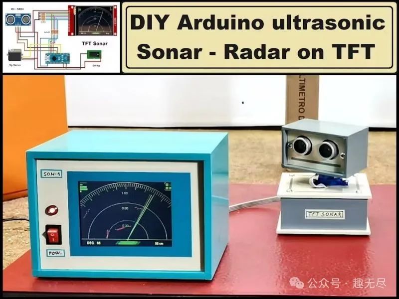
The ultrasonic sonar is a device that measures the distance to an object by emitting sound waves at a frequency above the human hearing threshold (typically above 20KHz). Its working principle involves sending out sound waves and measuring the time it takes for the sound waves to bounce back after hitting an object. By calculating the time difference between sending and receiving the sound waves and utilizing the speed of sound in air, the distance to the object can be determined. In some of my previous videos, you can see various constructions of such devices with special functions. They all display the results on a computer monitor through additional programs written in Processing.
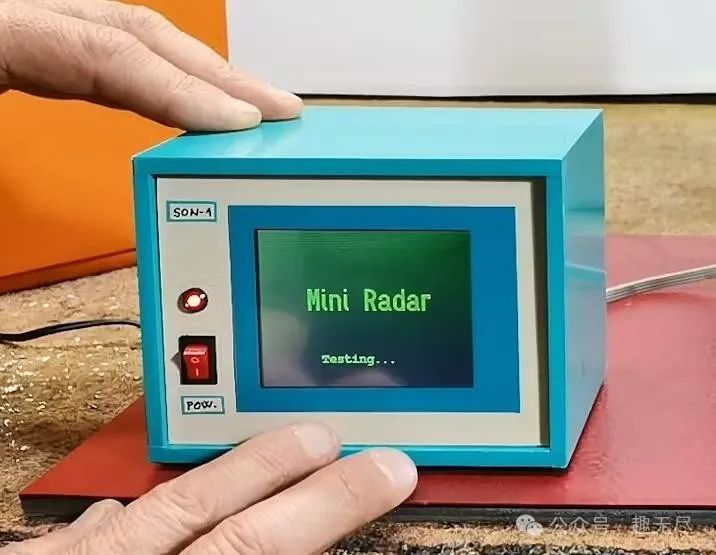
This time, I will introduce you to a simple method to create a standalone sonar device, which displays the results directly on a TFT color display in the form of a radar image, hence it is often mistakenly referred to as radar instead of sonar.
Component List
– Arduino Nano R3 × 1
– TFT display with a resolution of 240 x 320 pixels, equipped with ILI9341 driver chip × 1
– HC-SR04 ultrasonic sensor × 1
– Small 9g servo motor × 1
– 2.2K ohm resistors × 5
– 3.3K ohm resistors × 5
Tools used:
– Soldering iron
– Lead-free solder wire
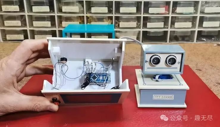
The servo motor and ultrasonic sensor are installed in a box I kept from a previous project and connected to the main box via a flat cable.
Design and Assembly
The idea came to me when I accidentally saw an image online, and after some research, I found a related project on GitHub. The original project was made on a 1.8-inch display, which indeed had a very small display area for this purpose. Therefore, I rewrote the code to make it suitable for a larger 3.2-inch TFT display, allowing for clearer image display.
Now, let’s delve into the excellent performance of this device in real application scenarios:
First, to ensure measurement accuracy, I carefully separated the ultrasonic sensor from the servo motor and meticulously calibrated the correspondence between the graphical display and the actual distance to the object. You will find that the distance displayed on the screen aligns remarkably well with the actual measured distance.
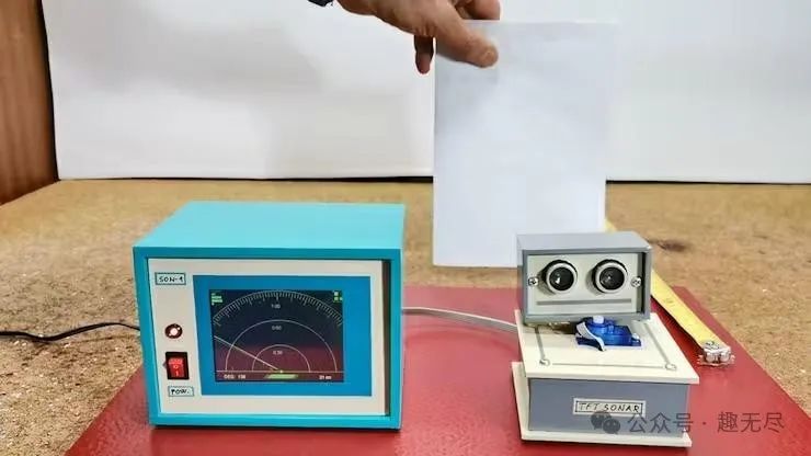
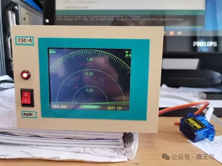
Next, we securely mounted the sensor on the servo motor and placed an obstacle to be detected. After powering on, the servo motor first conducted a smooth test, followed by the display presenting a radar-like scanning interface, and began precise scanning work.
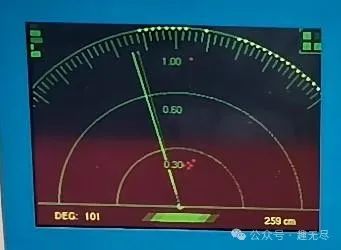
The obstacle is marked on the screen with a prominent red dot. The lower left corner of the screen clearly displays the current scanning area, while the right side updates in real-time the distance between the sensor and the obstacle, with precision down to centimeters. To present distance information more intuitively, we specially designed three green arcs that adjust dynamically with distance, allowing users to grasp the actual distance at a glance. When the nearest obstacle’s distance exceeds 1 meter, a yellow warning point will appear on the last arc, reminding the user that they have exceeded the scanning range. The scanning process starts from 180 degrees and gradually narrows to 0 degrees, then expands back to 180 degrees, achieving full coverage.
To ensure stable operation of the device, we recommend using an external power supply; however, for user convenience, we also provide the option to power it through the Arduino’s USB interface. Additionally, users can easily adjust all display colors in the code according to their preferences to meet different visual needs.
Finally, I would like to summarize this device briefly. Compared to most similar products, it does not rely on a computer monitor to display scanning results, eliminating the need for additional applications and cumbersome code. It is easy to make, visually appealing, and operates completely independently, making it an ideal choice for both beginners and seasoned DIY enthusiasts. However, for a better user experience, it is recommended to integrate all components into a compact case and equip it with an inclined front display screen to simulate a real radar system, providing users with a more realistic experience.
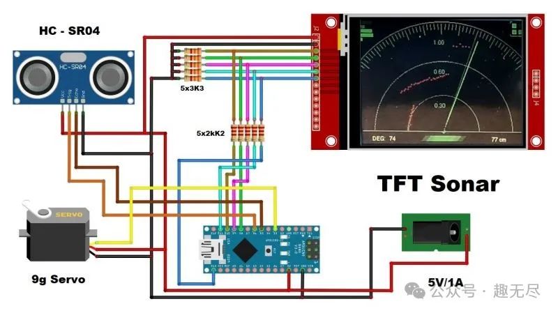
Wiring Diagram
Code
Below is the complete source code, which can also be downloaded from the project file repository: https://make.quwj.com/project/521
#include <Servo.h> #include <SPI.h> #include "Ucglib.h" #define trigPin 6 #define echoPin 5 #define ServoPin 3 int Ymax = 240; int Xmax = 320; int Xcent = Xmax / 2; int base = 210; int scanline = 185; Servo baseServo; //Ucglib_ILI9341_18x240x320_SWSPI ucg(/*sclk=*/ 13, /*data=*/ 11, /*cd=*/ 9, /*cs=*/ 10, /*reset=*/ 8); Ucglib_ILI9341_18x240x320_HWSPI ucg(/*cd=*/ 9, /*cs=*/ 10, /*reset=*/ 8); void setup(void){ ucg.begin(UCG_FONT_MODE_SOLID); ucg.setRotate90(); pinMode(trigPin, OUTPUT); pinMode(echoPin, INPUT); Serial.begin(115200); baseServo.attach(ServoPin); ucg.setFontMode(UCG_FONT_MODE_TRANSPARENT); ucg.setColor(0, 0, 100, 0); ucg.setColor(1, 0, 100, 0); ucg.setColor(2, 20, 20,20); ucg.setColor(3, 20, 20, 20); ucg.drawGradientBox(0, 0, 320, 240); ucg.setPrintDir(0); ucg.setColor(0, 5, 0); ucg.setPrintPos(70,120); ucg.setFont(ucg_font_logisoso32_tf); ucg.print("Mini Radar"); ucg.setColor(0, 255, 0); ucg.setPrintPos(70,120); ucg.print("Mini Radar"); ucg.setFont(ucg_font_courB14_tf); ucg.setColor(20, 255, 20); ucg.setPrintPos(90,200); ucg.print("Testing..."); baseServo.write(90); for(int x=0;x<180;x+=5) { baseServo.write(x); delay(50); } ucg.print("OK!"); delay(500); ucg.setColor(0,0, 0, 0); ucg.setColor(1,0, 0, 0); ucg.setColor(2,0, 0, 0); ucg.setColor(3,0, 0, 0); ucg.drawGradientBox(0, 0, 320, 240); delay(10); cls(); ucg.setFontMode(UCG_FONT_MODE_SOLID); ucg.setFont(ucg_font_helvR08_hr); } void cls(){ ucg.setColor(0, 0, 0, 0); for(int s=0;s<240;s++) { ucg.drawHLine(0,s,320); delay(1); } } int calculateDistance(){ long duration; digitalWrite(trigPin, LOW); delayMicroseconds(2); digitalWrite(trigPin, HIGH); delayMicroseconds(10); digitalWrite(trigPin, LOW); duration = pulseIn(echoPin, HIGH); return duration*0.034/2;} void fix_font() { ucg.setColor(0, 180, 0); ucg.setPrintPos(144,44); ucg.print("1.00"); ucg.setPrintPos(144,100); ucg.print("0.60"); ucg.setPrintPos(144,165); ucg.print("0.30"); } void fix(){ ucg.setColor(0, 180, 0); ucg.drawDisc(Xcent, base+1, 3, UCG_DRAW_ALL); ucg.drawCircle(Xcent, base+1, 210, UCG_DRAW_UPPER_LEFT); ucg.drawCircle(Xcent, base+1, 210, UCG_DRAW_UPPER_RIGHT); ucg.drawCircle(Xcent, base+1, 135, UCG_DRAW_UPPER_LEFT); ucg.drawCircle(Xcent, base+1, 135, UCG_DRAW_UPPER_RIGHT); ucg.drawCircle(Xcent, base+1, 70, UCG_DRAW_UPPER_LEFT); ucg.drawCircle(Xcent, base+1, 70, UCG_DRAW_UPPER_RIGHT); ucg.drawLine(0, base+1, Xmax,base+1); ucg.setColor(0, 180, 0); for(int i= 40;i < 300; i+=2) { if (i % 10 == 0) ucg.drawLine(185*cos(radians(i))+Xcent,base - 185*sin(radians(i)) , 205*cos(radians(i))+Xcent,base - 205*sin(radians(i))); else ucg.drawLine(195*cos(radians(i))+Xcent,base - 195*sin(radians(i)) , 205*cos(radians(i))+Xcent,base - 205*sin(radians(i))); } ucg.setColor(0,200,0); ucg.drawLine(0,0,0,36); for(int i= 0;i < 5; i++) { ucg.setColor(0,random(200)+50,0); ucg.drawBox(2,i*8,random(28)+3,6); } ucg.setColor(0,180,0); ucg.drawFrame(292,0,28,28); ucg.setColor(0,60,0); ucg.drawHLine(296,0,20); ucg.drawVLine(292,4,20); ucg.drawHLine(296,52,20); ucg.drawVLine(318,4,20); ucg.setColor(0,220,0); ucg.drawBox(296,4,8,8); ucg.drawBox(296,16,8,8); ucg.drawBox(308,16,8,8); ucg.setColor(0,100,0); ucg.drawBox(308,4,8,8); ucg.setColor(0,90,0); ucg.drawTetragon(124,220,116,230,196,230,204,220); ucg.setColor(0,160,0); ucg.drawTetragon(134,220,126,230,186,230,194,220); ucg.setColor(0,210,0); ucg.drawTetragon(144,220,136,230,176,230,184,220);} void loop(void){ int distance; fix(); fix_font(); for (int x=180; x > 4; x-=2){ baseServo.write(x); int f = x - 4; ucg.setColor(0, 255, 0); ucg.drawLine(Xcent, base, scanline*cos(radians(f))+Xcent,base - scanline*sin(radians(f))); f+=2; ucg.setColor(0, 128, 0); ucg.drawLine(Xcent, base, scanline*cos(radians(f))+Xcent,base - scanline*sin(radians(f))); f+=2; ucg.setColor(0, 0, 0); ucg.drawLine(Xcent, base, scanline*cos(radians(f))+Xcent,base - scanline*sin(radians(f))); ucg.setColor(0,200, 0); distance = calculateDistance(); if (distance < 100) { ucg.setColor(255,0,0); ucg.drawDisc(2.2*distance*cos(radians(x))+ Xcent,-2.2*distance*sin(radians(x))+base, 1, UCG_DRAW_ALL); } else { ucg.setColor(255,255,0); ucg.drawDisc(208*cos(radians(x))+Xcent,-208*sin(radians(x))+base, 1, UCG_DRAW_ALL); } Serial.print(x); Serial.print(" , "); Serial.println(distance); if (x > 70 and x < 110) fix_font(); ucg.setColor(255,255, 0); ucg.setPrintPos(20,230); ucg.print("DEG: "); ucg.setPrintPos(54,230); ucg.print(x); ucg.print(" "); ucg.setPrintPos(240,230); ucg.print(" "); ucg.print(distance); ucg.print(" cm "); } delay(50); cls(); fix(); fix_font(); for (int x=1; x > 176; x+=2){ baseServo.write(x); int f = x + 4; ucg.setColor(0, 255, 0); ucg.drawLine(Xcent, base, scanline*cos(radians(f))+Xcent,base - scanline*sin(radians(f))); f-=2; ucg.setColor(0, 128, 0); ucg.drawLine(Xcent, base, scanline*cos(radians(f))+Xcent,base - scanline*sin(radians(f))); f-=2; ucg.setColor(0, 0, 0); ucg.drawLine(Xcent, base, scanline*cos(radians(f))+Xcent,base - scanline*sin(radians(f))); ucg.setColor(0, 200, 0); distance = calculateDistance(); if (distance < 100) { ucg.setColor(255,0,0); ucg.drawDisc(2.2*distance*cos(radians(x))+Xcent,-2.2*distance*sin(radians(x))+base, 1, UCG_DRAW_ALL); } else { ucg.setColor(255,255,0); ucg.drawDisc(208*cos(radians(x))+Xcent,-208*sin(radians(x))+base, 1, UCG_DRAW_ALL); } Serial.print(x); Serial.print(" , "); Serial.println(distance); if (x > 70 and x < 110) fix_font(); ucg.setColor(255,255, 0); ucg.setPrintPos(20,230); ucg.print("DEG: "); ucg.setPrintPos(54,230); ucg.print(x); ucg.print(" "); ucg.setPrintPos(240,230); ucg.print(" "); ucg.print(distance); ucg.print(" cm "); } }