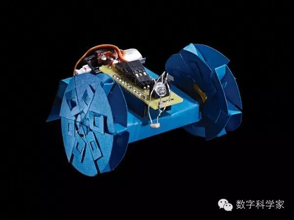
 Origami is an ancient art, but it can also become a part of modern engineering. Engineers can play with origami, such as folding space mirrors or cardiac stents. Ankur Mehta, a postdoctoral researcher at MIT, designed a robot that can be made using origami art at a low cost. Just print the blueprint and fold it according to the instructions. Of course, since it’s a robot, you also need to add an Arduino brain to control it.
Warning: Lithium polymer batteries pose a fire hazard. Please read the instructions attached to the battery before making the robot. Related statistics: Time: 5 hours Cost: $55 (approximately 357 RMB) Difficulty: Hard Tools: Printer, craft knife, ruler, soldering iron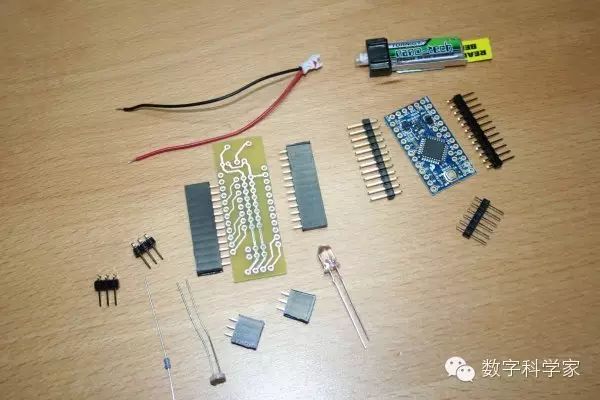 Materials: Custom daughterboard (the original purchase link is incorrect) 3 sheets of 8.5*11 inch cardstock 2 continuous rotation servos Arduino mini board 3.3V/8MHz 30 straight pins; 6 right-angle pins 30 pin headers switch battery connector 1.8k ohm resistor mini photoresistor 5mm diameter white LED FTDI Basic Breakout 3.3V Li-poly battery, voltage 3.7V, current 130mAh, capacity 25-40C Li-poly battery charger Steps: Step 1 – Daughterboard
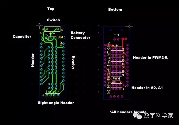 Custom daughterboard. Although the schematic diagram shows its appearance, manufacturers still need this .grb file. Step 2 – Print the robot body structure diagram
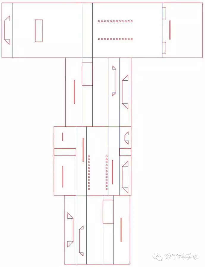
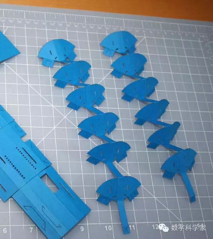
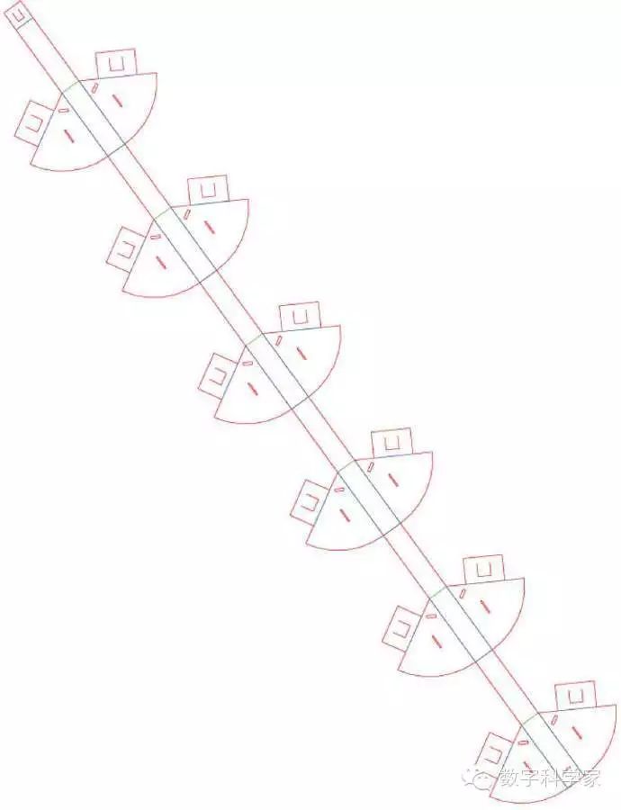 Print the templates for the robot body and wheels onto cardstock. Step 3 – Cut and fold the paper
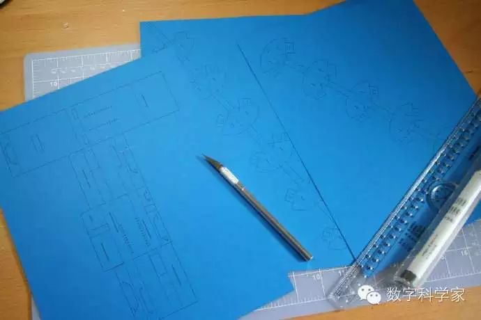 Carefully cut along the red lines with a ruler and craft knife
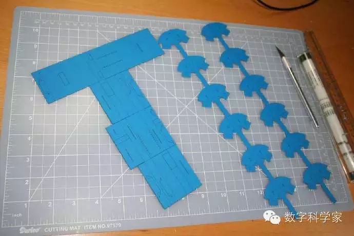 First, cut out the outer contour, then make rough folds for the details before cutting
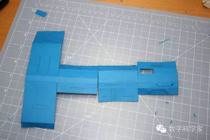 Fold along the blue and green lines; the blue line parts should be raised, and the green lines should be indented.
 After folding the blue and green lines, carefully cut the details along the red lines. Step 4 – Making the wheels
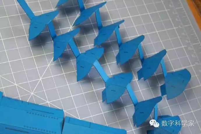 Fold the wheels
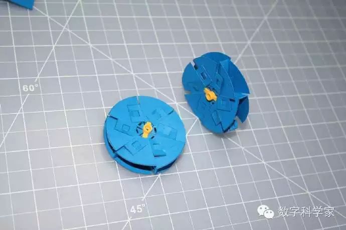 Install plastic axle pieces at the center of both wheels. Step 5 – Prepare the Arduino
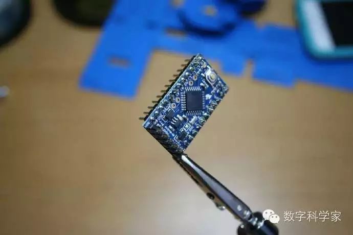 Solder 6 single pins into the reserved openings at the top of the Arduino board.
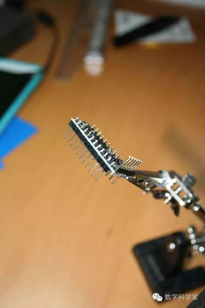 Solder 12 pins at the bottom of the board. Step 6 – Prepare the daughterboard
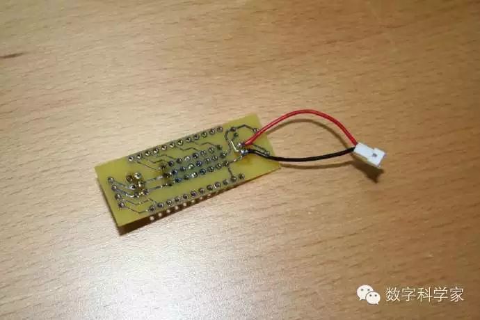 Solder the battery connection wires according to the positive and negative terminals to the top of the board.
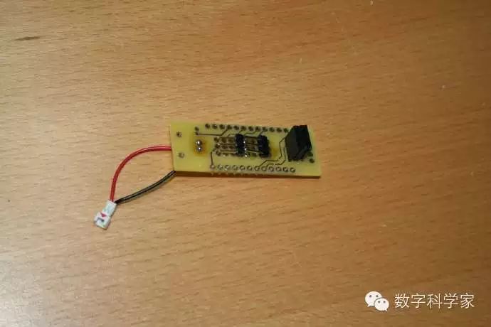 At the bottom of the daughterboard, solder 3 single pins in the 9th and 6th rows, and solder 6 pin headers at the top (this is where the LED, photoresistor, and resistor will connect).
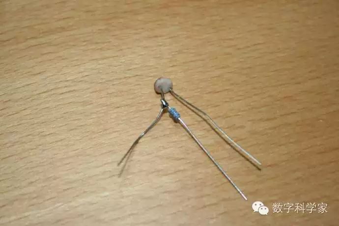 Solder one end of the resistor to the photoresistor.
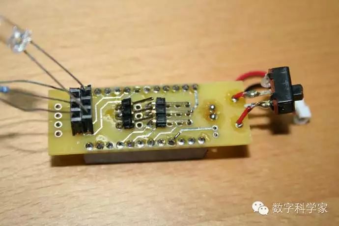 Connect the resistor and the photoresistor to the first row of three holes in the pin header, and connect the LED to two holes in the second row. Solder the switch to the bottom of the board.
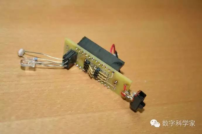 Solder 12 pin headers horizontally on both sides of the board. Step 7 – Fold the Arduino section
 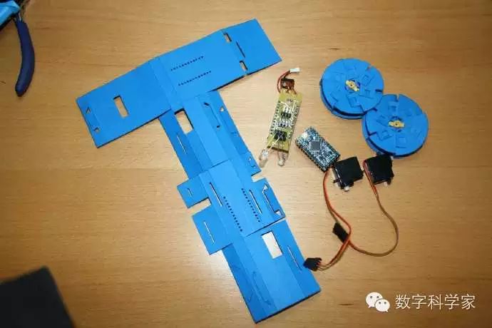 Now that the electronic components are ready, they can be folded into the paper.
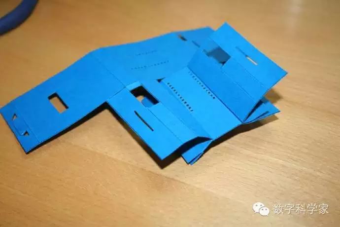
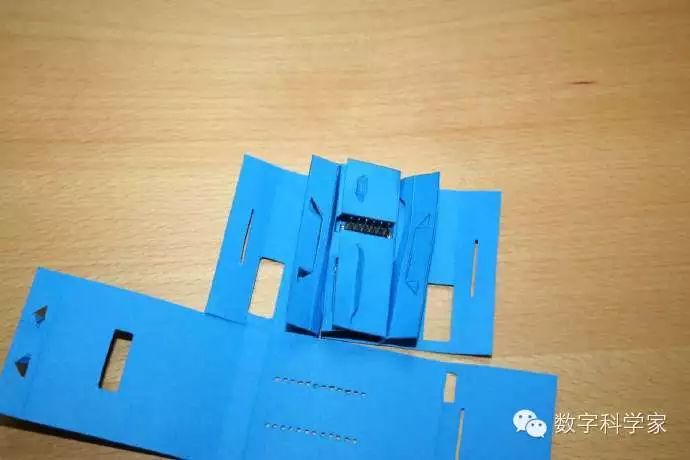 Install the Arduino on the second largest piece of paper.
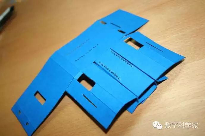 Ensure that each pin passes through the cardstock.
Insert the two smallest pieces of paper into the reserved slots for the Arduino. Insert the right-angle part of the servo system, allowing the axle to protrude through the hole in the paper.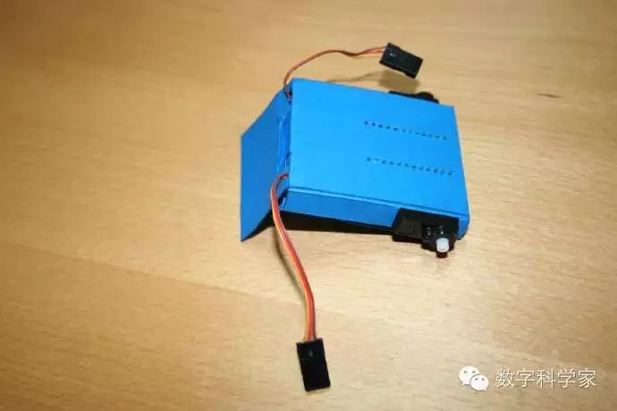 Fold and seal the remaining parts around the Arduino and servo system according to the paper structure. Step 8 – Install the wheels and daughterboard
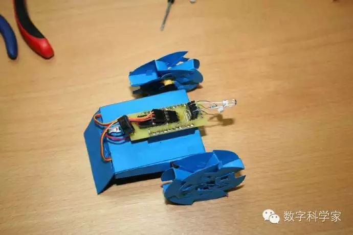
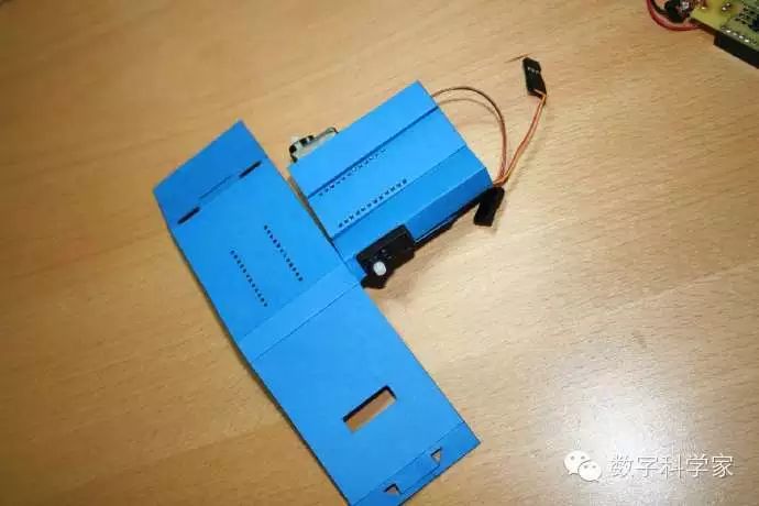
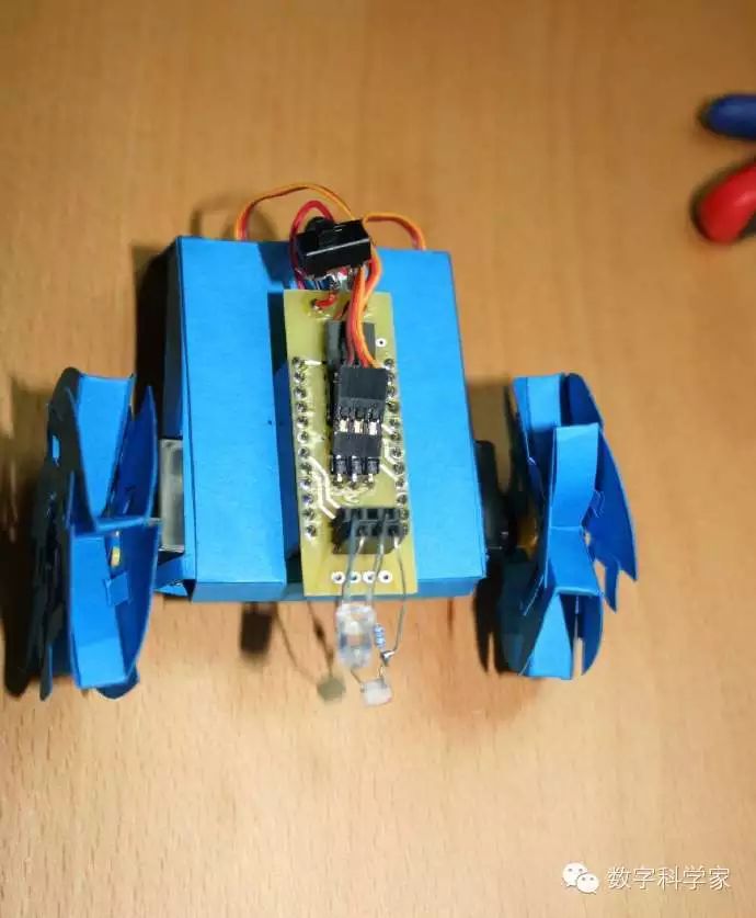 Align the wheels with the servo system and install them. Connect the pin headers of the daughterboard to the pins on the Arduino, with the switch facing the robot’s tail. Connect the servo system wires to the 9th and 6th rows. Step 9 – Coding
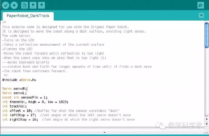 Use the FTDI Basic Breakout 3.3V to code the Arduino. This sample code is designed for the robot to move in the dark, avoiding bright areas. Step 10 – Powering
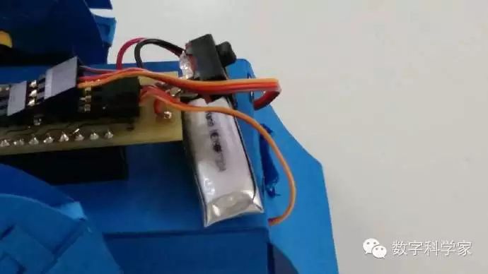 Place the battery between the daughterboard and the paper, and voila, your robot is ready to roll around!