Warm reminder: The article is approximately 3500 words long and will take about 9 minutes to read. You will definitely gain insights after reading it. Additionally, due to adjustments in the public account recommendation mechanism, remember to set it as a “starred” account to see updates from Uncommon in real-time. If you want to learn more professional and in-depth knowledge, you can join my 【Flat Panel Display Technology Learning Circle】.Welcome to join the 【Flat Panel Display Technology Learning Circle】
Recently, many readers have inquired about the cost-related information of TFT-LCD display modules. In fact, the content related to costs is quite broad, and there are many factors that influence costs, which cannot be explained in just a few words.For the same product design and material selection, the quotes provided to Manufacturer A and Manufacturer B will also show significant differences.The reasons for the price differences involve many aspects, such as: capacity utilization rate, degree of equipment automation, yield loss, strategic bundling, willingness to cooperate, etc.Of course, the factors mentioned above are not the main focus of our discussion.Uncommon is responsible for product development, so when discussing cost-related content with readers, the focus will mainly be on the factors affecting the cost of the product itself, including product design, material selection, and process technology.In previous articles, we discussed the cost influencing factors of CG glass cover plates. The article link is as follows, and readers who are particularly concerned about costs can take a look. 【Industry News】Discussing the Cost Influencing Factors of TFT-LCD Display Modules – CG Glass Cover Plate PerspectiveIn today’s article, Uncommon will take readers to understand the cost influencing factors of FPC flexible circuit boards. Due to the many factors affecting the cost of FPCA flexible circuit boards, today’s article will mainly discuss the design aspects that influence the cost of FPCA flexible circuit boards.Uncommon has identified 7 aspects from the design perspective of FPC flexible circuit boards that will affect the cost of FPCA flexible circuit boards, and the article will elaborate on these 7 aspects.Additionally, due to the length of the article, the parts related to material selection, process technology, etc., that affect the cost of FPCA flexible circuit boards will be shared with readers in future articles.01 FPCA Size and ToleranceThe size of the FPCA varies for different products. When the length and width specifications of the FPCA raw material are the same, the size of the FPCA directly affects the number of boards that can be arranged, ultimately impacting the cost of a single FPCA.Moreover, the size and tolerance of the FPCA are key control areas. Generally, the tolerance for the length and width dimensions of the FPCA is controlled at ±0.05~±0.15mm.If the tolerance control is high, such as ±0.05~0.07mm, the cutting die for the shape needs to be processed using slow wire cutting; ifthe tolerance control is average, such as ±0.1~0.15mm, then medium wire cutting can be used, which will also provide cost advantages for the FPCA.
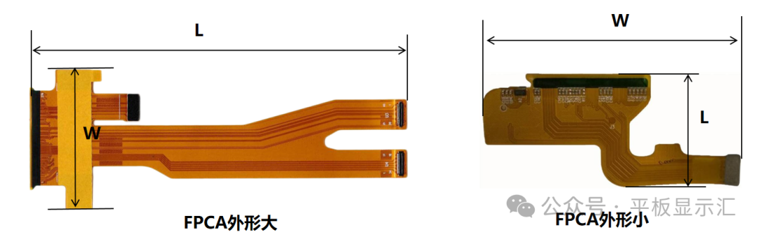 Comparison of FPCA Sizes02 FPCA Connection MethodsThe connection methods between the FPCA flexible circuit board and the main board typically include three types: snap connection, plug connection, and solder connection.Currently, in TFT-LCD display modules, snap connections and plug connectionsare predominant.The costs associated with these three types of FPCA connections differ. If we consider only the cost of the FPCA itself, the cost ranking from high to low is as follows: snap connection FPCA > plug connection FPCA > solder connection FPCA.Solder connection FPCA is used relatively less due to its lower efficiency when connecting to the main board, and the stability of the FPCA connection is poorer, with fewer repeatable connection cycles.Therefore, to reduce FPCA costs, if there are no special requirements, plug connection FPCA should be prioritized.
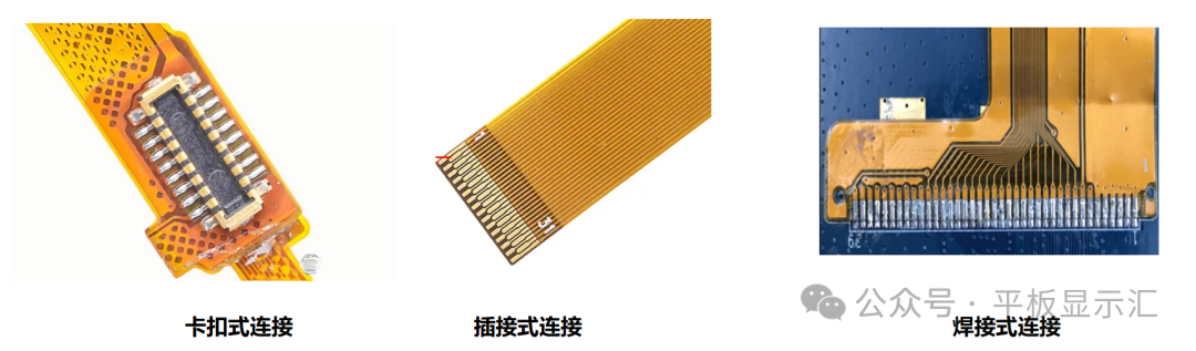 Comparison of Three FPCA Connection Methods03 FPCA Bending Area and Component Area Covering ProcessThe covering processes for the FPCA bending area and component area (component region and connector region) are typically: covering film process and thermosetting green oil process for the FPCA bending area, and covering film window opening process and photosensitive ink process for the FPCA component area.①FPCA Bending Area:As the borders of TFT-LCD display modules become narrower and the thickness of LCD panels decreases, the rebound stress requirements for the FPCA bending area are increasing. The covering film process for the FPCA bending area results in higher rebound stress compared to the thermosetting green oil process, which increases the risk of hotspots at the BLU lamp openings.The cost of using the thermosetting green oil process for the FPCA bending area is higher than that of the covering film process, as it adds an additional screen printing step for the thermosetting green oil.Generally, based on cost considerations, if the display module has a wider border and the customer has no special requirements, the covering film process should be prioritized.
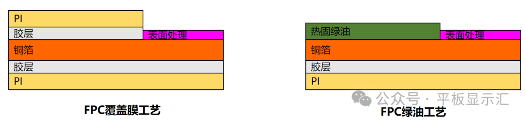 Comparison of Two Processes for FPCA Bending Area②FPCA Component Area:The FPCA component area can be divided into the component region and connector region.The mainstream covering process for the component region is the photosensitive ink covering process, mainly because smaller packaged components like 0201 and 01005 cannot meet the precision requirements for covering film window openings and SMT placement accuracy.The covering process for the connector region can be flexibly chosen according to specific project requirements, but if the covering film window opening process is used, it is essential to confirm the dimensions of the connector region: the spacing of the covering film window openings, the width of the covering film window openings, and the width of the covering film covering the PAD, to ensure they meet the process capabilities of various FPCA manufacturers.Generally, the cost of using the covering film window opening process is advantageous compared to the photosensitive ink covering process. If the design of the FPCA connector region meets the process capability requirements of the FPCA manufacturers, the covering film window opening process should be prioritized.
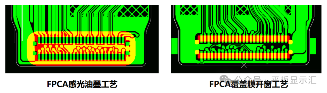 Comparison of Two Processes for FPCA Connector Region04 FPCA Steel Sheet Reinforcement Grounding RequirementsFPCA steel sheet reinforcement grounding requirements typically have two types: grounded steel sheet reinforcement and ungrounded steel sheet reinforcement.The grounding of the steel sheet reinforcement affects the cost of the FPCA.If grounding is required for the steel sheet reinforcement, the grounding impedance is usually required to be ≤5Ω; if the steel sheet reinforcement is ungrounded, there are no control requirements for its impedance.At the same time, the size of the impedance after grounding the steel sheet reinforcement also affects the cost of the FPCA to some extent. The smaller the grounding impedance requirement (<2Ω), the steel sheet needs to undergo nickel plating treatment, and the area and number of exposed copper regions in contact with the FPCA and steel sheet need to be increased to ensure that the grounding impedance meets the requirements.Generally, based on cost considerations, if the customer has no requirements for grounding the steel sheet reinforcement, it is advisable to design it as ungrounded; if the customer requires grounding but has no requirements for grounding impedance, it is recommended to control the grounding impedance at <5Ω.
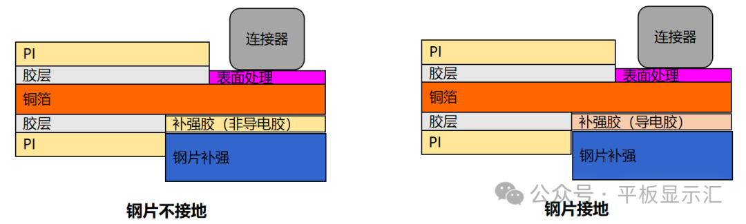 Comparison of Grounded and Ungrounded FPCA Steel Sheet Reinforcement05 FPCA Component Glue RequirementsTo avoid issues such as pad detachment and pad peeling during the bending process of FPCA components, which can affect the functionality and normal use of the TFT-LCD display module, it is usually required to apply glue in the component area to protect the component pads and enhance the strength of the pads.FPCA component glue can generally be divided into two types, also known in the industry as: full encapsulation process and semi-encapsulation process.In simple terms,the full encapsulation process means that the glue covers the entire component area, completely wrapping the components. The semi-encapsulation process means that the glue only covers the component pad area, and in principle, the glue should not touch the components unless they are small packaged components.Generally, the cost of FPCA using the full encapsulation process is higher than that of FPCA using the semi-encapsulation process. Based on cost considerations, if the customer has no special requirements, the semi-encapsulation process should be prioritized.
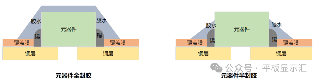 Comparison of Full and Semi Encapsulation for FPCA Components06 FPCA Exposed Copper Area and QuantityThe purpose of exposing copper on the FPCA is mainly to achieve grounding through conductive cloth and conductive copper foil, enhancing the product’s electrostatic discharge capability and improving its ESD resistance.All exposed copper areas on the FPCA require surface treatment, typically using nickel-gold plating, which involves nickel and gold deposition at the exposed copper locations.As the area and quantity of exposed copper on the FPCA increase, the consumption of gold and nickel during the nickel-gold plating process will also increase, leading to a rise in the cost of the FPCA, especially as gold prices have surged in recent years.Generally, as long as the product meets testing requirements, based on cost considerations, efforts should be made to minimize the area and quantity of exposed copper on the FPCA.
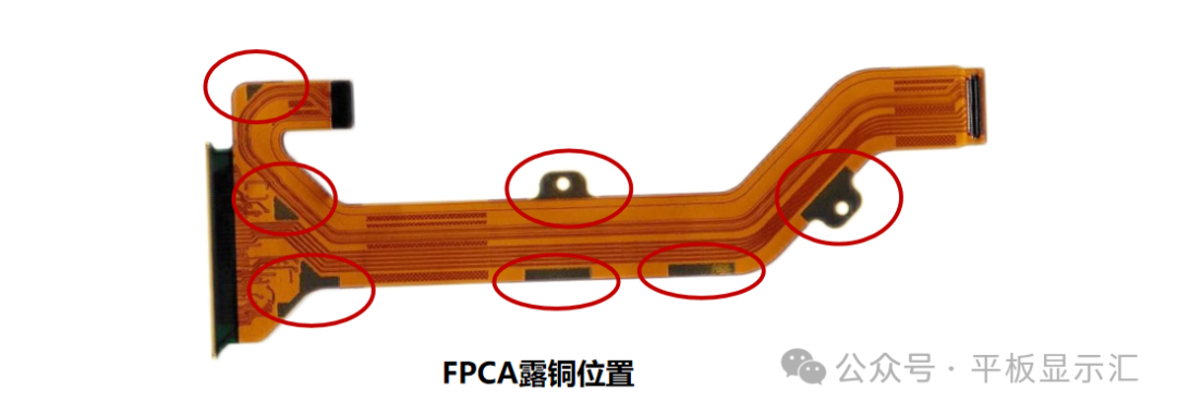 Illustration of Exposed Copper on FPCA07 FPCA EMI Electromagnetic Film Design RequirementsDuring the design process of TFT-LCD display modules, to reduce the risk of RF interference in the overall machine, it is usually required to add EMI electromagnetic film to the FPCA.The layers and area of the electromagnetic film added to the FPCA will directly affect the cost of the FPCA. For example, adding electromagnetic film to both sides of the FPCA will be more expensive than adding it to only one side; adding electromagnetic film to the entire surface of the FPCA will be more expensive than adding it only to the component area of the FPCA.Generally, based on cost considerations, it is recommended to follow these principles:① If EMI electromagnetic film can be avoided, it should be; if it must be added, prioritize adding it to one side.② Try to control the area of the added electromagnetic film; a smaller area will have cost advantages. Additionally, it is important to ensure that the added electromagnetic film is a continuous piece, avoiding segmented designs that require segmented application, which increases application costs.
 Comparison of FPCA with and without Electromagnetic FilmThere are many factors affecting the cost of FPCA from a design perspective. In this article, Uncommon has only listed some typical and common factors that influence costs. If you have more thoughts and opinions, feel free to leave comments and interact in the comment section~You can join my knowledge circle to see more comprehensive and professional content, enjoy more benefits, and communicate and progress together with Uncommon.
Alright,that’s it for today’s sharing.This is acontent-rich public account, adhering to the principle of “speak without reservation, and say everything”, follow me,and I hope it helps you.Author’s Profile:I am Uncommon, with over 10 years of experience in the display industry, having progressed from a technical novice to a technical director and product technology expert. I specialize in addressing various technical issues related to display products. I hope to help everyone avoid the pitfalls I have encountered. Follow the public account, add me as a friend, and let me help you navigate the field of flat panel display technology more smoothly. Remember to set it as astarred account, so you can see articles as soon as they are published.Scan to add Uncommon on WeChat, and note “paid article” to get any paid article document for free.
 Previous Article Recommendations:【Practical Guide】Discussing the 7 Major Influencing Factors of Adhesive Strength Between Polarizers and LCD【Technical Insights】Discussing the 6 Key Influencing Factors of Composite Optical Film DOP/POP Brightness【Technical Insights】Understanding the Mechanism of Pixel Brightness Generation in TFT-LCD and Improvement Strategies【Technical Insights】Understanding the Manufacturing Process and Key Control Projects of LED Light Sources【Technical Insights】Understanding the PET Protective Film on TFT-LCD Fully Bonded Display Modules【Practical Guide】Discussing the 6 Major Causes of Peeling Light Leakage Due to BLU Glue Iron and Improvement Strategies