The phone screen, as the face of a phone and the window for human-computer interaction, is undoubtedly important.
It’s a bit magical that it can vividly display images from life. I have always been curious; since I am curious, I decided to disassemble a screen to explore.
As I usually encounter many TFT-LCD (Thin Film Transistor Liquid Crystal Display) screens, I will disassemble a TFT-LCD MX4 screen here.
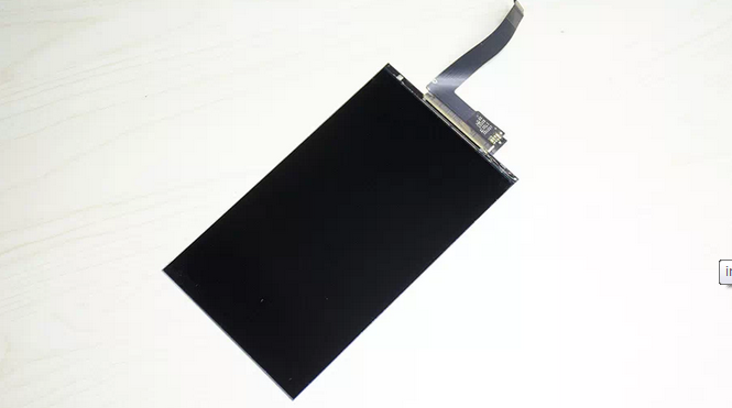
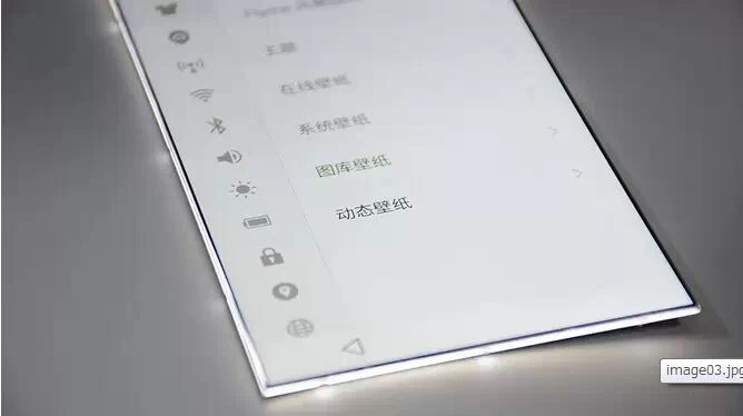
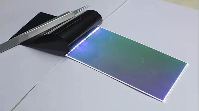
▲ 15:9 aspect ratio, resolution 1920X1152. This is a plain screen without protective glass touch.
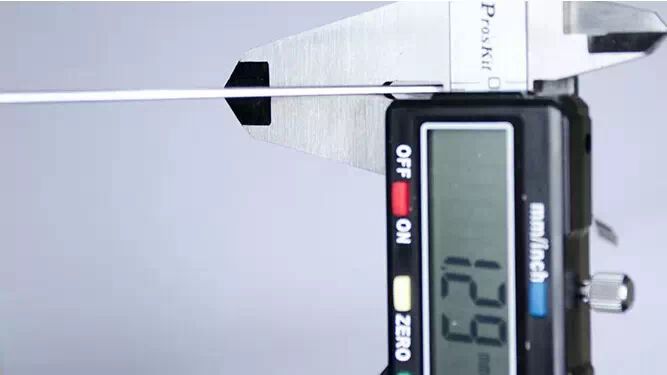
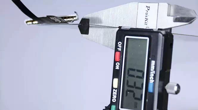
▲ Overall thickness is 1.29mm
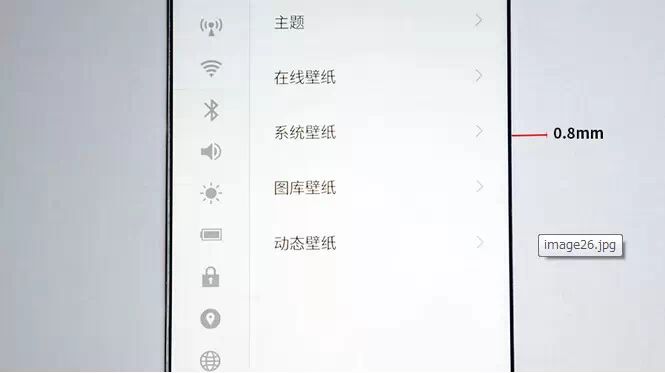
▲ The black border is only 0.8mm
When lit, there is an unprecedented sense of transparency. The 0.8mm black border is not the narrowest in the world; Sharp’s “borderless” phone has an even narrower black border of 0.6mm.
Whether a truly borderless phone can be made will be discussed at the end of the article.
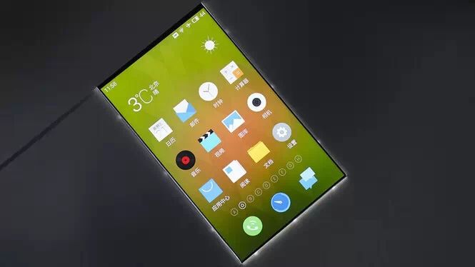
▲ So beautiful, I couldn’t help but take a few more pictures.
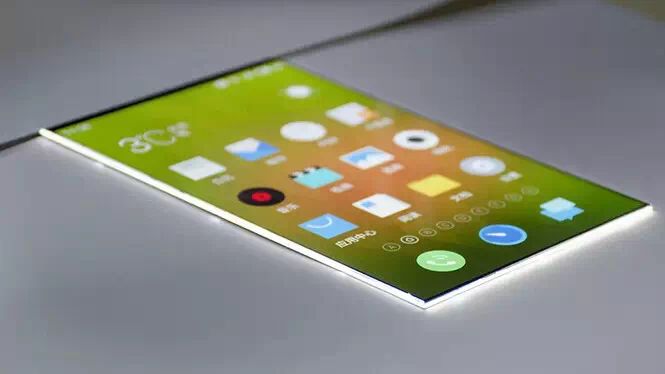
▲ Viewing angles are not a problem
▲ Transparency
The light around is from the backlight module fixed frame; light comes through the edges of the light guide plate. This phenomenon is not light leakage because it is just a plain display screen. When combined with the touch screen, there are measures to prevent light leakage.
Let’s stop the small talk and start disassembling.
▲ Light-shielding film
Black, to prevent backlight from leaking out; the one below is a reflective film.
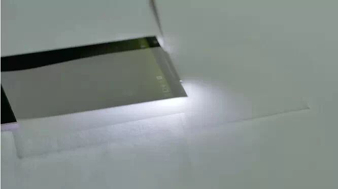
▲ Reflective film
Like a mirror, its function is to reflect light back as much as possible. As an LCD screen, maximizing the efficiency of light utilization effectively increases screen brightness.
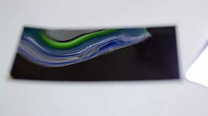
▲ Pulling out half of the reflective film, it is evident that the brightness of the lower half is significantly higher than that of the upper half.
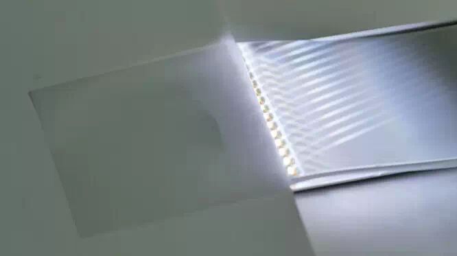
▲ Light guide plate
The function of the light guide plate is to convert the light entering from the side in a parallel direction into a non-planar direction. Thus, the parallel light hitting it becomes scattered light, traveling up and down, while the downward light is reflected back by the reflective film.
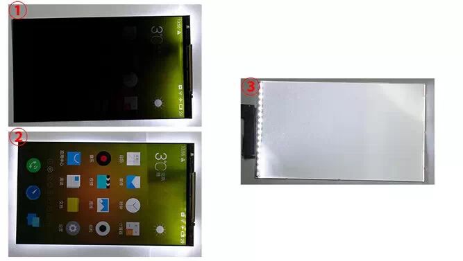
▲ Figure 1 has no light guide plate, Figure 2 has a light guide plate, Figure 3 shows the back of the light guide plate
From the pictures, we can understand the function of the light guide plate. In Figure 3, it can be seen that the light guide plate directs light in various directions toward the screen.
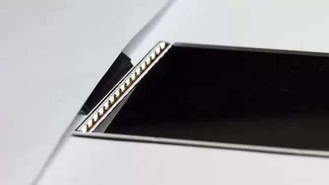
▲ LED backlight
After removing the light guide plate, the LED backlight is exposed, with 16 evenly distributed bulbs. As an LCD screen, light is its lifeblood; the brighter the LED, the brighter the screen, but this raises concerns about phone battery life. Therefore, without changing the number of LEDs, screen manufacturers improve liquid crystal technology and processes to enhance the aperture ratio to increase screen brightness. The color temperature of LED light affects the color temperature of the screen to some extent.
▲ Soft light film, as the name suggests, makes the light softer.
▲ Light enhancement film
The light emitted from the light guide plate is in random directions, and the light enhancement film reflects light that deviates too much from the vertical direction back. This is its function.
Thus, the backlight module is disassembled, and various layers are summarized in one word: light gathering.
What is the purpose of gathering so much light? That will lead to the LCD display principle that will be discussed in detail next. Friends who are not interested can skip to the end of the article.
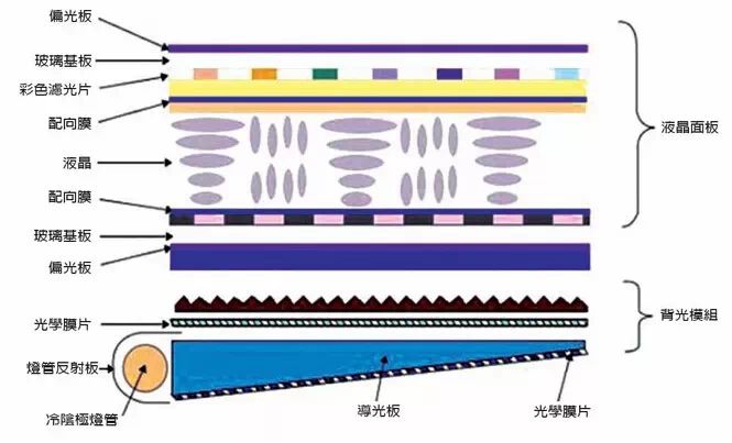
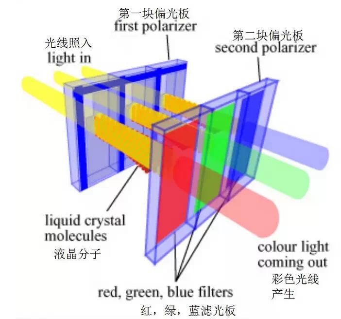
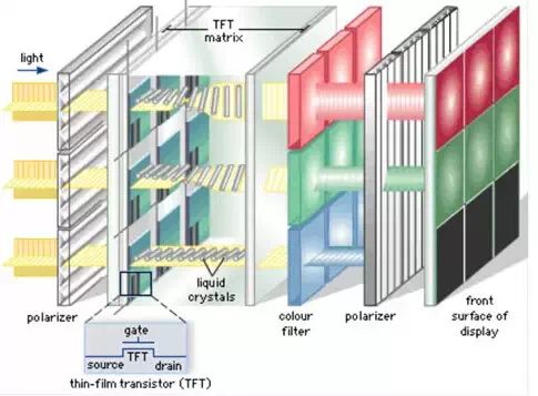
▲ Schematic diagram of TFT-LCD structure
The TFT-LCD display screen consists of two main parts: the backlight module and the liquid crystal panel. The backlight module was just disassembled above.
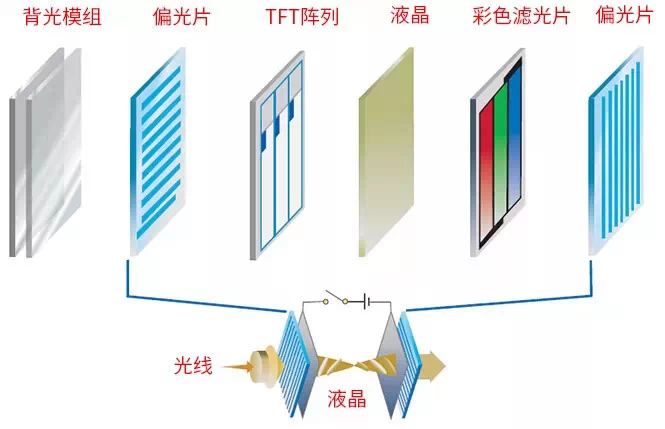
▲ Schematic diagram of display screen structure
The TFT-LCD screen is the magical journey of light. To explain simply: the light gathered by the backlight module reaches the first polarizing film, and the light waves in the vertical direction are blocked, leaving only the light in the direction parallel to the polarizing film. The light then continues to project onto the liquid crystal controlled by the TFT, where the TFT controls the orderly rotation of the liquid crystal through electric current and electric fields. The angle of rotation of the liquid crystal determines whether light can pass through the second polarizing film, thus creating a difference in light transmittance.
Since the liquid crystal itself has no color, a color filter is needed to produce various colors. A pixel consists of three basic colors: R, G, and B. By controlling the brightness of each pixel according to this principle, the desired color image can be formed.
The general principle may seem obscure, so I will use a few pictures to assist understanding.
Polarizing film
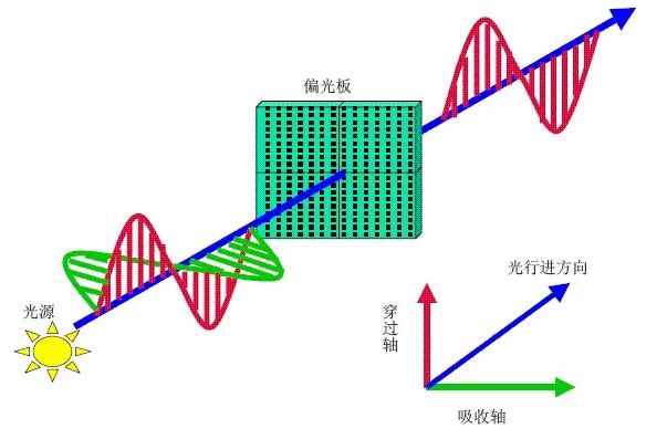
From the picture, we can see that the natural light emitted from the light source contains multiple vibration directions. After passing through the polarizing film, it becomes polarized light with only one vibration direction.
If the vibration direction of the light wave is perpendicular to the direction of the polarizing film, it will be completely blocked, resulting in the weakest light intensity, almost invisible. If it is parallel, it can pass directly, with the strongest light intensity.
Of course, if it is neither perpendicular nor parallel, the intensity of the light that passes depends on the angle between the vibration direction of the light and the direction of the polarizing film. The smaller the angle, the greater the intensity of the passing light.
The role of the liquid crystal is to change the direction of light through the TFT array after being electrified, allowing polarized light to pass through the second polarizing film, thereby seeing various intensities of light on the screen. Naturally, to display different colors of light, the corresponding color filters are used to synthesize various colors.
From the image, we can see that the liquid crystal has twisted the direction of light, allowing it to pass through the second polarizing film.
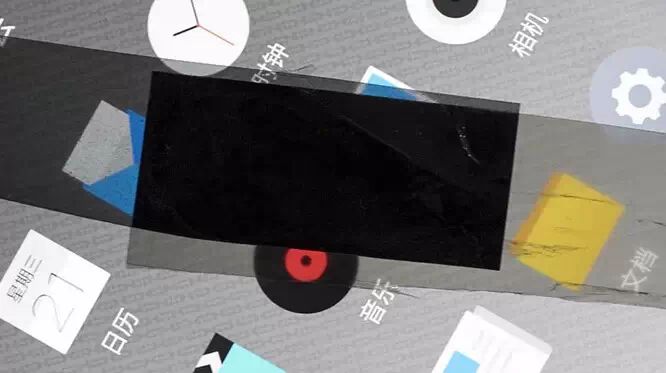
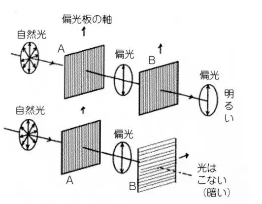
In an LCD, there are two polarizing films: one is horizontal and the other is vertical. When these two polarizing films are placed in a perpendicular arrangement, theoretically, all light is blocked, as shown in the black block in the image above.
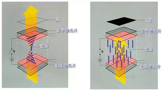
The LCD can display accurately, relying on the liquid crystal sandwiched between the two polarizing films, acting as the messenger of light.
The left image shows the power-off state, where the liquid crystal has not deflected. The light coming in from the vertical polarizing film refracts through the liquid crystal and can pass through the horizontal polarizing film, making the screen bright.
The right image, on the other hand, shows the powered-on state where the liquid crystal has deflected to a vertical state. The light hitting the liquid crystal will not be refracted, and the polarization direction of the light wave will not change, thus being blocked by the upper horizontal polarizing film, resulting in a dark display.
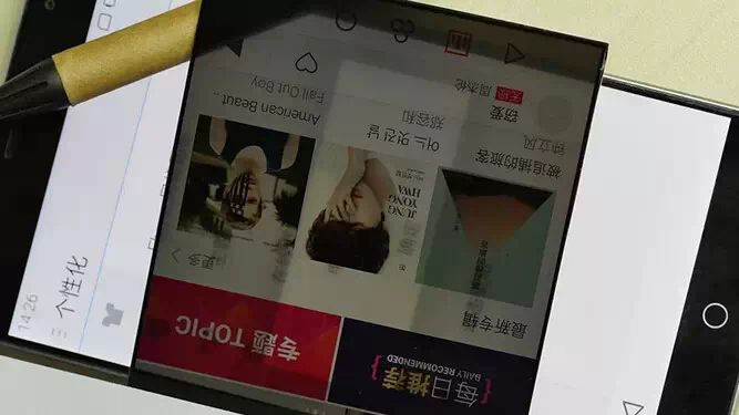
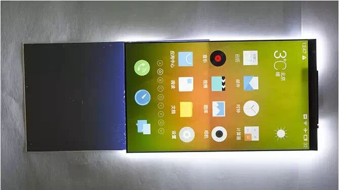
▲ LCD without the backlight module
When the backlight module is removed, the screen will still display content; it just requires light to see the displayed content, and without light, it will not work.
TFT
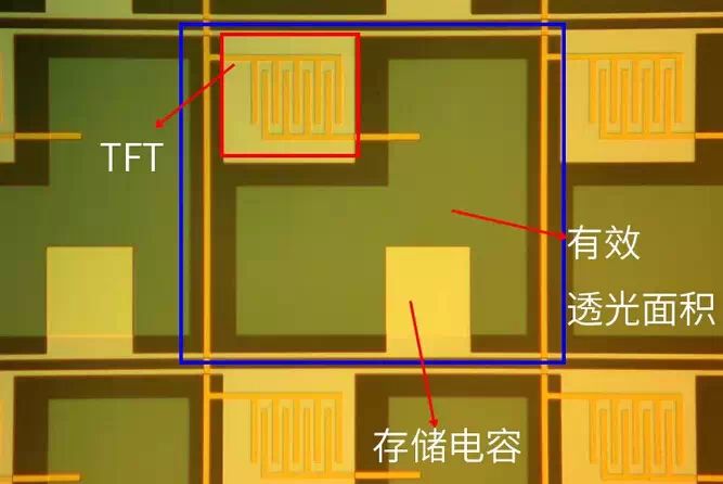
▲ Microscopic image of the TFT glass substrate
TFT stands for Thin Film Transistor, which controls and drives each independent pixel on the screen, acting as a switch to drive the liquid crystal to rotate through power on and off.
If you ask which part of the TFT-LCD display is the most difficult to make, there is no doubt that it is the TFT.
TFT, as a control circuit, is etched on the glass substrate, which requires the circuit to be well-made. The conductive line used is ITO (Indium Tin Oxide, a transparent conductive metal). ITO is transparent so that it does not block the backlight.
For example, the MX4 screen has a resolution of 1920X1152 with a size of 5.36 inches, which translates to 2,211,840 pixels. Each pixel consists of three (RGB) sub-pixels, which means 2,211,840 X 3 = 6,635,520. Each sub-pixel requires a separate TFT to control, so making such a screen requires over 6.6 million TFTs. Furthermore, calculating that in 1mm² there need to be 811 TFT units, this is just for 1080P resolution. By extrapolation, for the MX4 Pro 2K resolution, there would need to be 1,390 TFT units within 1mm². Moreover, within the TFT unit, the area occupied by the TFT line is roughly one-tenth of the TFT unit, illustrating how small the TFT is. Etching such tiny circuits on very thin glass requires extremely high craftsmanship, and there can be no interference between the TFTs.
▲ LCD display schematic
After all this, let’s review the LCD display principle.
Starting from the left, three beams of light enter from the left. The first filter blocks the vertically polarized light, leaving only the horizontally polarized light. The light passes through the glass substrate to the liquid crystal layer. The TFT switch powers the liquid crystal to rotate. The bottom beam of light does not rotate the liquid crystal, so the light continues in its original direction, passing through the color filter and being completely blocked by the second polarizing film, resulting in a black display for the corresponding sub-pixel on the front panel; the middle beam undergoes a certain angle of refraction due to rotation, but since the angle is not completely parallel to the second polarizing film, some light can pass through, but it is relatively dim; the top beam of light is completely refracted to form light parallel to the polarizing film, all passing through, resulting in the brightest red display on the front panel.
This is how the voltage strength of the TFT controls the rotation angle of the liquid crystal, leading to the brightness intensity of the light passing through, ultimately displaying different gray levels of color, forming the content displayed on the screen.
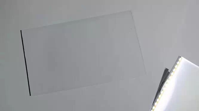
▲ Thickness of LCD dual glass
The upper colored filter glass, the lower TFT glass substrate, and the liquid crystal in between have a total thickness of 0.32mm, with the glass thickness being only 0.15mm, as thin as a cicada’s wing. You can feel it by comparing it to the thickness of an A4 sheet of paper.
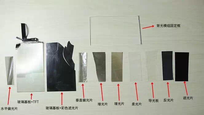
Finally, here’s a complete picture of the screen disassembly:
Lastly, let’s talk about whether borderless phones can be realized.
Borderless phones sound wonderful, but to make a borderless phone, a borderless screen must first appear. Based on current screen manufacturing technology, it is impossible to achieve a borderless screen. The borderless discussed here means no display black borders.
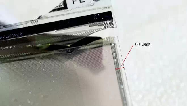
The width of the black border on both sides of the display (BM area) is known as the narrow bezel. There are also TFT electric lines on both sides; for example, for a screen with a resolution of 1920X1080, there are 1920X3=5760 sub-pixels vertically. Each row of TFTs is connected in series, requiring 5760 lines, divided by two for both sides, resulting in 2880 lines on each side. Furthermore, these lines cannot be made from ITO transparent lines on the TFT glass substrate because such dense wiring must consider circuit interference, and ITO’s anti-interference capability does not meet the requirements for such dense wiring; colored metal must be used, making this black area unavoidable.
The higher the resolution, the wider the wiring width must be. In addition to the technical limitations of wiring, the display black border also serves to prevent light leakage.
Source: Bige Technology