Abstract:
To address the challenges of high difficulty and long development cycles in wireless sensor network application development, this paper analyzes the reasons behind these issues and the current state of wireless sensor network application development technologies. Following the principles of software engineering and component design, a four-layer architecture development platform model is proposed. Based on this model, a clear architecture and rich external interfaces along with complete hardware and software components are developed for the KW01-ZigBee based wireless sensor network application development platform. This paper discusses the entire development process in detail, including the design of the development board and hardware/software components, as well as the engineering framework design. Examples of projects developed on the platform and operational tests demonstrate that the developed platform is correct, practical, and easy to use, which can reduce the technical difficulty of development and improve development efficiency.
Chinese Citation Format: Cai Bofeng, Cai Weida, Wang Yihuai. Development of KW01-ZigBee Wireless Sensor Network Application Development Platform[J]. Application of Electronic Technique, 2017, 43(3): 55-58.English Citation Format: Cai Bofeng, Cai Weida, Wang Yihuai. Design of KW01-ZigBee wireless sensor network application development platform[J]. Application of Electronic Technique, 2017, 43(3): 55-58.
0 Introduction
KW01 is the first Sub-GHz chip officially launched by Freescale in 2014, consisting of the ARM Cortex-M0+ core-based microcontroller KL26 and the SX1231-RF RF module.[1]
Wireless Sensor Networks (WSN) have penetrated various fields such as healthcare, home automation, and transportation. However, due to the complexity involved in application development, which includes network architecture and solutions, nodes, RF communication circuits, hardware and software component design, as well as the integration of communication protocols, operating systems, programming, reusability, and portability, the entry barrier is high, resulting in significant challenges, long development cycles, high costs, and poor maintainability and portability of products. To address this situation, researchers like Mao Zhengchong[2] have studied configurable embedded application design patterns, Fan Ningning[3] has researched measurement and control system frameworks, and Cao Jingyu[4] has investigated efficient software component frameworks. However, these studies focus on designing components to develop applications without creating a complete architecture for a development platform. Therefore, this paper presents a relatively general, practical, and user-friendly WSN application development platform based on KW01-ZigBee, which greatly facilitates WSN application development, reduces development difficulty, shortens development cycles, and enhances product maintainability and portability.
1 Development Platform Modeling
WSN generally consists of several terminal nodes, terminal nodes with routing functions, and multiple gateway nodes (referred to as PC nodes in this paper). The platform developed in this paper is used for the development of various nodes in WSN application projects, adopting a four-layer architecture platform model as shown in Figure 1.
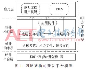
The hardware platform layer consists of the KW01-ZigBee development board, a programmer, and a USB-TTL serial cable used to connect the gateway node and PC. To reduce design costs while ensuring stable and reliable communication, all nodes in the WSN use the same development board.
The MCU side engineering framework is used for application program development, consisting of a hardware abstraction layer, a software component layer, and an application layer. The hardware abstraction layer files are primarily used for chip power-up reset and linking. The software component layer includes low-level driver components, application components, and high-level components; the user code in the application layer includes user tasks, the main program, and interrupt service routines (ISR). To facilitate the development of complex WSN application projects, the MQXLite real-time operating system (RTOS) is integrated into the framework to manage, schedule, and handle multiple tasks.[5,6]
2 Development Board and Hardware Component Design
The development board should have a clear architecture and be easy to use and maintain. Therefore, this paper designs the KW01-ZigBee development board, with the hardware structure block diagram shown in Figure 2. The KW01 MCU consists of KL26 and RF transceiver, featuring 16 KB SRAM, 128 KB Flash, and modules such as UART, SPI, IIC, TSI, ADC, and timers, characterized by high radio performance, fast transmission speed, long range, strong processing capability, and ultra-low power consumption.[7]
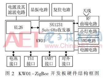
Components are the foundation and guarantee for improving system reusability and portability, and assembling systems can enhance development efficiency. During the design of the development board, each circuit module is designed as a component with clearly defined interfaces, which can greatly facilitate user usage. For instance, the minimal hardware system component consists of the minimum peripheral circuits required for program operation (such as power supply and filtering, reset, crystal oscillator, etc.); the power supply circuit component is used to convert the 5 V input to 3.3 V for chip use; the RF frontend circuit component connects the RFIO pin with the antenna.
To facilitate experiments, research, and application development, the MCU pins, except for those of the minimal hardware system, are packaged into various components, such as UART interfaces, SWD programmer interfaces, battery interfaces, and external interfaces. Figure 3 indicates the default functions of the pins, which can be used directly, while other functions can be reused according to the function reuse table provided in the KW01 technical reference manual on the NXP official website.[1]
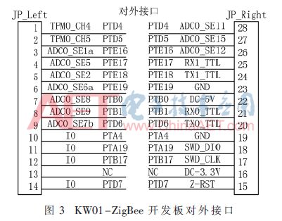
During engineering development, connecting peripheral modules to the corresponding interface components and reusing pin functions as needed can greatly improve development efficiency.
3 Low-Level Driver Component Design
The KW01 includes hardware modules such as RF, GPIO, and ADC. During programming, the corresponding hardware modules are operated through driver programs. However, the driver programs can only be reused and ported conveniently when encapsulated as low-level driver components, which also makes it easier for users to use, thereby reducing application development difficulty.
Due to space limitations, this paper will only introduce the design process of the RF driver component. According to the component design philosophy, the basic operations of initializing the RF module, receiving data, sending data, and detecting energy can be encapsulated into independent functional functions. However, to facilitate practical applications, functions for parameter initialization, CSMA/CA mechanism for sending data, and setting channel numbers should also be encapsulated. Since these all involve operations on the underlying registers of the RF hardware, they are encapsulated according to the component design principles and stored in the rf.c source file, along with rf.h for related macro definitions, underlying register mapping, and driver function prototype declarations. In component design, it is crucial to design the low-level driver function prototypes well and provide detailed comments to facilitate user usage. For example, the function for receiving RF data frames is designed to receive a frame of data from the FIFO queue and return a success or failure flag. Therefore, it needs to provide an address for the data buffer to store the received data, a pointer unit for storing the length of the received data, and a hardware filter address (i.e., the hardware address of the node in the current WSN application project, used to filter out data packets sent by other projects, with the same hardware address for all nodes in the same project). Thus, the function prototype is designed as follows:
//Function summary: Receive RF data frame
//Parameter description: plen: pointer to received data length,
//pbuf: starting address of the received data buffer, hw_adr: hardware filter address
//Function return: =0, received normally, =other values, reception abnormal
uint_8 RFReceiveFrame(uint_8* pbuf, uint_8* plen,uint_8 hw_adr);
4 MCU Side Engineering Framework Design
The MCU side engineering framework is used to provide project templates for node program development, reducing development difficulty and improving development efficiency.
4.1 Basic Principles of Engineering Framework Design
Follow the basic ideas of software engineering for reusability, portability, ease of understanding, and maintainability, laying a foundation for shortening product development cycles and improving development efficiency[8]; based on component design, enhance the reusability and portability of the framework through the design and application of various components, reducing application development difficulty[9]; organize the directory structure reasonably, classifying and categorizing according to file content to improve the maintainability of the software product.
4.2 Organizational Structure of the Engineering Framework
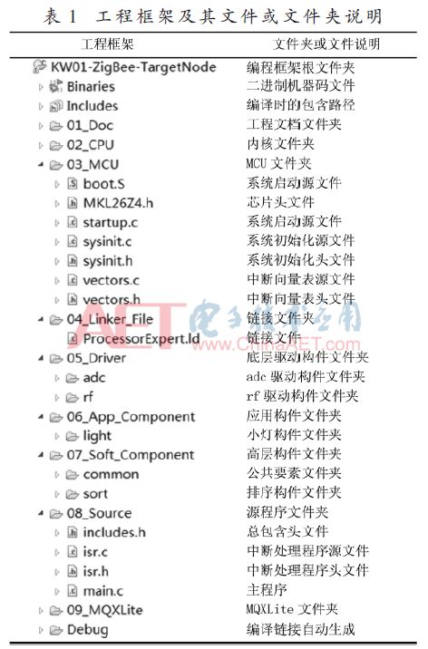
Based on the requirements of software engineering for a clear structure, reasonable file arrangement, and characteristics of portability and ease of modification, as well as the design principles mentioned above and the design philosophy of the four-layer architecture platform model in Figure 1, a tree structure for the unified MQXLite engineering framework (All-in-one MQXLite FrameWork, AMQXLFW) is constructed as shown in Table 1.
4.3 AMQXLFW Design Analysis
Except for folders unique to the development environment, the folders contained in the engineering framework are the same. Table 1 shows the 12 folders included in the Kinetis development environment (Kinetis Development Studio, KDS), with fixed quantities and names. The principles for file storage are as follows:
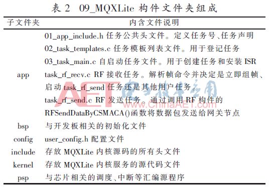
01_Doc stores project documentation, updated with project changes. 02_CPU and 03_MCU store power-on reset startup files related to the core and chip, respectively, as the core manufacturer only designs and maintains the core and source code, and does not produce chips, thus separating storage for easier porting and updates. 04_Linker_File stores the linking script for providing program code, interrupt vector tables, and storage addresses for common variables, modified with the development environment. Sufficient and complete components can effectively reduce engineering development difficulty[10]; 05_Driver, 06_App_Component, and 07_Soft_Component categorize and store low-level drivers, applications, and high-level components for easier integration, updates, and porting, with the names and contents of application and high-level components not allowed to change after encapsulation. 08_Source and 09_MQXLite are the main directories for programming and debugging without an operating system and with an operating system, respectively. In 08_Source, each file name is fixed, and content is modified with the project, while includes.h contains all component header files (using 01_app_include.h under an operating system), and isr.c includes RF receive interrupt isr_gpio_cd() and others. 09_MQXLite contains the content shown in Table 2; isr.c remains effective because the interrupt handling process is consistent with or without an operating system, but main.c is used to initialize and start MQXLite, and app is a directory added according to MQXLite task design requirements, containing three fixed files and several user task files, while other folder files are extracted from the MQX or KDS installation directory, requiring no modifications for the development board discussed in this paper.
4.4 Development Process and Advantages of Using the Framework
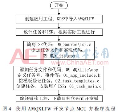
With the engineering framework, following the process shown in Figure 4 allows for convenient and rapid development of MCU-side programs. When not using the framework, kernel and chip files can be obtained from the manufacturer, and linking files can be generated by the environment, but all other files in the project need to be written manually, and the operating system needs to be ported, which results in high development difficulty, low efficiency, and long cycles. When using the framework, only a few files and codes need to be modified or added to complete the development task, and porting between different applications is also very easy.
5 Application Examples of the Development Platform
5.1 Basic Functions of Application Examples
The hardware architecture of the application example project includes terminal nodes, PC nodes, and PCs, where the PC node communicates with the PC via serial port, and terminal nodes communicate with the PC node using KW01-ZigBee development boards through RF communication. The basic function of the example is as follows: The PC sends a command data packet to collect the chip temperature, which is transmitted via serial to the PC node and then forwarded via RF to the terminal node. Upon receipt, the frame is unpacked, and the chip temperature is collected through the built-in temperature sensor of KW01, framed, and sent back to the PC node to be displayed on the PC.
5.2 MCU Side Program Development
According to the functions to be implemented by the terminal node, developing its MCU-side program requires designing one ISR and three tasks: (1) RF receive interrupt: receives data packets from the PC node and starts the RF receive task, with the data frame format defined by the user. (2) RF receive task: parses the received data packet, with the data command initiating the temperature collection task, which is included in the framework and only needs to be modified according to the task file instructions. (3) Chip temperature collection task: collects the chip temperature through the AD channel and frames it, then starts the RF send task. (4) RF send task: sends the data packet containing the chip temperature to the PC node via RF, which is then relayed to the PC. This task file is already included in the framework.
Then, in the app section, add task_temp_ad.c, and the code for temperature collection and framing is as follows:
rf_sendBuf[0]=(uint_8)’T’;//Frame header
rf_sendBuf[1]=57;//Valid frame length
rf_sendBuf[2]=(uint_8)hd_adr;//Hardware filter address
//Copy the contents of the downstream frame into the upstream frame
for(i<=3;i<=58;i++) rf_sendBuf[i]= rf_revBuf[i];
//Call KW01’s ADC component ad_read() to collect the chip’s temperature
ADResult=ad_read(26);//Collect AD value from channel 26
//Physical regression: Calculate the temperature value based on the formula in the chip manual
Vtmp=(ADResult*3300)>>16;//Voltage sampling value in mV
tmp=25-(Vtmp-706)/1.62;//Calculate temperature
//Calculate the integer and decimal parts of the temperature and encapsulate them in the last two bytes of the frame
rf_sendBuf[57]=(uint_8)tmp;
rf_sendBuf[58]=(uint_8)((tmp-(uint_8)tmp)*10+0.5);
rf_sendBuf[59]=(uint_8)’D’;//Frame tail
Other steps can be quickly completed according to the workflow in Figure 4 and the framework template for developing the terminal node MCU-side program. The development of the MCU-side program for the PC node is similar.
5.3 Application Example Operation Testing
Using VS2013 to develop the PC-side program and testing interface, the temperature collection command is issued through the interface. Upon receipt, the terminal node encapsulates the collected chip temperature in the last two bytes of the response frame’s effective data and sends it via RF to the PC side for display. Through repeated operation tests, the results are stable; when heating or cooling the chip, the test results also change accordingly. The development and testing results of the example project indicate that the development platform proposed in this paper can rapidly complete development tasks, with normal operation and scheduling of engineering tasks, stability, and real-time performance meeting engineering requirements.
6 Conclusion
This paper has developed a WSN application development platform that effectively reduces development difficulty and improves development efficiency. By designing the minimal hardware system of the MCU and various external interfaces, and hardware low-level drivers as components for user use; by providing programming framework templates and application methods, users can quickly complete application development by appropriately modifying template files and adding tasks according to specific projects. Future research will continue to strengthen the design research of interfaces, improve the component library, and optimize the engineering framework structure to enhance reusability and portability. The development method proposed in this paper serves as a valuable reference for the development of similar platforms.
References
[1] NXP. MKW01Z128 Reference Manual Rev.2[DB/OL].(2014-03-01)[2016-08-20].http://www.nxp.com/.
[2] Mao Zhengchong, Ye Zhen, Huang Fang, et al. Research on configurable embedded application design patterns based on components[J]. Computer Measurement and Control, 2015, 23(4): 1432-1434, 1437.
[3] Fan Ningning, Wang Yihuai, Chen Ruijie. Research on remote measurement and control system framework based on WSCN and E-Ethernet[J]. Modern Electronic Technology, 2016, 39(2): 53-57, 61.
[4] Cao Jingyu, Chai Weiyan, Wang Bo, et al. Research on efficient software component framework under embedded distributed computing environment[J]. Journal of Ordnance Engineering, 2013, 34(4): 451-458.
[5] NXP. MQXLite RTOS reference manual[DB/OL].(2014-09-10)[2016-08-20].http://www.nxp.com/.
[6] Chovanec M, Sarafin P. Real-time schedule for mobile robotics and WSN applications[J]. FedCSIS, 2015(5): 1199-1202.
[7] NXP. MKW01 development hardware reference manual[DB/OL].(2014-03-01)[2016-08-20].http://www.nxp.com/.
[8] Wang Yihuai, Zhu Shilang, Yao Wangshu. Embedded real-time operating system MQX application development technology[M]. Beijing: Electronics Industry Press, 2014.
[9] Qu Xinhai, Zhang Xianyu, Ding Birong. Research and implementation of controllable embedded component framework[J]. Computer Applications and Software, 2014, 31(2): 14-16, 85.
[10] Yahlali M, Chouarfia A. Towards a software component assembly evaluation[J]. IET Software, 2015, 9(1): 1-6.
Author Information:
Cai Bofeng1,2, Cai Weida3, Wang Yihuai1
(1. School of Computer Science and Technology, Soochow University, Suzhou, Jiangsu 215006; 2. School of Information Technology, Taizhou Vocational Technical College, Taizhou, Jiangsu 225300; 3. School of Aerospace, Northwestern Polytechnical University, Xi’an, Shaanxi 710072)
Recruitment Information