When I was doing software integration, I was particularly curious about what happens behind the scenes as I saw the build logs scrolling down.
So I asked Deepseek: What processes does ECU application layer software go through to compile into an executable file? The answer I received was very satisfactory. Although it contains many technical terms, it serves as a good guide for an article similar to a review.
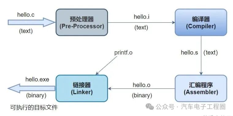
The code generated from the ECU (Electronic Control Unit) application layer Simulink model must go through a standard software compilation process to ultimately become an executable file that can run on the target microcontroller. This process is commonly referred to as the Build process, which mainly includes the following core steps: preprocessing, compilation, assembly, and linking, as shown below:
source: https://blog.csdn.net/weixin_47138646/article/details/121663547
1. Preprocessing
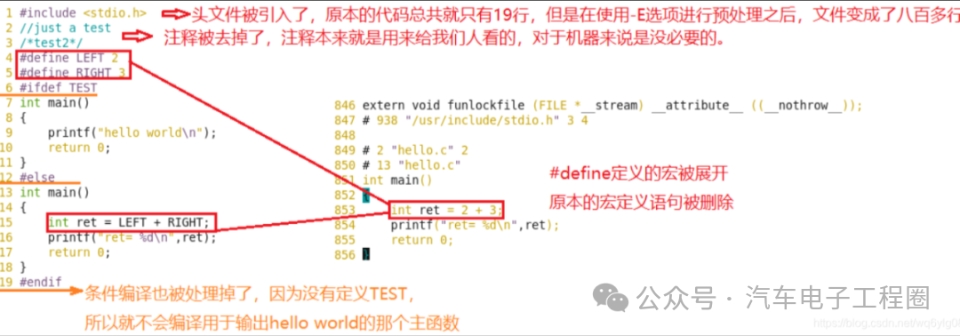
Preprocessing refers to the text-level processing and modification of source code before the compiler officially handles it. The main operations include:
-
Macro expansion, which replaces defined macros in the source code with their defined content.
-
Header file inclusion, which inserts the content of header files specified by the `#include` directive into the source file.
-
Conditional compilation, which determines which code blocks are included in subsequent compilations based on directives such as `#if`, `#ifdef`, `#ifndef`, `#else`, `#elif`, `#endif`.
-
Comment removal, which removes comments from the source code.
-
Special directive processing, which handles other preprocessor directives (such as `#pragma`, `#line`, `#error`).
source: https://blog.csdn.net/wq6ylg08/article/details/104349728
The input for preprocessing is the model-generated .c and .h source code files, and the output is the “preprocessed” source code after text replacement and modification (usually .i files, but the output is typically temporary and not visible to the user).
2. Compilation
Compilation refers to the translation of preprocessed high-level language source code (C/C++) into assembly language code for the target processor architecture. The main operations include:
-
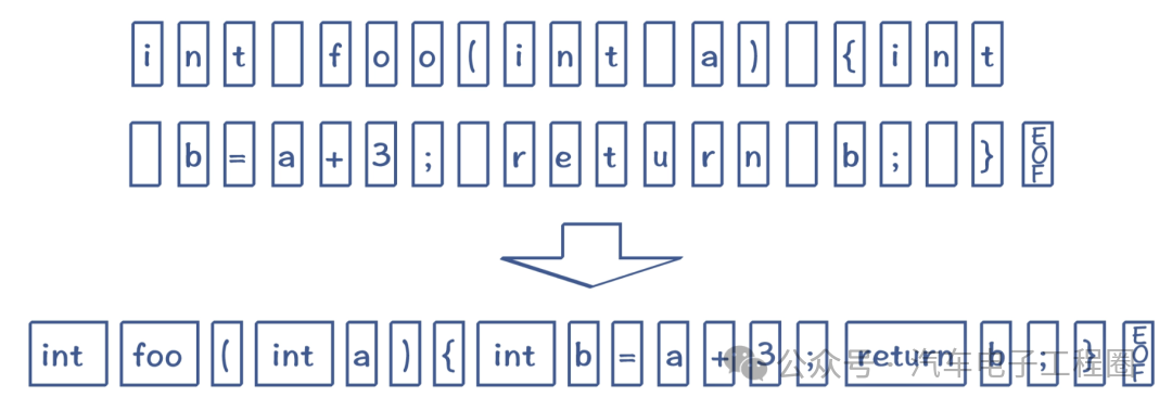
Lexical analysis, which breaks down the source code character stream into meaningful lexical units.
source:https://www.cnblogs.com/whiteBear/p/16651694.html
-
Syntactic analysis, which combines lexical units into syntactic structures (such as expressions, statements, functions, modules) according to syntax rules, constructing an abstract syntax tree.
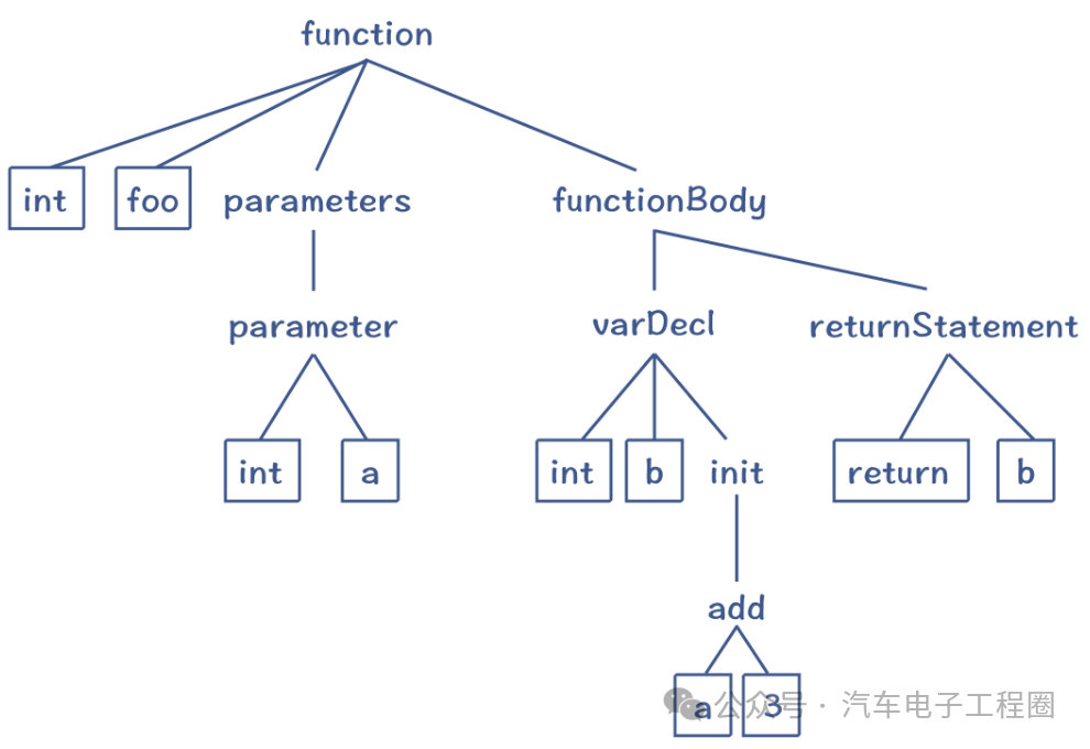
source:https://www.cnblogs.com/whiteBear/p/16651694.html
-
Semantic analysis, which checks the semantic correctness of the program (such as type checking, variable declaration checking, function call matching).
-
Intermediate code generation, which generates a machine-independent intermediate representation.
-
Code optimization, which performs various optimizations at the intermediate code level (such as constant folding, common subexpression elimination, dead code elimination, loop optimization, etc.) to improve the efficiency of the generated code (execution speed or size).
-
Target code generation, which converts the optimized intermediate code into assembly language code for a specific processor architecture.
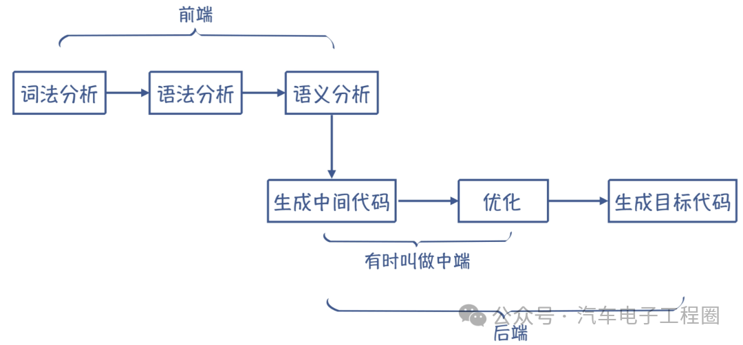
source:https://www.cnblogs.com/whiteBear/p/16651694.html
The input for compilation is the preprocessed source code. The output of compilation is the assembly language file generated for each .c file (usually .s or .asm files).
3. Assembly
Assembly refers to the translation of assembly language code into machine-readable object files. The main operations of assembly include:
-
Translating assembly instructions into corresponding machine instructions (binary opcodes) one by one.
-
Processing assembler directives (such as defining data segments, code segments, symbol labels).
-
Resolving symbol references (function names, variable names), but at this point, the addresses are usually temporary or unresolved.
-
Generating relocatable object files. This means that the code and data addresses in the file are not yet the final addresses at which they will run in memory; the linker will finalize them.
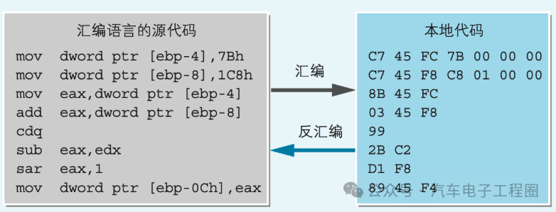
The input for assembly is the assembly language file generated by the compiler (.s/.asm). The output is the object file (usually .o or .obj files). Each .c file produces an .o file after compilation and assembly, which contains machine code, data, symbol tables (function and variable names and their attributes), and relocation information (which addresses need to be corrected during linking).
4. Linking
Linking is the process of combining multiple object files and the required library files, resolving their inter-references (function calls, variable accesses), and allocating final runtime memory addresses to generate a complete executable file.
The main operations of linking include:
-
Symbol resolution, where the linker scans all input object files and library files to build a global symbol table. For each symbol reference (such as called function names, referenced variable names), it looks up its definition (the value/address of the symbol). If a definition cannot be found, it reports an “undefined reference” error.
-
Relocation: Merging the code segments of all input object files into one code area (such as `.text`), merging the data segments of all input object files into one or more data areas (such as `.data` – initialized data, `.bss` – uninitialized data), and calculating and correcting all address references in the object files based on the final allocated memory layout (defined by the linker script). These addresses were temporary or based on 0 during the previous assembly phase.
-
Library processing: The linker extracts the required target modules from specified library files (static libraries .a/.lib or dynamically linked libraries at link time) that satisfy unresolved symbols and adds them to the linking process. The code from static libraries is copied into the final executable file; dynamic libraries only record dependencies and are loaded at runtime.
-
Generating executable file format: The linker packages the linked code, data, symbol tables, relocation information, program header information, etc., into the final executable file format (such as ELF, Intel HEX, S-Record) required by the target operating system or loader (such as `.elf`, `.hex`, `.s19`, `.bin`).
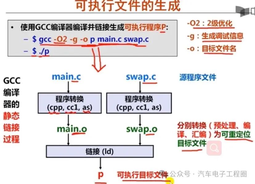
source: https://www.cnblogs.com/papering/p/10409927.html
The input for linking is all the .o/.obj files corresponding to the model-generated code; other necessary user code .o/.obj files, such as target files or libraries for low-level software (like AUTOSAR’s MCAL, CDD, service layer, etc.), target files or libraries generated by RTE (which provide interfaces between the application layer and BSW), as well as compiler runtime libraries (like `libc`, `libm` – providing standard C function implementations) and other third-party libraries.Linker scripts define the memory layout of the target processor (starting addresses and sizes of Flash/RAM), where each segment (`.text`, `.data`, `.bss`, `.rodata`, `.stack`, `.heap`, etc.) should be placed in memory. The starting address and size of the stack, and the entry point (the address where the program starts executing, usually `_start` or `Reset_Handler`).The output of linking is the executable file, such as .elf (which contains rich debugging information, symbol tables, segment information), .hex or .s19 (for Flash programming), and .map (the linking map file, which details memory allocation, the final addresses of each symbol, and the sizes and positions of each segment).
5. Summary Flowchart
The above is the overall process that ECU application layer software undergoes to compile into an executable file.

source: https://blog.csdn.net/qq_52479948/article/details/128880376
Here, there are several key points to note in ECU development:
1. Cross-compilation: The compilation process occurs on the development host, but the generated executable file runs on the specific microcontroller of the target ECU. Therefore, a cross-compilation toolchain is used.
2. Linker scripts: Crucial for embedded systems, they precisely control the layout of code and data in limited Flash and RAM resources, directly affecting program execution and performance. They need to closely match the target hardware and software architecture (such as AUTOSAR memory partitioning).
3. Low-level software integration: The model-generated code (application layer) must be correctly linked with complex low-level software (BSW, such as drivers, communication stacks, diagnostic protocol stacks, OS, RTE). This is usually achieved through code and libraries generated by AUTOSAR configuration tools.
4. Optimization: Compiler optimization options (such as `-O1`, `-O2`, `-Os`) have a significant impact on the performance (speed) and size of the generated code. On resource-constrained ECUs, code size optimization `-Os` is often very important. Optimization may also affect the debuggability of the code.
5. Debug information: Including debug information during compilation and linking (such as the `-g` option) generates an .elf file containing source code line numbers, variable names, and other information, which is crucial for source-level debugging using a debugger.
6. Post-processing: The generated executable file (such as .elf) often requires some post-processing steps before it can be used in production:
-
Converting .elf into a format more suitable for programming tools (such as .hex, .s19, .bin).
-
Checksum calculation: Calculating checksums for the entire image or specific memory areas (such as CRC), stored in a fixed location for integrity verification during ECU startup.
-
Security signing: Encrypting and signing the image to ensure the software’s source is trustworthy and its integrity (secure boot).
Therefore, the process from model-generated code to the final executable file is a rigorous process involving multiple steps such as preprocessing, compilation, assembly, and linking, requiring precise configuration of the toolchain (especially the linker script) and correct integration of all necessary software components.