The fundamental basis of data communication in today’s IP networks is the TCP/IP reference model. Today, we will use a PC to access a WEB server to deeply understand the TCP/IP reference model.
As the article is quite lengthy, it is recommended to save it for later reading.
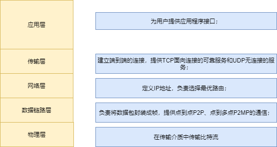
TCP/IP Reference Model
Computer Network: Simply put, a computer network is a large network formed by computers distributed around the world connected through network devices such as switches and routers using transmission media (like optical fibers) to provide data communication, resource sharing, and other services.
TCP/IP Model is the foundation of today’s IP networks, dividing the tasks of data communication into different functional layers (Layers), each with its defined functions and corresponding protocols.
For example, when a company wants to complete a business task, various departments must work together to achieve it. Each department is independent yet needs to cooperate with one another, which can be used to understand the TCP/IP reference model.
The design of the layered reference model is a very classic concept:
1) The hierarchical model design divides the communication process of the network into smaller, simpler components, thus facilitating independent development, design, and troubleshooting of each component;
2) Layers are independent yet interdependent, with each layer having its functions and defined protocol standards. Layers cooperate to complete the data communication process;
3) Through the standardization of components, it allows multiple vendors to develop;
4) By defining what functions are implemented at each layer of the model, it encourages industry standardization;
5) It allows various types of network hardware and software to communicate with each other.
Data Communication Process of PC Accessing WEB Server
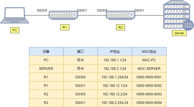
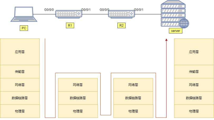
As shown in the network topology above, we will explain in detail the data communication process of a PC accessing a web server. The communication between the PC and the server goes through two routers, R1 and R2. How does the data from the PC pass through routers R1 and R2 to reach the server? (Here, we will focus on the communication process of accessing the WEB server to explain the TCP/IP reference model.) The overall macro communication process is shown in the figure below.
Next, let’s analyze it in detail (micro level):
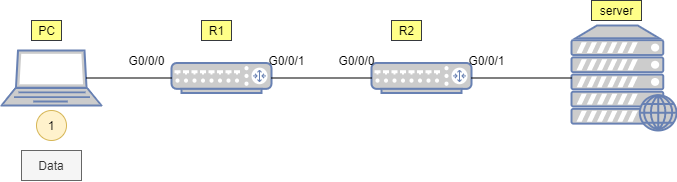
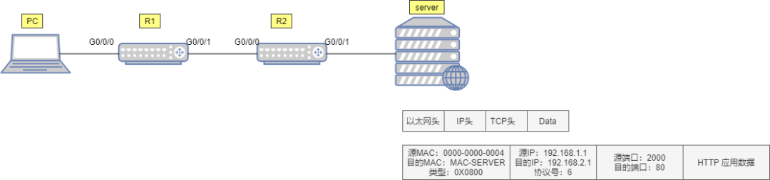
1. The end-user on the PC enters the URL in the Google browser to access the server’s WEB service. This action by the PC user triggers the HTTP application to construct application data for the user (as shown in the figure below).
This data ultimately needs to be transmitted to the server and “submitted” to the server’s HTTP application for processing. However, HTTP does not concern itself with how the data is transmitted, how addressing is done, how error checking is performed, etc. These tasks are handled by specialized layers.
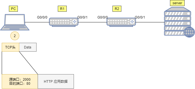
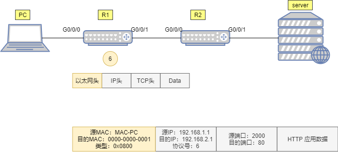
2. It is well known that the HTTP application is based on the TCP protocol, so this HTTP application data is further processed by the transport layer (Layer 4) of the TCP/IP reference model.
At this layer, the data from the upper layer HTTP application is encapsulated with a TCP header (which can be simply understood as putting it in a TCP envelope). In the TCP header, we focus on two fields (the information written on the envelope), one is the source port number, and the other is the destination port number. The source port number is a randomly generated port number (set locally on the PC, specifically for this session), and the destination port number is 80 (the default port number for HTTP services), as shown in the figure below. Then this segment is handed over to the next layer for processing.
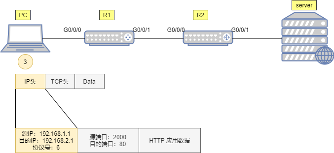
3. The next layer is the network layer (Layer 3), where the IP protocol encapsulates the data coming from the upper layer with an IP header (adding another envelope on top of the previous one, as shown in the figure below) so that this data can be forwarded (routed) by network devices from the source to the destination in the IP network.
In the IP header, we focus on three fields: source IP address, destination IP address, and protocol number.
The source address is filled with the PC’s own IP address 192.168.1.1, the destination address stores the server’s IP address 192.168.2.1, and the protocol number field stores the value 6, which is a well-known value, meaning that the upper layer protocol type is TCP, indicating that the upper layer protocol encapsulated after this IP header is TCP (a vivid description is that the protocol field indicates that the IP envelope contains TCP content). Once done, this data is handed over to the next layer for processing.
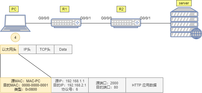
4. To allow this IP packet to be transmitted over the link (from one node of the link to another), a data link layer (Layer 2) header must also be added to the packet so that the data can be successfully transmitted over the link to the other end.
Since the link between the PC and R1 is Ethernet, the incoming IP packet is encapsulated with an Ethernet frame header (adding another envelope).
The source MAC address written in this frame header is the MAC of the PC’s network card. But what about the destination MAC?
The PC knows that the destination of the data is the IP address 192.168.2.1, while its own IP is 192.168.1.1/24. Clearly, the destination is not in the same IP segment as itself, so it needs to consult its default gateway to help forward the packet.
First, the data must be forwarded to the gateway, right? Therefore, the destination MAC address is filled with the MAC address corresponding to the gateway 192.168.1.254. However, initially, the PC may not know the MAC address corresponding to 192.168.1.254, so it will send an ARP broadcast to request the MAC of 192.168.1.254. The GE0/0/0 port of R1 will receive this ARP request and respond with an ARP response message. This way, the PC knows the MAC of the gateway, and it fills the gateway MAC 0018-0011-0001 in the destination MAC address field of the Ethernet frame header.
Additionally, the type field of the Ethernet frame header is filled with the value 0x0800, indicating that the data frame header encapsulates an IP packet. After much effort, this data frame (Frame) is finally completed, as shown in the figure below:
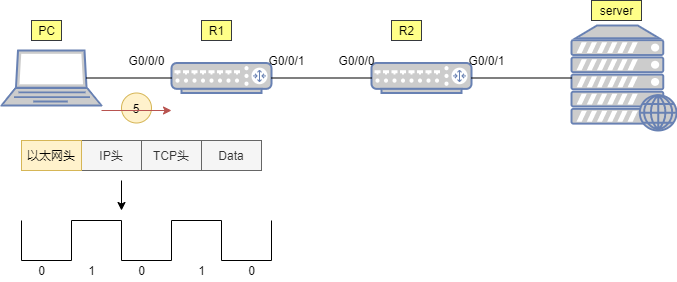
5. In fact, what is transmitted over the physical link is a stream of bits (bit flow), and ultimately this Ethernet data frame is converted into a series of 10101001 and transmitted through the transmission medium to router R1, as shown in the figure below:
6. Upon receiving a string of bit streams 01010, R1 first restores them into a data frame (as shown in the figure below).
Then it checks whether the data frame has been damaged during transmission. If not, it parses the destination MAC address in the data frame header to confirm whether the destination MAC address is its own interface GE0/0/0 MAC. If it is, it receives and continues processing; if not, it discards it.
Here, we can see that the destination MAC is the MAC of interface GE0/0/0, so it continues to check the type field of the data frame header and finds it is 0x0800, thus knowing that it contains an IP packet. It then strips the Ethernet frame header or unencapsulates it and hands over the data inside to the upper layer IP protocol for further processing.
7. Next, R1’s IP protocol stack continues to process this packet. It first checks whether the data in the IP packet has been damaged during transmission. If not, it checks the destination IP address in the IP header (as shown in the figure below).
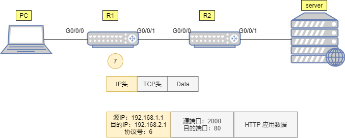
It finds that the destination IP address is 192.168.2.1, which is not its own IP address—this data packet is meant for someone else. It then starts to look up the routing table with the destination address 192.168.2.1 to see if there is a route to this destination. It finds one, and this routing entry indicates that it should send the data packet out through the GE0/0/1 port and hand it over to the next hop IP address 192.168.12.2.
Thus, it no longer continues to unpack the IP header to see what is inside but hands the IP packet back to the data link layer for processing.
8. Next, R1’s data link layer continues to process the IP packet from the upper layer. It encapsulates this IP packet with a new Ethernet frame header, where the source MAC address is the MAC of R1’s GE0/0/1 port: 0000-0000-0002, and the destination MAC is the MAC corresponding to the next hop router 192.168.12.2.
Of course, initially, R1 does not know this MAC, so another round of ARP request broadcast and response process occurs, and it finally obtains this MAC: 0000-0000-0003. It then fills this value in the destination MAC field. After completing the new data frame encapsulation (as shown in the figure below), R1 converts this data frame into 1010101… and transmits it to R2 through electrical signals.

9. R2 receives these bit streams 10101… and first restores them into frames. It then checks the frame header and finds that the destination MAC is its own interface MAC, and the type field in the frame header is 0x0800 (indicating that the upper layer protocol is IP, meaning that the data frame header encapsulates an IP packet). It then strips the data frame header and hands over the IP data packet to the IP protocol for processing.
10. During the processing of the IP protocol, it finds that the destination IP address is not the IP of this router (as shown in the figure below). Thus, it knows that this data packet is not sent to itself. It looks up the destination IP address 192.168.2.1 in its routing table and finds that R2’s GE0/0/1 port is connected to the 192.168.2.0/24 network. It then hands this IP packet back to the lower layer protocol for processing.
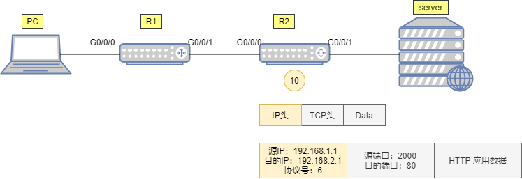
11. R2 continues to process by encapsulating a new data frame header for this IP packet. In the header, the source MAC is R2’s GE0/0/1 port MAC, and the destination MAC is the MAC corresponding to the IP address 192.168.2.1. If the ARP table has the MAC corresponding to 192.168.2.1, it directly writes the MAC address into the destination MAC. If not, it sends an ARP request message to request that address. The type field is still filled with 0x0800. Finally, R2 sends this data frame to the server, as shown in the figure below:
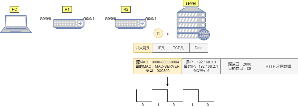
12. Finally, the data frame reaches the server (as shown in the figure below). The server first restores these bit streams into frames and checks to see if the frame is damaged. If not, it checks the destination MAC of the data frame and finds that it is indeed its own network card MAC. It then checks the type field and finds it is 0x0800, knowing that it contains an IP packet. It strips the frame header and hands the inner IP data packet over to the IP protocol for processing.
The IP protocol layer receives this data packet and first checks whether the IP packet is damaged. If not, it checks the destination IP address and finds that the destination IP address is 192.168.2.1—exactly the IP of its own network card. Thus, it knows that this IP packet is sent to itself. It then continues to check the protocol field in the IP packet header and finds that the protocol field is filled with the value 6, indicating that the IP packet header encapsulates TCP data. It then strips the IP packet header and hands the TCP data inside to the upper layer TCP protocol for processing.
When TCP processes this data, it checks the destination port number in the TCP header and finds that the destination port number is 80, while the server’s local TCP port 80 is open and available for the HTTP application. Therefore, it strips the TCP header and hands the payload to the HTTP application. Finally, the HTTP application data sent from the PC reaches its destination—the HTTP application on the server.
—END—
Further Reading:
-
107.5 billion! Huawei is out! ZTE and OPPO are the winners
-
Is Huawei going to sell its business again? Insiders respond!
-
Honor may be added to the blacklist! Is it useless to separate from Huawei?
-
How can Huawei live with dignity and quality? 320.4 billion!
-
Nokia loses three hundred billion orders, Huawei successfully counterattacks
-
Breaking news, Harmony OS welcomes its first phone outside Huawei!
-
Yu Chengdong is fighting hard! Officially announces new plans, Huawei’s situation is becoming clearer
Master 5G content in just 2 minutes every day! Long press the QR code below to follow

 Submissions | Cooperation | Consultation
Contact Email: [email protected]