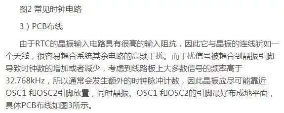
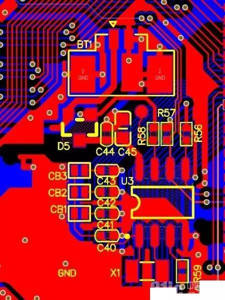
Figure 3 PCB Wiring
4) Circuit Related Explanation
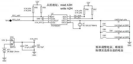
As shown in Figure 1, R56 and R57 are the pull-up resistors on the I2C bus. The interrupt output and clock output of the PCF8563 are both open-drain outputs, so external pull-up resistors are also needed, such as R58 and R59 in Figure 1. If these two signals are not used, the corresponding pull-up resistors can be omitted.
For the PCF8563 chip, an external clock crystal of 32.768kHz (like X1 in Figure 1) is required. It is recommended to use a crystal with ±20ppm or better stability. The typical application circuit for the PCF8563 recommends using a 15pF matching capacitor for the crystal, which can be adjusted accordingly in practical applications to achieve higher precision for the RTC clock source. Generally, the matching capacitor for the crystal can be adjusted between 15pF and 21pF (relative to the ±20ppm precision 32.768kHz crystal). A 15pF capacitor results in a slightly high clock frequency, whereas a 21pF capacitor results in a slightly low clock frequency.
5) Precision Adjustment Method
1. Set the PCF8563 clock output to active (CLKOUT) with an output frequency of 32.768kHz;
2. Use a high-precision frequency counter to measure the frequency of the CLKOUT output;
3. Based on the measured frequency, adjust CB1, CB2, and CB3 by shorting or disconnecting them. If the frequency is higher than 32.768kHz, increase the capacitor value; if lower, decrease the capacitor value.
Note: The values of C41, C42, and C43 in Figure 1 should be between 1pF and 3pF, and the combination method should be determined based on the actual situation for quick adjustments. Recommended combinations are (3pF, 3pF, 3pF), (1pF, 2pF, 3pF), or (2pF, 3pF, 4pF).
3. Low Power Design for RTC
Many RTCs are designed to operate solely on a battery. When the main power is off, a small lithium battery can drive the oscillator and the entire clock circuit. How can the power consumption of the RTC circuit be reduced during operation?
Several methods can be applied to reduce RTC power consumption:
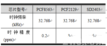
Select low-power RTCs, such as the PCF8563. Table 2 shows a comparison of power consumption for different RTCs.
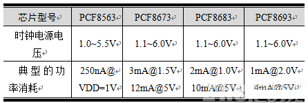
Table 2 Comparison of Power Consumption for Common RTCs
In the RTC power switching circuit, choose a diode with low leakage current, such as BAV74. When the system power supply voltage of 3.3V is disconnected, the lithium battery CR2032 (3V/225mAh) powers the RTC through the diode;
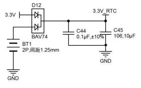
Figure 4 RTC Power Switching Circuit
Minimize and rationalize access to the RTC to reduce dynamic current on the I2C bus;
Design the pull-up resistors on the I2C bus to be as large as possible, for example, 10k;
In application, turn off the RTC’s clock CLKOUT output by setting the register.


To facilitate better learning, Changxue Electronics has specially added a public account for microcontrollers and EDA, pushing relevant knowledge daily. I hope it helps your studies!