Design of a Clothes Drying Window Control System Based on NodeMCU
Authors: Wang Bin a, Zhang Yu a, Gao Shufen a , Qu Binwen a , Hu Xie b,c (Jianghan University a. Engineering Training Center; b. School of Artificial Intelligence; c. Institute of Artificial Intelligence, Wuhan, Hubei 430056)
Abstract
With the rapid development of Internet of Things technology, smart home systems have begun to emerge and rapidly spread, leading to an increasing number of smart home devices with networking capabilities. This paper designs and develops a clothes drying window control system based on smartphone network control. The system is based on the ESP8266 platform, utilizing WiFi networking technology to connect to a cloud server, enabling remote control via mobile phone and voice control. This NodeMCU has built-in hardware conditions to interface with sensors, allowing for remote app and voice assistant control, and automatically opening the window for drying clothes based on weather conditions.
Keywords
Clothes drying window; control system; WiFi; MCU
0 Introduction
The clothes drying window is a device that integrates a window and a drying rack, coordinating both to meet indoor ventilation and clothing drying needs simultaneously. Currently, domestic manufacturers of smart drying equipment typically separate the drying device from the window, and they are all installed inside the balcony. Based on different situations, they can vertically rise and fall, controlled by a circuit to achieve drying functionality. To meet the needs of fully drying clothes and ensuring indoor air circulation when no one is at home, this paper designs a linkage-type intelligent retractable clothes drying window system that combines the window and drying rack. This system is designed according to the actual mechanical structure, integrating sensors and controlling through an Internet of Things (IoT) platform to implement this smart home control solution.
1 Overall System Design Structure
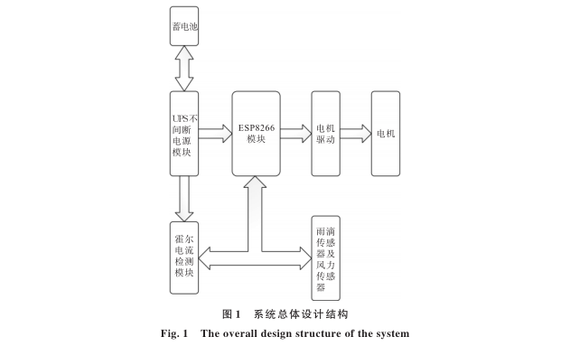
The system consists of a microcontroller NodeMCU core board, Hall sensor, 24 V battery, uninterruptible power supply (UPS) module, DM542 motor driver, 24 V DC stepper motor, and a 24 V to 5 V power supply module. The overall structure of the system is shown in Figure 1. Among them, the operating voltage and current of the battery are 24 V and 3 A, respectively; the role of the UPS module is to achieve seamless switching between normal power supply and battery power supply, while providing charging protection for the battery, preventing overcharging that could damage the battery, ensuring stable circuit operation [1-2]; the Hall current detection module is WCS1800, with a current detection range of -25 ~ +25 A, outputting TTL level signals, and this module detects power outages and returns signals to the microcontroller; both the raindrop and wind speed sensors operate at 3.3 V and output logical levels, sending signals to the microcontroller to inform the program of current rain or wind conditions. The motor driver module uses DM542, which operates at a voltage of 20 ~ 50 V for stepper motor driving, connecting the microcontroller and power supply, ensuring that the microcontroller’s WeChat account can indirectly control the motor; the motor operates at 24 V with a current of 3 A, receiving driving signals from the motor driver to operate, ultimately controlling the mechanical structure to achieve the corresponding functionality. The ESP8266 module is the NodeMCU Lua V3 IoT development board CH340G, with 16 logic ports and 1 analog port, serving as the control core of the entire circuit, connecting all modules and responsible for communication, signal processing, and ensuring all automatic controls function normally [3-4].
2 System Hardware Design
2.1 Main Control Design
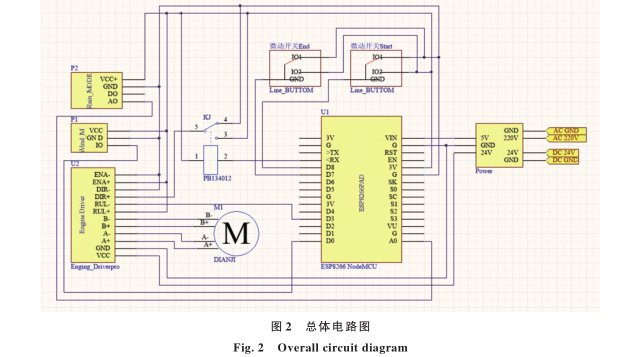
The main control part is the core of the entire system device, primarily connecting to the wireless network and accessing the server, also serving as the control center connecting peripheral sensors, receiving control commands sent from the mobile phone to the cloud, and interfacing with the circuit to control the motor’s operation [5]. The main control system uses the ESP8266 module, with I/O interfaces including one A0 analog port and all available input-output logic ports. Among them, the A0 analog port receives the analog voltage value from the wind speed sensor, and the MCU calculates its wind speed. The logic port D0 receives the logical value from the raindrop sensor to determine if it is raining, while D1, D2, and D5 connect to micro switches to obtain the specific position of the window, and D3, D6, D7, D8, D9 (RX) are used to control the motor driver to achieve motor operation. The overall circuit diagram is shown in Figure 2.
2.2 Sensors
Sensors are the core of the entire circuit that enables automatic control. The MCU perceives external changes through collected sensor signals and makes corresponding adjustments. The sensors used in this paper are two types: raindrop sensor and wind speed sensor.
Raindrop sensor: This is realized through a sensing plate and signal conversion module. When no raindrop falls on the sensing plate, the resistance of the sensing plate is set to infinity, and the signal conversion module outputs a high logical level; when raindrops fall on the sensing plate, the resistance of the sensing plate changes, and once the resistance is too low, the signal conversion module outputs a low logical level, sending the output logical signal through the D0 port to the MCU for processing.
Wind speed sensor: Composed of a generator and blades, it rotates the blades driven by wind to drive the motor. At this time, the motor generates an analog voltage, which is processed by a voltage detection module that reduces the voltage generated by the motor to 1/5. Since the maximum voltage that the MCU’s A0 port can receive is 3.3 V, while the maximum voltage that the sensor can generate is 5 V, the purpose of the voltage detection module is to prevent excessive voltage from damaging the MCU.
Hall current sensor: When current passes through a conductor perpendicular to a magnetic field, a potential difference is generated across the ends of the conductor, allowing for signal detection. Its functions are: ① After amplification, it outputs a corresponding analog signal suitable for A/D conversion; ② Outputs a switch signal, where, based on a preset current value, when the actual current exceeds the preset limit, the switch signal changes from low to high. This paper uses function ②, transmitting the high and low levels outputted by this module to the main control module to detect power outages [6-7].
2.3 Motor Driver Circuit
The motor driver circuit is the core of controlling the motor’s operation by the main control module. This paper uses the DM542 stepper motor driver, where the microcontroller simulates a PWM pulse sent to the driver’s PUL through its logic I/O ports, adjusting the PWM duty cycle to change the motor’s operating speed, and triggering the high and low levels to pull up the driver’s PUL enable via controlling I/O outputs, thereby starting the motor operation. Similarly, the microcontroller changes the motor’s rotation direction by controlling the opto-isolator relay that triggers the motor driver DIR.
2.4 UPS Uninterruptible Circuit and Power Supply Module Design
The core of the UPS uninterruptible circuit design is the UPS module, which has a power of 60 W and operates at 24 V. Its core functions are: ① When the circuit operates normally with household power input, the power supply outputs one set of 24 V for the entire circuit to operate normally, and another set outputs 24 V for battery charging; ② Stops automatically when the battery is full; ③ When a power outage occurs, the module automatically switches to battery output to maintain emergency power supply for the entire circuit, achieving seamless switching without any power interruption during the switching process. In addition, the Hall current sensor measures the current of the 220 V household electricity to determine the current status of the main control MCU. When the MCU receives the power outage message, it sends a notification message to the user’s mobile WeChat through the server, indicating that there is a power outage at home. At this time, the system’s power supply mode is backup power supply, allowing the user to remotely control the system to change the default emergency operation.
3 Software System Design
3.1 Main Program Design
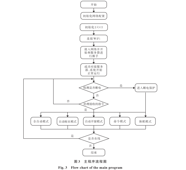
The main program part is primarily responsible for reasonable resource scheduling for all functions, allocating priorities and handling task interruptions, playing a crucial role in the entire system. This program is based on the overall underlying control logic rules, planning the switching and scheduling among various mode modules and conflict response times, optimizing program response times and related data uploads and refreshes. By initializing each module, controlling I/O outputs, and executing received cloud instructions, the program achieves normal operation of the entire system [8]. The program flowchart is shown in Figure 3.
3.2 Local Control Center and Sensor Program Design
The local control center program encapsulates the driving functions of each module into different functions, implementing the interface between the docking program and hardware. Its role is twofold: on one hand, it receives relevant data from local sensors, and on the other hand, the local control center function is responsible for the basic rules of operation for each hardware component and provides an interface for the main program to call, ensuring orderly execution when the main function calls local data. The main programs include the rainwater sensing collection program and the wind speed collection program.
Rainwater sensing collection program: It determines whether it is currently raining based on the high and low levels processed by the rainwater sensing module and returns a boolean value to the main program.
Wind speed collection program: When the MCU collects the sampling value Value from the A0 port, it converts the sampling value into the actual voltage V (mV) using formula (1):

Since the ESP8266 ADC pin has a 10-bit resolution, the sampling value obtained from the A0 port ranges from 0 to 1023. The range of 0 to 1023 belongs to the sampling value of the bare chip inside the ESP8266 development board, while the ESP8266 development boards used in this paper are equipped with internal voltage dividers to increase the input range to 0 to 3.3 V. Therefore, as shown in formula (1), since the voltage conversion module reduces the voltage to 1/5 of its original value, the collected Value from A0 is first divided by 1024, then multiplied by 3300, and finally multiplied by 5 to obtain the final actual voltage value.
After obtaining the voltage, this paper only needs to convert the voltage into wind speed through the motor’s curve relationship, as shown in formula (2):
 In this formula, F represents wind speed in m/s. The wind speed detection program ultimately determines the wind speed based on these relationships and returns the corresponding value.
3.3 Network Control Center and Voice Control Program Design
The network control center serves as the connection bridge for the entire system, using the cloud server as an intermediary. The network control center is responsible for uploading local data to the cloud, then sending it to the mobile app for the user. The user receives the relevant data and can control the app to send related commands to the MCU via the cloud server, which are then processed by the main program for rule determination, ultimately calling local functions to complete the entire operation process.
Voice control is also part of network control, achieved by docking with third-party voice assistant platforms, allowing data to interface with the server. The data sent from the platform connects to the network control center for voice control. Thus, a bidirectional interaction process from local to cloud and from cloud back to local constitutes the entire system’s operational framework [9-11].
The network connection part interfaces with the server through the message queuing telemetry transport (MQTT) protocol; MQTT is a “lightweight” communication protocol based on a publish/subscribe model, built on the TCP/IP protocol and released by IBM in 1999. The greatest advantage of MQTT is that it can provide real-time reliable messaging services for connecting remote devices with minimal code and limited bandwidth [12]. As a low-overhead, low-bandwidth communication protocol, it has widespread applications in IoT, small devices, and mobile applications.
When the program starts, the ESP8266 first connects to the WiFi to obtain an IP address, then interfaces with the server through the MQTT protocol for handshake. The function sends a key to the server to interface with the corresponding configuration, and upon successful configuration, the program sends the first data packet to the control app, which returns the reception status, indicating that the program has successfully started [13].
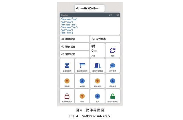
3.4 Software Control Client Interface Design
The software control client is designed based on the Blinker platform, utilizing the components provided by the platform and accessing its cloud server interface to achieve data exchange and connection between the app and MCU, controlling the operation of the entire system. The interface displays various modes, window switches, and clothing drying status in real time, providing various control modes for user interaction. The control interface is shown in Figure 4.
4 Conclusion
This paper designs a clothes drying window control system based on smartphone network control. The software system has been put into practical use, showing good results and stable operation, capable of conveniently meeting people’s needs for controlling windows and drying clothes. It is cost-effective and user-friendly. Currently, there are still areas for improvement in this project, such as modularizing the circuit design, which would simplify circuit maintenance and make fault detection easier; the program could also integrate more voice platforms like Tmall Genie to provide users with convenient services. Future research will gradually improve this system for application in various scenarios.
References omitted
Funding Project: Jianghan University Doctoral Start-up Fund (1008-06620001); Hubei Provincial College Students’ Innovation and Entrepreneurship Training Program
Source: Wang Bin, Zhang Yu, Gao Shufen, et al. Design of a Clothes Drying Window Control System Based on NodeMCU [J]. Journal of Jianghan University (Natural Science Edition), 2021, 49(4): 60-65.
DOI: 10.16389/j.cnki.cn42-1737/n.2021.04.008