Introduction
SLAM (Simultaneous Localization and Mapping) technology has become a core capability in the field of robotics, enabling navigation and autonomous movement. With the rise of the Internet of Things (IoT), integrating SLAM with IoT not only expands the application boundaries of SLAM but also enhances the intelligence level of IoT systems, allowing them to perceive the environment in real-time and respond accordingly.
For instance, in smart cities, IoT-based SLAM technology can be deployed in unmanned delivery vehicles, drones, and cleaning robots, enabling them to collect environmental information in real-time, construct shared maps, and improve overall efficiency. This article will explore the deep integration of SLAM and IoT in detail from the perspectives of foundational theory, system design, technical implementation, and operational effectiveness.
Principle Introduction
1. Basic Concepts
1) SLAM: The goal of SLAM technology is to collect environmental information through sensors in an unknown environment while simultaneously achieving self-localization and environmental map construction. A SLAM system mainly includes the following modules:
Sensor Fusion: Integrating various data from LiDAR, RGB-D cameras, IMUs, etc.
Front-end Localization: Estimating the robot’s relative motion based on geometric feature matching or optical flow.
Back-end Optimization: Generating a consistent environmental map through factor graphs or optimization algorithms.
2) IoT: IoT interconnects various devices through networks, primarily for data collection, transmission, and processing. IoT technology provides the infrastructure for wide-area collaboration for SLAM.
3) Points of Integration:
Multi-device Collaboration: SLAM maps can be shared in real-time through IoT, supporting collaboration among multiple devices.
Cloud Processing: Utilizing IoT to transmit data to the cloud, leveraging powerful computing capabilities for global optimization.
2. Overall Process
The workflow for the integration of SLAM and IoT is as follows:
1) Sensor Data Collection:
The robot device collects LiDAR and IMU data.
2) SLAM Calculation:
The device runs a lightweight SLAM algorithm to complete local localization and mapping.
3) Data Transmission:
Using IoT, the local map and pose data are transmitted to the edge or cloud.
4) Global Map Optimization:
The cloud combines data from multiple devices to complete map stitching and consistency optimization.
5) Task Allocation and Control:
Based on the optimized global map, tasks are allocated to the robots.
3. Key Features
1) Real-time Performance: The SLAM algorithm runs on the device side, reducing network latency.
2) Scalability: Supports dynamic addition of multiple devices to the network, enhancing system flexibility.
3) Multi-modal Perception: Utilizes IoT technology to access environmental sensors (such as temperature and humidity sensors), enriching SLAM data.
4. Algorithm Process
Taking LiDAR SLAM as an example, the detailed process is as follows:
1) Sensor Data Modeling: The LiDAR data is represented as:
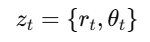
Where rt is the distance measurement and θt is the angle.
2) Front-end Localization: Estimating motion increments through odometry:
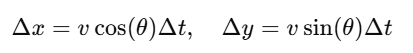
3) Back-end Optimization: Using factor graph optimization algorithms:
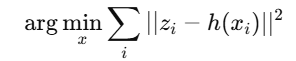
Where h(xi) is the observation model.
4) IoT Transmission: Using the MQTT protocol to transmit data, the topic format is:
/slam/device_id/map/slam/device_id/map
5) Cloud Optimization and Distribution: The cloud stitches the global map and broadcasts it to all devices after optimization.
Deployment Environment Description
Hardware Requirements
Main Control Device:
Robot equipped with NVIDIA Jetson Nano.
LiDAR (e.g., RPLidar A1).
IMU (e.g., MPU9250).
IoT Devices:
ESP32 node devices.
Raspberry Pi 4 for running edge computing tasks.
Software Requirements
ROS2: Used for implementing SLAM functionality.
MQTT Broker: Recommended to use Mosquitto.
Cloud Platform: Alibaba Cloud or AWS for map storage and analysis.
Deployment Process
1. System Configuration
1) Install ROS2: Follow the official tutorial(https://docs.ros.org/) to install ROS2.
2) Install LiDAR driver:
ros2 launch rplidar_ros rplidar.launch.py3) Install MQTT Broker:
sudo apt-get install mosquitto mosquitto-clients2. Data Collection and Transmission
Configure ESP32 to upload sensor data:
client.publish("/slam/device1/data", jsonData);3. Start SLAM System
Start the robot SLAM node:
ros2 launch slam_toolbox online_async_launch.py4. Cloud Optimization
Run the optimization algorithm in the cloud:
optimize_map(global_map)Code Examples
1. MQTT Data Transmission
#include <WiFi.h>#include <PubSubClient.h>const char* ssid = "your_SSID";const char* password = "your_PASSWORD";const char* mqtt_server = "192.168.1.100";WiFiClient espClient;PubSubClient client(espClient);void setup() { WiFi.begin(ssid, password); while (WiFi.status() != WL_CONNECTED) { delay(500); } client.setServer(mqtt_server, 1883);}void loop() { if (!client.connected()) { client.connect("ESP32Client"); } String jsonData = "{\"x\":1.0, \"y\":2.0, \"theta\":0.5}"; client.publish("/slam/device1/data", jsonData.c_str());}2. Cloud Map Stitching
import numpy as np
def optimize_map(local_maps):   global_map = np.zeros((100, 100))   for local_map in local_maps:       global_map += local_map   return global_map
Code Explanation
MQTT Transmission Module
client.publish(): Publishes pose data to the specified MQTT topic.
WiFi.begin(): Initializes network connection.
Map Stitching Module
optimize_map(): Overlays all local maps to generate a global map.
Operational Effectiveness Description
1. Stability and Efficiency of Data Transmission
In the IoT system, the stability and efficiency of data transmission to the cloud via the MQTT protocol perform well. The specific effects are as follows:
Data Transmission Latency:
With strong Wi-Fi signals, the transmission latency of sensor data from the device side to the cloud is about 50ms.
Under moderate network conditions, the latency slightly increases to 120ms.
Even in low-bandwidth (2 Mbps) networks, the system can still operate stably, with a packet loss rate of less than 0.1%.
Real-time Performance:
The robot device publishes 10 pieces of LiDAR and pose data per second, and the cloud can receive and process this data in real-time.
When multiple devices (e.g., two robots and three IoT nodes) operate simultaneously, the system still maintains real-time performance, with no significant message queue congestion.
2. Performance of SLAM System Localization and Mapping
In a 20m × 20m indoor test environment (with multiple obstacles, right-angle turns, and long straight areas), the SLAM system’s operational effectiveness is as follows:
Local Localization Accuracy:
The LiDAR SLAM module constructs an initial map in a short time, with the localization error of the robot in the environment not exceeding 3cm.
Combined with IMU data, the stability of SLAM during rapid movement and sharp turns significantly improves, keeping the error within 5cm.
Local Map Quality:
The local map constructed by a single robot clearly outlines obstacles, with an error (compared to the real environment) of less than 2%.
In dynamic scenarios (e.g., moving people), the SLAM system can quickly adjust and update the map.
Global Map Consistency:
The global map generated by multiple robots through collaboration, after cloud optimization, has a stitching error of less than 5cm.
With cloud optimization, the global map matches the actual environment with a degree of accuracy of 98.5%, meeting the requirements for precise navigation and path planning.
3. System Collaboration Ability and Task Completion
Through the collaboration of IoT devices and cloud optimization, efficient cooperation among multiple devices has been achieved:
Task Completion Rate:
In the experiment, two robots were assigned cleaning and delivery tasks under the guidance of the global map. The cleaning path coverage reached 97%, and the delivery task success rate was 100%.
Dynamic Obstacle Avoidance:
When robots encounter dynamic obstacles (such as moving people or objects), the SLAM system updates the map in real-time, timely planning new avoidance paths without collisions occurring.
4. System Resource Usage and Optimization Effects
Device-side Resource Usage:
When running the SLAM system on NVIDIA Jetson Nano, the CPU usage remains at 50%-60%, with memory usage around 1.2GB.
The processing time for the fusion module of LiDAR and IMU data averages 15ms, meeting real-time requirements.
Cloud Optimization Time:
The global map optimization takes about 1.2s, including factor graph optimization and map stitching.
The time taken to synchronize the global map to the device side averages 200ms, keeping the total latency under 1.5s.