|
Click Jiangsu Laser Industry Technology Innovation Strategic Alliance Follow/ Top WeChat Official Account |
|
News | Technical Article | Conference Forum | Processing Services |
Introduction to Jiangsu Laser Alliance:
Display technology is ubiquitous in our daily lives; its wide applications cover smartphones, tablets, desktop monitors, televisions, data projectors, and augmented reality/virtual reality devices. Currently, Liquid Crystal Displays (LCDs) and Organic Light Emitting Diodes (OLEDs) are the two main flat panel display technologies. Recently, mini-LEDs (mLEDs) and micro-LEDs (μLEDs) have emerged, significantly enhancing the dynamic range of LCDs or serving as sunlight-readable emissive displays. However, challenges such as mass transfer yield and defect repair still exist, undoubtedly impacting costs. “Which technology has won: LCD, OLED, or micro-LEDs (μLED)?” has become a hot topic of debate.
Liquid Crystal Displays (LCDs) were invented in the late 1960s and early 1970s. Since the 2000s, LCDs have gradually replaced bulky Cathode Ray Tubes (CRTs) and have become the dominant technology. However, LCDs are non-transmissive and require a Backlight Unit (BLU), which not only increases panel thickness but also limits their flexibility and form factor. Meanwhile, after 30 years of equipment development and massive investments in advanced manufacturing technology, Organic Light Emitting Diode (OLED) displays have rapidly developed, making foldable smartphones and rollable televisions possible. In recent years, emissive OLED displays have gained momentum and have fiercely competed with LCDs in televisions and smartphones due to their outstanding unprecedented dark states, thin profiles, and free shapes. However, certain key issues, such as aging and lifespan, still need improvement. Recently, micro-LEDs (μLEDs) and mini-LEDs (mLEDs) have become the next generation of displays. Micro-LEDs (μLEDs) are particularly attractive for transparent displays and high-brightness displays, while mini-LEDs (mLEDs) can serve as local dimming backlights for high dynamic range (HDR) LCDs or as emissive displays. Both mLEDs and μLEDs offer ultra-high brightness and long lifespans. These features are highly desired for sunlight-readable displays such as smartphones, public information displays, and vehicle displays.
To compare different displays, the following are important performance metrics: (1) HDR and high ambient contrast, (2) high resolution or high pixel density for virtual reality to minimize the screen door effect, (3) wide color gamut, (4) wide viewing angles with negligible color shift, (5) fast motion picture response time (MPRT) to suppress image blur during rapid motion, (6) low power consumption, which is particularly important for battery-powered mobile displays, (7) thin, free-form, and lightweight systems, and (8) low cost.
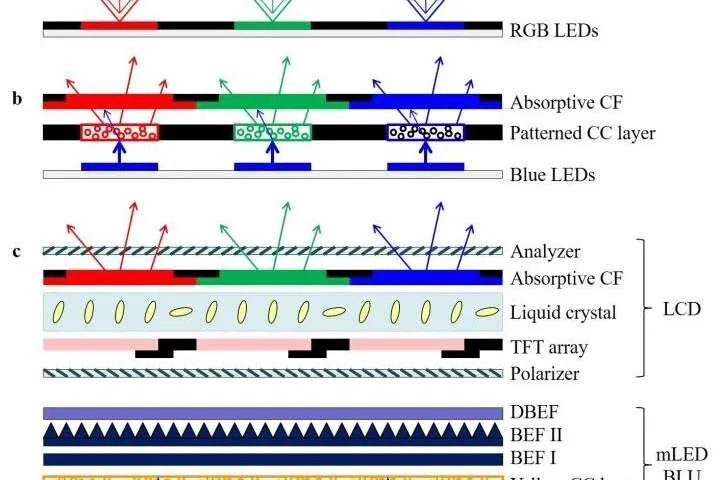
Figure 1 shows three commonly used device configurations: red, green, blue (RGB) chip emissive displays (Figure 1a), color conversion (CC) emissive displays (Figure 1b), and mLED-backlit LCD (Figure 1c). In emissive displays (Figure 1a, b), mLED /μLED/ OLED chips serve as subpixels. In non-emissive LCDs (Figure 1c), the mLED backlight is divided into a regional structure. Each region contains several mLED chips to control panel brightness, and each region can be selectively turned on and off. The liquid crystal panel consists of M and N pixels, with each RGB subpixel independently addressed by a Thin Film Transistor (TFT) to adjust the brightness transmittance of the backlight. The three types of full-color image generation methods differ.
Power Consumption
The power consumption of mLED /μLED/ OLED displays mainly depends on the design of the driving circuit, LED quantum efficiency, and optical system efficiency. Several methods can improve the power efficiency of mLED /μLED/ OLED displays. For lower Pwire, we can divide the panel into more units and use low resistivity conductive material.
1. Reducing PTFT Driver Transistors
PTFT can be optimized by TD parameters. Higher Cox and larger WT/LT help reduce VDS_min and PTFT transistors. Among them,
WT and LT are circuit design parameters but should be adjusted within reasonable limits. μT and Cox are thin film transistor process parameters. The oxide layer at the gate of the thin film transistor is designed to be thin enough to achieve high Cox and good insulation. High μT can be obtained from complementary metal-oxide-semiconductor transistors. Therefore, industry leaders have begun to replace thin film transistors with complementary metal-oxide-semiconductor driver integrated circuits. However, the resolution and size of powder metallurgy displays are limited. Thus, to achieve high resolution and large size displays, multiple permanent magnets need to be tiled. The main challenges of tiled designs are the visibility and uniformity of seams, which require small emission apertures and post-manufacturing calibration. In the AM (amplitude modulation) scheme, each pixel has a unit circuit, which usually requires compensation design. This scheme has high spatial requirements and is particularly unfriendly to high ppi displays. Highly integrated integrated circuits alleviate this issue and provide more precise current control. Additionally, this technology enables miniaturized pulse width modulation drive circuits. In 2015, Lumiode reported a method of integrating silicon thin film transistors into AM μLED microdisplays without transfer. In 2017, X-Celeprint demonstrated AM μLED displays with pixelated micro-scale ICs through micro-transfer printing. In 2018, JDC launched a 2000 ppi μLED on a silicon substrate. In 2019, LETI proposed wafer-level manufacturing of basic pixel units and transferring them to receiving substrates. The main disadvantage of integrated circuit drivers is that their costs are higher than those of thin film transistors. With the increase in the number of integrated circuits used, the panel costs also rise. Therefore, using integrated circuits in low-resolution color displays is more cost-effective than in high-resolution emissive displays.
2. Reducing PLED through High EQEchip/VF Operation
From Eq, researchers found that ηLED is proportional to EQEchip/VF operation preference.
Contrast Ratio and ACR
The CR (Contrast Ratio) of emissive displays is inherently high. In non-radiative LCDs, its CR is limited by depolarization effects, primarily influenced by the LC materials used, surface orientation, and CFs. In practical applications, ambient light reflected (from the outer surface or from internal electrodes) can be perceived in addition to the displayed content.
Response Time and MPRT
The response time of mLED /μLED/ OLED chips is several orders of magnitude faster than that of LC.
However, it cannot be concluded that mLED /μLED/ OLED emissive displays provide a smoother visual experience than LCDs.
HDR
HDR refers to display standards designed to faithfully reproduce natural scenes. Currently, multiple HDR formats coexist, such as basic HDR10, excellent Dolby Vision, broadcast-friendly Hybrid Log Gamma (HLG), and the emerging Advanced HDR. HDR displays may support one or more HDR formats, but hardware specifications are more crucial to final performance than the formats employed.
Future Application Scenarios
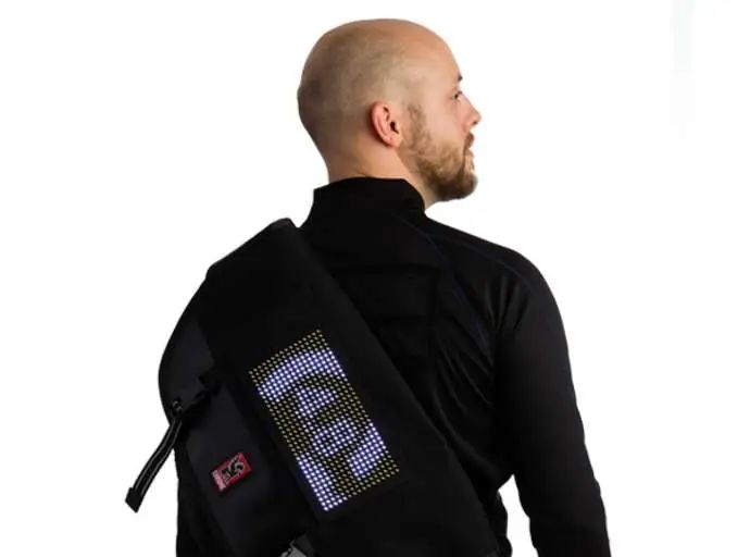
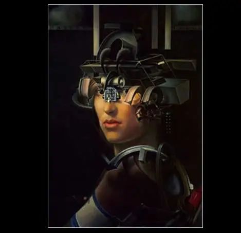
1. Wearable Displays
Wearable electronics, such as virtual reality/augmented reality headsets and smart wristbands, are considered the next generation of information platforms. Common requirements for wearable displays include low power consumption, lightweight, and high resolution density. Specifically, near-eye displays for virtual reality/augmented reality require a fast MPRT to reduce motion image blur, while smart wristbands prefer flexibility.
2. Vehicle Displays
Typical vehicle displays for cars and spacecraft include central dashboards and heads-up display (HUD) units. For these applications, reliability and sunlight readability are crucial for driver safety. A wider operating temperature range is another requirement for vehicle displays. Inorganic LEDs have the widest temperature range. OLED displays perform well in cold environments but age quickly if heated. LCDs react slowly in cold weather, with their upper limit depending on the cleaning temperature (Tc).

In the coming years, as technology matures, OLEDs will continue to grow in the smartphone market, while mLED backlit LCDs will penetrate into tablets, gaming monitors, computers, and televisions. In the near future, as the costs of mLED /μLED emissive displays become acceptable, they may gradually take center stage.
This article is sourced from:DOI:10.1038/s 14377-020-0341-9
Original link: https://www.nature.com/articles/s41377-020-0341-9


 Get the original text You can click the bottom to read the original text, log in to the Jiangsu Alliance website to register for download, or contact us via WeChat backend
Contact: 18914010962, 18913557664 (same number for WeChat)
Website: www.laserjs.cn
WeChat ID: Jiangsu Laser Industry Technology Innovation Strategic Alliance
English ID: laserjs

▼Jiangsu Province Laser Industry Technology Innovation Strategic Alliance Conference Preview▼