1. Introduction
The BearPi-HM Nano development board is a fully functional, easy-to-use development board specifically designed for HarmonyOS, suitable for developing applications based on HarmonyOS. It features onboard NFC circuitry and a standard E53 interface, which can be expanded to connect smart humidifiers, smart lamps, smart security systems, smart smoke detectors, and more. The main control MCU is the Hi3861, a highly integrated 2.4GHz WLAN SoC chip designed specifically for IoT applications. It integrates a high-performance CPU, a 2.4GHz wireless baseband, RF front-end, and various peripheral interfaces such as UART, SPI, I2C, GPIO, etc., meeting the needs of various IoT devices.
This article demonstrates how to use the MQTT protocol to connect the BearPi-HM_Nano development board to the Huawei IoT platform, utilizing the E53_IA1 smart agriculture expansion board with the BearPi-HM_Nano development board.
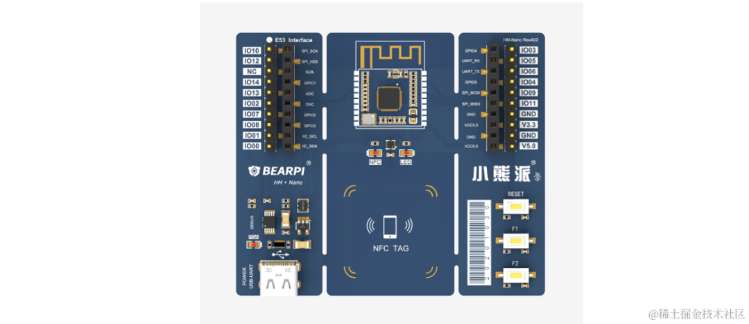
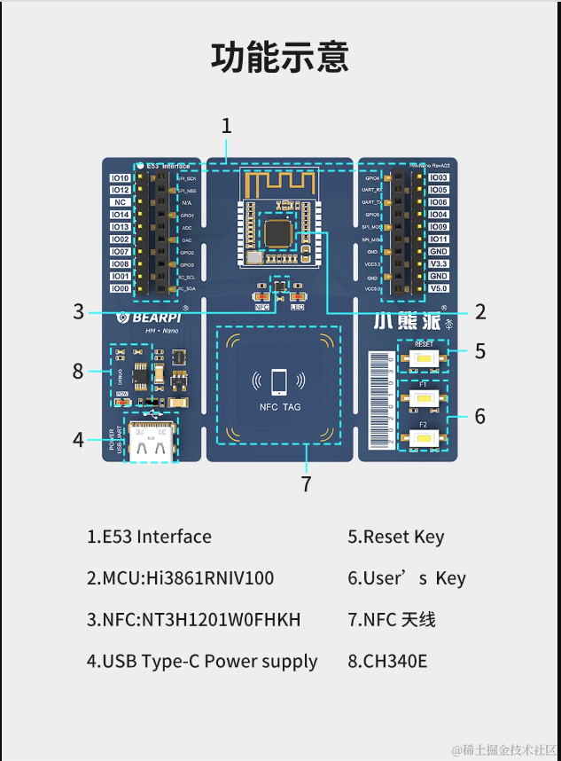
Below is the functional diagram of the BearPi-HM Nano development board:

2. Activate Huawei Cloud IoT Platform
Before setting up the development board environment, first activate the IoT platform and create a product for device cloud testing.
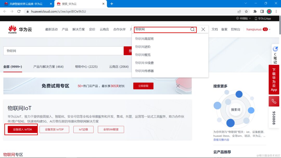
Huawei Cloud official website: https://www.huaweicloud.com/
Open the official website, search for IoT, and you can quickly find Device Access IoTDA.
2.1 Introduction to the IoT Platform
The Huawei Cloud IoT platform (IoT device access cloud service) provides massive device access and management capabilities, connecting physical devices to the cloud, supporting device data collection to the cloud and sending commands from the cloud to devices for remote control. Coupled with other Huawei Cloud products, it helps us quickly build IoT solutions.
Building a complete IoT solution using the IoT platform mainly includes three parts: the IoT platform, business applications, and devices.
The IoT platform acts as an intermediary layer connecting business applications and devices, shielding various complex device interfaces, enabling rapid device access; it also provides powerful open capabilities, supporting industry users in building various IoT solutions.
Devices can access the IoT platform through various networks such as wired, 2G/3G/4G/5G, NB-IoT, and Wifi, and use LWM2M/CoAP, MQTT, HTTPS protocols to report business data to the platform, which can also send control commands to devices.
Business applications can collect device data, issue commands, and manage devices through the APIs provided by the IoT platform.

2.2 Activate IoT Service
Address: https://www.huaweicloud.com/product/iothub.html

Upon entering, it will prompt to activate the standard version; there is no basic version after January 1, 2023.

After activation, click Overview to view access information. Our current device is preparing to use the MQTT protocol to connect to the Huawei Cloud platform, where you can see the address and port number for the MQTT protocol.

Summary:
Port number:   MQTT (1883)| MQTTS (8883)
Access address: 7445c6bcd3.st1.iotda-app.cn-north-4.myhuaweicloud.com
Obtain IP address information based on the domain name:
Microsoft Windows [Version 10.0.19044.2728]
(c) Microsoft Corporation. All rights reserved.

C:\Users\11266>ping 7445c6bcd3.st1.iotda-device.cn-north-4.myhuaweicloud.com

Pinging 7445c6bcd3.st1.iotda-device.cn-north-4.myhuaweicloud.com [117.78.5.125] with 32 bytes of data:
Reply from 117.78.5.125: bytes=32 time=42ms TTL=30
Reply from 117.78.5.125: bytes=32 time=35ms TTL=30
Reply from 117.78.5.125: bytes=32 time=36ms TTL=30
Reply from 117.78.5.125: bytes=32 time=36ms TTL=30

Ping statistics for 117.78.5.125:
    Packets: Sent = 4, Received = 4, Lost = 0 (0% loss),
Approximate round trip times in milliseconds:
    Minimum = 35ms, Maximum = 42ms, Average = 37ms

C:\Users\11266>

The MQTT protocol access port has two: 1883 is the unencrypted port, and 8883 is the certificate encrypted port. The microcontroller cannot load the certificate, so using port 1883 is more appropriate. The following ESP8266 will use port 1883 to connect to the Huawei Cloud IoT platform.
2.3 Create Product
(1) Create Product
Click on the product page, then click the upper left corner to create a product.

(2) Fill in Product Information
Fill in based on your product name.

(3) Product Created Successfully

(4) Add Custom Model
After the product is created, click to enter the product details page, scroll to the bottom to see the model definition.
First, click on the custom model.

Then create a service ID.

Next, click to add attributes.

2.4 Add Device
The product is an upper-level abstract model; next, add actual devices under the product model. The added devices ultimately need to be associated with real devices to complete data interaction.
(1) Register Device

(2) Fill in Based on Your Device

(3) Save Device Information
After creating, click save and close to get the created device key information. This information will be needed later when generating the MQTT tuple.

(4) Device Created Successfully

2.5 MQTT Protocol Topic Subscription and Publishing
(1) Introduction to MQTT Protocol
The current device uses the MQTT protocol to communicate with the Huawei Cloud platform.
MQTT is an IoT transmission protocol designed for lightweight publish/subscribe message transmission, aimed at providing reliable network services for IoT devices in low bandwidth and unstable network environments. MQTT is a lightweight transmission protocol developed specifically for IoT. It has been specially optimized for low bandwidth networks and devices with low computing power, making it suitable for various IoT application scenarios. Currently, MQTT has clients on various platforms and devices, forming an initial ecosystem.
MQTT is a message queue protocol that uses a publish/subscribe message model, providing one-to-many message publishing, decoupling application programs, and making development simpler compared to other protocols; the MQTT protocol operates over TCP/IP; it relies on TCP/IP to provide a stable network connection; therefore, any network device with a TCP protocol stack can use the MQTT protocol. The ESP8266 used in this device has a TCP protocol stack and can establish a TCP connection, so with the MQTT protocol encapsulated in the STM32 code, it can communicate with the Huawei Cloud platform.
The Huawei Cloud MQTT protocol access help documentation is available here: https://support.huaweicloud.com/devg-iothub/iot_02_2200.html

Business Process:

(2) Huawei Cloud Platform MQTT Protocol Usage Restrictions
| Description | Restriction |
|---|---|
| Supported MQTT Protocol Version | 3.1.1 |
| Differences from Standard MQTT Protocol | Supports QoS 0 and QoS 1, supports custom Topic, does not support QoS 2, does not support will, retain msg |
| MQTTS Supported Security Level | Uses TCP channel base + TLS protocol (up to TLSv1.3 version) |
| Maximum MQTT Connection Requests per Second per Account | No Limit |
| Maximum MQTT Connections per Minute per Device | 1 |
| Throughput per Second per MQTT Connection (including direct-connected devices and gateways) | 3KB/s |
| Maximum Length of a Single MQTT Publish Message | 1MB |
| Recommended Heartbeat Time for MQTT Connection | Heartbeat time is limited to 30 to 1200 seconds, recommended to set to 120 seconds |
| Does the Product Support Custom Topics | Yes |
| Message Publishing and Subscription | Devices can only publish and subscribe to their own Topics |
| Maximum Subscription Requests per Subscription Request | No Limit |
(3) Topic Subscription Format
Help documentation address: https://support.huaweicloud.com/devg-iothub/iot_02_2200.html

For devices, they generally subscribe to the topic for messages sent to devices by the platform.
If a device wants to receive messages sent from the platform, it needs to subscribe to the topic for messages sent to devices. After subscribing, when the platform sends messages to devices, the devices will receive them.
If a device wants to know the messages sent from the platform, it needs to subscribe to the topic indicated in the image above.
For the current device, the final subscription topic format is as follows:
$oc/devices/{device_id}/sys/messages/down

Final format:
$oc/devices/6419627e40773741f9fbdac7_dev1/sys/messages/down
(4) Topic Publishing Format
For devices, topic publishing means uploading data to the cloud platform, reporting the latest sensor data and device status to the cloud platform.
This operation is called: property reporting.
Help documentation address: https://support.huaweicloud.com/usermanual-iothub/iot_06_v5_3010.html

Based on the introduction from the help documentation, the current device’s publishing topic and property reporting format is summarized as follows:
Publishing topic format:
$oc/devices/{device_id}/sys/properties/report

Final format:
$oc/devices/6419627e40773741f9fbdac7_dev1/sys/properties/report
Publishing topics require uploading data in JSON format.

The uploaded JSON data format is as follows:

{
  "services": [
    {
      "service_id": <fill service ID>,
      "properties": {
        "<fill property name 1>": <fill property value>,
        "<fill property name 2>": <fill property value>,
        ..........
      }
    }
  ]
}
According to this JSON format, multiple property fields can be uploaded at once. The service ID, property field names, and property value types in this JSON format were introduced when creating the product; if forgotten, you can refer back to the earlier sections.

Based on this format, the combined property data for upload is:
{"services": [{"service_id": "stm32","properties":{"DS18B20":18,"motor_water":1,"motor_oxygen":1,"temp_max":10,"water_hp":130,"motor_food":0,"time_food":0,"oxygen_food":3}}]}
2.6 MQTT Tuple
Logging into the MQTT protocol requires filling in user ID, device ID, device password, etc., similar to how we log into QQ or WeChat by entering an account and password. These three parameters for logging into the MQTT protocol are generally called the MQTT tuple.
Next, I will introduce how to obtain the MQTT tuple parameters for the Huawei Cloud platform.
(1) MQTT Server Address
To log into the MQTT server, first remember to know the server address and port number.
Help documentation address: https://console.huaweicloud.com/iotdm/?region=cn-north-4#/dm-portal/home

The MQTT protocol ports support 1883 and 8883; their difference is that 8883 is the encrypted port, which is safer. However, it is more difficult to use on microcontrollers, so the current device uses port 1883 to connect.
Based on the above domain name and port number, the following IP address and port number information can be obtained: If the device supports filling in the domain name, you can directly fill in the domain name; if not supported, directly fill in the IP address. (The IP address is obtained from domain name resolution.)
Huawei Cloud MQTT server address: 114.116.232.138
Domain: 7445c6bcd3.st1.iotda-device.cn-north-4.myhuaweicloud.com
Huawei Cloud MQTT port number: 1883
(2) Generate MQTT Tuple
Huawei Cloud provides an online tool to generate the MQTT authentication tuple: https://iot-tool.obs-website.cn-north-4.myhuaweicloud.com/
Open this tool, fill in the device information (which is the information saved after creating the device), click generate, and you can obtain the MQTT login information.
Below is the opened page:

Fill in the device information: (The above two lines are the information saved after creating the device)
Directly get the tuple information.


After obtaining the tuple, the device side can fill in the parameters when logging in for authentication using the MQTT protocol.
ClientId 6419627e40773741f9fbdac7_dev1_0_0_2023032108
Username 6419627e40773741f9fbdac7_dev1
Password 861ac9e6a579d36888b2aaf97714be7af6c77017b017162884592bd68b086a6e
3.7 Simulate Device Login Test
After the above steps, the product, device, data model have been created, and the MQTT login information is obtained. Next, use MQTT client software to simulate a real device logging into the platform to test if communication with the server is normal.
(1) Fill in Login Information
Open the MQTT client software, fill in the relevant information (as introduced in the above text). Then, click login, subscribe to the topic, and publish the topic.

(2) Open the Web Page to View
After completing the above operations, open the Huawei Cloud web backend to see that the device is online.
Click on the details page to see the uploaded data.
At this point, the deployment on the cloud platform has been completed, and the device can upload data normally.
3. Setting Up the BearPi-HM_Nano Development Board Environment
3.1 Environment Introduction
In embedded development, many developers are accustomed to using Windows for code editing, compiling, and debugging downloads. For example, using IDEs like Keil, IAR, or Visual Studio Code.
However, at the current stage, the OpenHarmony source code does not support compilation in the Windows environment, such as the Hi3861 and Hi3516 series development boards. It needs to be done in a Linux environment, and it is recommended to use the Ubuntu compilation environment to compile the source code.
Setting up the Ubuntu system development environment can also be relatively troublesome, requiring the installation of many libraries, and may encounter various issues such as network problems or problems with the Ubuntu system’s repository sources that prevent downloads, etc. Beginners who are not familiar with Linux may find it a bit daunting.
The official tutorial provides two ways to quickly set up the environment.
(1) Install a virtual machine, install the Ubuntu system, and then follow the tutorial to install various libraries to complete the setup of the compilation environment.
(2) Install a virtual machine, download the official image, extract it, and run it directly. — This method is the simplest, equivalent to bringing over a computer with the environment already set up by someone else, without having to deal with environment setup issues; it is the most convenient.
Tutorial address: https://gitee.com/bearpi/bearpi-hm_nano/blob/master/applications/BearPi/BearPi-HM_Nano/docs/quick-start/BearPi-HM_Nano%E5%8D%81%E5%88%86%E9%92%9F%E4%B8%8A%E6%89%8B.md
3.2 Download Required Images
-
Download the official image provided
-
Download address (Baidu Cloud): https://pan.baidu.com/s/1T0Tcl3y48C1p5L6y-6HJNg Extraction code: eusr
-
Download HiBurn
-
Download address (Baidu Cloud): https://pan.baidu.com/s/1bp2ypAfH2HaNPTY2KwEhEA Extraction code: 1234
-
Download and install VMware Workstation virtual machine
-
Download address: https://www.vmware.com/products/workstation-player/workstation-player-evaluation.html
-
Download and install MobaXterm tool
-
Download address: https://en.softonic.com/download/moba/windows/post-download
-
Download and install RaiDrive tool
-
Download address: https://forspeed.rbread05.cn/down/newdown/5/28/RaiDrive.rar
-
Download and install the development board USB driver
-
Download address: http://www.wch.cn/search?q=ch340g&t=downloads
-
Download and install VS Code
-
Download address: https://code.visualstudio.com
3.3 Running the Ubuntu System
(1) First, install the VMware Workstation virtual machine, just install the latest version.
(2) Extract the Baidu Cloud downloaded HarmonyOS Ubuntu18.4 image OVF.zip file to a certain directory.

(3) Open the VMware Workstation tool

(4) Select the Ubuntu18.4 image OVF folder extracted in step 2, and click Open

(5) Import the image to the local disk (select a disk space size ≥ 10G), click Import.

(6) Click Power on this virtual machine to power on the virtual machine

(7) The virtual machine will enter the login interface; click HarmonyOS

(8) Enter the password: bearpi, then click Login

(9) After entering the desktop, right-click on the blank area of the desktop and click Open Terminal (E)

-
In the terminal, enter
ifconfig, then press enter; except forlo, the other one is your network card information, record the IP address you obtained.

(11) Minimize VMware Workstation and return to the Windows desktop.
(12) Note: If you cannot connect to the network, in VMware Workstation, click Virtual Machine>> Settings

Then in the network adapter, change to NAT Mode, click OK

Then restore Step 9.
3.4 Remote Connection to the Server from Windows
(1) Open the MobaXterm tool and click: Session, then the SSH button.

(2) Enter the connection information, remote address, and click OK

(3) Enter the account: bearpi, press enter

(4) Enter the password: bearpi, note that the password will not be displayed on the screen; after entering, click Enter

(5) In the pop-up interface, click Yes to save account information to avoid entering it next time

3.5 Map Ubuntu Files Remotely to Windows
(1) Install RaiDrive software
Follow the prompts to click next to install, all options default.
(2) Switch to Chinese language

(3) Add connection information
-
Uncheck read-only
-
SFTP:// __ enter the IP address obtained earlier
-
Account: both the account and password are bearpi
-
Other defaults
-
Click
OK

(4) View the local mapped Ubuntu file path

3.6 Obtain Source Code in Ubuntu
(1) Move the mouse focus to MobaXterm
(2) In MobaXterm, enter:
cd /home/bearpi
Then press enter
(3) In MobaXterm, enter:
mkdir project && cd project
Then press enter
(4) In MobaXterm, enter:
hpm init -t default
Then press enter
(5) In MobaXterm, enter:
hpm i @bearpi/bearpi_hm_nano
Then press enter, wait 1-3 minutes (depending on network speed)
(6) When Installed. appears on the screen, it means the code has been obtained successfully

The source code can also be directly downloaded from Gitee. Clone a single code repository by executing the command, for example:
git clone https://gitee.com/bearpi/bearpi-hm_nano.git -b master

Execute the following command to compile the source code
python build.py BearPi-HM_Nano
3.7 Compile Code
(1) In MobaXterm, enter:
hpm dist
Then press enter, wait until the screen shows: BUILD SUCCESS, indicating that the compilation was successful.
(2) Check the location of the compiled firmware
After compilation, you can directly view the final compiled firmware in Windows, the specific path is:

3.8 Connect Development Board
(1) Use a Type-C data cable to connect the computer to the BearPi-HM Nano.
(2) Install the CH340 driver.
Download address: http://www.wch.cn/search?q=ch340g&t=downloads
(3) If the virtual machine has seized the USB, you can pause the virtual machine first, then unplug and reinsert the USB.
(4) Check the serial port of the development board

3.9 Download Program
(1) Open the Hiburn tool in Windows, click Refresh, and select the COM number seen in COM

Then click Setting, and select Com settings,
(2) In Com settings, set Baud to: 921600, click OK

(3) Click the Select file button in the Hiburn tool, select the Hi3861_wifiiot_app_allinone.bin file.

(4) Check the Auto burn checkbox, then click Connect

At this point, the Connect button changes to Disconnect, wait for the download
(5) Reset the development board by pressing the RESET button to start downloading the program


(6) Wait until the screen shows Execution Successful, indicating that the program download is complete.
(7) After downloading, click the Disconnect button for future debugging use.
3.10 MobaXterm View Serial Port Print Log
(1) Open MobaXterm,
(2) Click: Session, Serial button
(3) Set Serial port to the same serial port as Hiburn
(4) Set Speed to 115200
(5) Click OK

(6) Reset the development board, at this point the COM will print out the corresponding log information

4. Connecting to Huawei Cloud IoT Platform
4.1 Introduction to MQTT Related Functions
(1) Set Device Information
void device_info_init(char *client_id, char * username, char *password);
Set device information; this must be set before calling oc_mqtt_init().

(2) Initialize Huawei IoT Platform
int oc_mqtt_init(void);
Function to initialize Huawei IoT platform; this must be called before using Huawei IoT platform functionality.

(3) Set Command Response Function
void oc_set_cmd_rsp_cb(void(*cmd_rsp_cb)(uint8_t *recv_data, size_t recv_size, uint8_t **resp_data, size_t *resp_size));
Set command response callback function.

(4) Device Message Reporting
int oc_mqtt_profile_msgup(char *deviceid,oc_mqtt_profile_msgup_t *payload);
When a device cannot report data in the format defined in the product model, this interface can be called to report the device's custom data to the platform, which will forward the reported message to the application server or other Huawei Cloud services for storage and processing.

(5) Device Reporting Attribute Data
int oc_mqtt_profile_propertyreport(char *deviceid,oc_mqtt_profile_service_t *payload);
Used for devices to report attribute data to the platform in the format defined in the product model.

(6) Gateway Batch Reporting Attribute Data
int oc_mqtt_profile_gwpropertyreport(char *deviceid,oc_mqtt_profile_device_t *payload);
Used for batch devices to report attribute data to the platform. Gateway devices can use this interface to report attribute data of multiple sub-devices simultaneously to the platform.

(7) Response Result of Attribute Setting
int oc_mqtt_profile_propertysetresp(char *deviceid,oc_mqtt_profile_propertysetresp_t *payload);

(8) Response Result of Attribute Query
int oc_mqtt_profile_propertygetresp(char *deviceid,oc_mqtt_profile_propertygetresp_t *payload);

(9) Return the execution result of the command to the platform
int oc_mqtt_profile_cmdresp(char *deviceid,oc_mqtt_profile_cmdresp_t *payload);
After the platform issues a command, the device needs to return the command execution result to the platform in a timely manner. If the device does not respond, the platform will consider the command execution timed out.
4.2 Connect to the Platform
When connecting to the platform, you need to fill in CLIENT_ID, USERNAME, PASSWORD in the device_info_init function. This information has been introduced in Chapter 2.
WifiConnect("da_666","12345678");
device_info_init(CLIENT_ID,USERNAME,PASSWORD);
oc_mqtt_init();
oc_set_cmd_rsp_cb(oc_cmd_rsp_cb);
Modify the iot_cloud_oc_sample.c file.

4.3 Upload Data
When data needs to be uploaded, it needs to be assembled first, and then reported through oc_mqtt_profile_propertyreport.
Sample code is as follows:
static void deal_report_msg(report_t *report)
{
    oc_mqtt_profile_service_t    service;
    oc_mqtt_profile_kv_t         temperature;
    oc_mqtt_profile_kv_t         humidity;
    oc_mqtt_profile_kv_t         luminance;
    oc_mqtt_profile_kv_t         led;
    oc_mqtt_profile_kv_t         motor;

    service.event_time = NULL;
    service.service_id = "Agriculture";
    service.service_property = &temperature;
    service.nxt = NULL;

    temperature.key = "Temperature";
    temperature.value = &report->temp;
    temperature.type = EN_OC_MQTT_PROFILE_VALUE_INT;
    temperature.nxt = &humidity;

    humidity.key = "Humidity";
    humidity.value = &report->hum;
    humidity.type = EN_OC_MQTT_PROFILE_VALUE_INT;
    humidity.nxt = &luminance;

    luminance.key = "Luminance";
    luminance.value = &report->lum;
    luminance.type = EN_OC_MQTT_PROFILE_VALUE_INT;
    luminance.nxt = &led;

    led.key = "LightStatus";
    led.value = g_app_cb.led?"ON":"OFF";
    led.type = EN_OC_MQTT_PROFILE_VALUE_STRING;
    led.nxt = &motor;

    motor.key = "MotorStatus";
    motor.value = g_app_cb.motor?"ON":"OFF";
    motor.type = EN_OC_MQTT_PROFILE_VALUE_STRING;
    motor.nxt = NULL;

    oc_mqtt_profile_propertyreport(USERNAME,&service);
    return;
}
4.4 Receiving Commands Issued by the Cloud Platform
The Huawei IoT platform supports issuing commands, which are user-defined. Upon receiving a command, the command data will be sent to the queue, and the task_main_entry function will read the queue data and call the deal_cmd_msg function for processing. Sample code is as follows:
void oc_cmd_rsp_cb(uint8_t *recv_data, size_t recv_size, uint8_t **resp_data, size_t *resp_size)
{
    app_msg_t *app_msg;

    int    ret = 0;
    app_msg = malloc(sizeof(app_msg_t));
    app_msg->msg_type = en_msg_cmd;
    app_msg->msg.cmd.payload = (char *)recv_data;

    printf("recv data is %.*s\n", recv_size, recv_data);
    ret = osMessageQueuePut(mid_MsgQueue,&app_msg,0U, 0U);
    if(ret != 0){
        free(recv_data);
    }
    *resp_data = NULL;
    *resp_size = 0;
}
static int task_main_entry( void )
{
    app_msg_t *app_msg;

    WifiConnect("TP-LINK_65A8","0987654321");
    device_info_init(CLIENT_ID,USERNAME,PASSWORD);
    oc_mqtt_init();
    oc_set_cmd_rsp_cb(oc_cmd_rsp_cb);

    while(1){
        app_msg = NULL;
        (void)osMessageQueueGet(mid_MsgQueue,(void **)&app_msg,NULL, 0U);
        if(NULL != app_msg){
            switch(app_msg->msg_type){
                case en_msg_cmd:
                    deal_cmd_msg(&app_msg->msg.cmd);
                    break;
                case en_msg_report:
                    deal_report_msg(&app_msg->msg.report);
                    break;
                default:
                    break;
            }
            free(app_msg);
        }
    }
    return 0;
}
static void deal_cmd_msg(cmd_t *cmd)
{
    cJSON *obj_root;
    cJSON *obj_cmdname;
    cJSON *obj_paras;
    cJSON *obj_para;

    int cmdret = 1;
    oc_mqtt_profile_cmdresp_t  cmdresp;
    obj_root = cJSON_Parse(cmd->payload);
    if(NULL == obj_root){
        goto EXIT_JSONPARSE;
    }

    obj_cmdname = cJSON_GetObjectItem(obj_root,"command_name");
    if(NULL == obj_cmdname){
        goto EXIT_CMDOBJ;
    }
    if(0 == strcmp(cJSON_GetStringValue(obj_cmdname),"Agriculture_Control_light")){
        obj_paras = cJSON_GetObjectItem(obj_root,"paras");
        if(NULL == obj_paras){
            goto EXIT_OBJPARAS;
        }
        obj_para = cJSON_GetObjectItem(obj_paras,"Light");
        if(NULL == obj_para){
            goto EXIT_OBJPARA;
        }
        ///< operate the LED here
        if(0 == strcmp(cJSON_GetStringValue(obj_para),"ON")){
            g_app_cb.led = 1;
            Light_StatusSet(ON);
            printf("Light On!\n");
        }
        else{
            g_app_cb.led = 0;
            Light_StatusSet(OFF);
            printf("Light Off!\n");
        }
        cmdret = 0;
    }
    else if(0 == strcmp(cJSON_GetStringValue(obj_cmdname),"Agriculture_Control_Motor")){
        obj_paras = cJSON_GetObjectItem(obj_root,"Paras");
        if(NULL == obj_paras){
            goto EXIT_OBJPARAS;
        }
        obj_para = cJSON_GetObjectItem(obj_paras,"Motor");
        if(NULL == obj_para){
            goto EXIT_OBJPARA;
        }
        ///< operate the Motor here
        if(0 == strcmp(cJSON_GetStringValue(obj_para),"ON")){
            g_app_cb.motor = 1;
            Motor_StatusSet(ON);
            printf("Motor On!\n");
        }
        else{
            g_app_cb.motor = 0;
            Motor_StatusSet(OFF);
            printf("Motor Off!\n");
        }
        cmdret = 0;
    }

EXIT_OBJPARA:
EXIT_OBJPARAS:
EXIT_CMDOBJ:
    cJSON_Delete(obj_root);
EXIT_JSONPARSE:
    ///< do the response
    cmdresp.paras = NULL;
    cmdresp.request_id = cmd->request_id;
    cmdresp.ret_code = cmdret;
    cmdresp.ret_name = NULL;
    (void)oc_mqtt_profile_cmdresp(NULL,&cmdresp);
    return;
}
4.6 Modify Platform Address
Modify the platform docking address around line 47 in oc_mqtt.h according to the platform version you are using.
This is determined based on your product; all new activations after January 1, 2023 are standard versions.

#ifndef LITEOS_LAB_IOT_LINK_OC_OC_MQTT_OC_MQTT_PROFILE_OC_MQTT_PROFILE_H_
#define LITEOS_LAB_IOT_LINK_OC_OC_MQTT_OC_MQTT_PROFILE_OC_MQTT_PROFILE_H_

#include <stdint.h>


#define OC_SERVER_URL              "tcp://183.230.40.39:6002"

// #define OC_SERVER_IP                "121.36.42.100"         // Basic version platform docking address
#define OC_SERVER_IP                "117.78.5.125"          // Standard version platform docking address

#define OC_SERVER_PORT              1883
#define OC_CLIENT_ID_LEN          128
#define OC_USERNAME_LEN         128
#define OC_PASSWORD_LEN          128
4.7 Compile and Burn Code
After modifying the code, compile and burn it. Press the RESET button on the development board, and check the logs through the serial port assistant; temperature, humidity, and light intensity information will be printed. Open the backend of the cloud platform to see that the device is online.