 Tip:Click the above ↑↑“CNC Expert“ to subscribe for free daily


⑴ Point Control CNC Machine Tools
Point control only requires accurate positioning of the moving parts of the machine tool from one point to another, with no strict requirements for the movement trajectory between points. During the movement, no processing occurs, and the movements between coordinate axes are unrelated. To achieve fast and precise positioning, the displacement between two points generally involves a rapid move followed by a slow approach to the target point to ensure positioning accuracy, as shown in the figure below, illustrating the movement trajectory of point control.
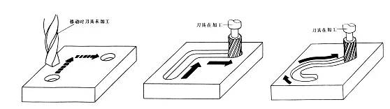
Machine tools with point control functions mainly include CNC drilling machines, CNC milling machines, and CNC punching machines. With the development of CNC technology and the reduction in the price of CNC systems, CNC systems solely used for point control have become rare.
⑵ Linear Control CNC Machine Tools
Linear control CNC machine tools, also known as parallel control CNC machine tools, are characterized by controlling not only the precise positioning between points but also the speed and trajectory of movement between two related points. However, the movement trajectory only moves parallel to the machine tool’s coordinate axes, meaning that only one coordinate axis is controlled simultaneously (i.e., the CNC system does not need interpolation calculation functions). During the displacement, the tool can perform cutting at a specified feed rate and is generally limited to processing rectangular and stepped parts.
The machine tools with linear control functions mainly include relatively simple CNC lathes, CNC milling machines, and CNC grinding machines. Such machine tools’ CNC systems are also referred to as linear control CNC systems. Similarly, CNC machine tools solely used for linear control are also rare.
⑶ Contour Control CNC Machine Tools
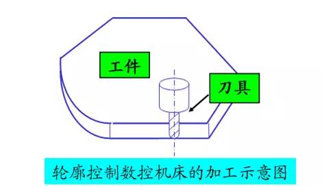
Contour control CNC machine tools, also known as continuous control CNC machine tools, are characterized by the ability to simultaneously control the displacement and speed of two or more motion coordinates.
To meet the requirements of the tool’s relative motion trajectory along the workpiece’s contour, the displacement control and speed control of each coordinate movement must be accurately coordinated according to specified proportional relationships.
Therefore, this control method requires the CNC device to have interpolation calculation functions. Interpolation refers to the mathematical processing by the interpolation calculator within the CNC system to describe the shape of lines or arcs based on the basic data input into the program (such as the endpoint coordinates of a line, the endpoint coordinates and center coordinates or radius of an arc). This means calculating while distributing pulses to each coordinate axis controller based on the calculation results, thereby controlling the linkage displacement of each coordinate axis to match the required contour. During the movement, the tool continuously cuts the surface of the workpiece, allowing for the processing of various lines, arcs, and curves.
This type of machine tool mainly includes CNC lathes, CNC milling machines, CNC wire-cutting machines, and machining centers. The corresponding CNC devices are referred to as contour control CNC systems. Depending on the number of coordinated axes they control, they can be further divided into the following forms:
① Two-Axis Linkage: Mainly used for CNC lathes to process rotating surfaces or CNC milling machines to process curved surfaces.
② Two-Axis Semi-Linkage: Mainly used for controlling machines with three or more axes, where two axes can be linked while the other axis can perform periodic feeding.
③ Three-Axis Linkage: Generally divided into two categories: one category is the linkage of the three linear coordinate axes X/Y/Z, commonly used in CNC milling machines, machining centers, etc. The other category controls two linear coordinates among X/Y/Z while also controlling a rotational coordinate axis that rotates around one of the linear coordinate axes.
For instance, in a turning machining center, it not only requires linkage of the longitudinal (Z-axis) and transverse (X-axis) linear coordinate axes but also needs to simultaneously control the spindle (C-axis) rotating around the Z-axis.
④ Four-Axis Linkage: Simultaneously controls three linear coordinate axes X/Y/Z and a rotational coordinate axis.
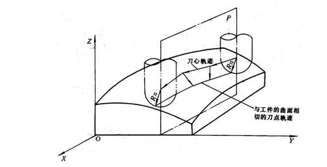
⑤ Five-Axis Linkage: In addition to simultaneously controlling the three linear coordinate axes X/Y/Z, it also simultaneously controls two of the A, B, C coordinate axes that rotate around these linear coordinate axes, forming a linkage of five axes. In this case, the tool can be fixed in any direction in space.
For example, controlling the tool to swing around both the X and Y axes, ensuring that the tool maintains a normal direction to the contour surface being processed at its cutting point, thus ensuring the smoothness of the processed contour surface, improving processing accuracy and efficiency, and reducing the roughness of the processed surface.
⑴ Open-Loop Control CNC Machine Tools
These machine tools have open-loop feeding servo drives, meaning there are no detection feedback devices. Generally, the driving motor is a stepper motor, characterized by the control circuit rotating one step angle for each change of command pulse signal, and the motor itself has self-locking capabilities.
The feeding command signals output by the CNC system control the driving circuit through a pulse distributor, controlling the coordinate displacement by changing the number of pulses, controlling the displacement speed by changing the pulse frequency, and controlling the displacement direction by changing the pulse distribution order.
Therefore, the main feature of this control method is easy control, simple structure, and low cost. The signal flow of the commands issued by the CNC system is unidirectional, so there is no stability issue in the control system. However, since mechanical transmission errors are not corrected through feedback, the displacement accuracy is not high.
Early CNC machine tools all used this control method, but they had a relatively high failure rate. Currently, due to improvements in driving circuits, they are still widely used, especially in China, where general economic CNC systems and retrofits of old equipment often adopt this control method. Additionally, this control method can be configured with microcontrollers or single-board computers as CNC devices, reducing the overall system cost.
⑵ Closed-Loop Control Machine Tools
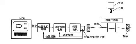
These CNC machine tools operate using closed-loop feedback control for their feeding servo drives, and their driving motors can use either DC or AC servo motors, requiring the configuration of position feedback and speed feedback. During processing, the actual displacement of the moving parts is detected in real-time and fed back to the comparator in the CNC system, which compares it with the command signals obtained from interpolation calculations. The difference is then used as the control signal for the servo drive, driving the displacement components to eliminate displacement errors.
Depending on the installation position of the position feedback detection element and the type of feedback device used, it can be divided into two control methods: full closed-loop and semi-closed-loop.
① Full Closed-Loop Control
As shown in the figure, the position feedback device uses linear displacement detection elements (currently generally using grating rulers), installed at the saddle of the machine tool, directly detecting the linear displacement of the machine tool coordinates. Through feedback, it can eliminate transmission errors in the entire mechanical transmission chain from the motor to the machine tool saddle, thus achieving high static positioning accuracy.
However, due to the non-linear characteristics of friction, rigidity, and gaps in many mechanical transmission links within the entire control loop, and the dynamic response time of the entire mechanical transmission chain being much larger than the electrical response time, this poses significant challenges for stability correction in the entire closed-loop system. The design and adjustment of the system are also quite complex. Therefore, this full closed-loop control method is mainly used for CNC coordinate boring machines, CNC precision grinding machines, etc., which require high precision.
② Semi-Closed-Loop Control
As shown in the figure, its position feedback uses angular detection elements (currently mainly using encoders), directly installed at the servo motor or the end of the screw. Since most mechanical transmission links are not included in the system’s closed-loop, it can achieve relatively stable control characteristics. Mechanical transmission errors such as screw errors cannot be corrected through feedback at all times, but software compensation methods can be used to improve accuracy appropriately. Currently, most CNC machine tools adopt semi-closed-loop control methods.
⑶ Hybrid Control CNC Machine Tools
By selectively concentrating the characteristics of the above control methods, a hybrid control scheme can be formed. As mentioned earlier, since the open-loop control method has good stability, low cost, and poor precision, while the full closed-loop has poor stability, a hybrid control method is recommended to meet the control requirements of certain machine tools. The more commonly used methods are open-loop compensation types and semi-closed-loop compensation types.
According to the functional level of the CNC system, CNC systems are usually divided into three categories: low, medium, and high. This classification method is commonly used in China. The boundaries between low, medium, and high are relative, and the classification standards may differ at different times. Based on the current development level, CNC systems can be classified into low, medium, and high-end types based on certain functions and indicators. Among them, medium and high-end are generally referred to as fully functional CNC or standard CNC.
⑴ Metal Cutting Type
Refers to CNC machine tools that use various cutting processes such as turning, milling, punching, reaming, drilling, grinding, and planing. It can be further divided into the following two categories.
① Ordinary CNC Machine Tools, such as CNC lathes, CNC milling machines, CNC grinding machines, etc.
② Machining Centers, characterized by an automatic tool-changing mechanism in the tool library, allowing for continuous processing of various workpiece surfaces through automatic tool changes after a single clamping of the workpiece, such as (boring/milling) machining centers, turning centers, drilling centers, etc.
⑵ Metal Forming Type
Refers to CNC machine tools that use forming processes such as extrusion, punching, pressing, and stretching, commonly including CNC presses, CNC bending machines, CNC pipe bending machines, and CNC spinning machines.
⑶ Special Processing Type
Mainly includes CNC electrical discharge wire-cutting machines, CNC electrical discharge forming machines, CNC flame cutting machines, CNC laser processing machines, etc.
⑷ Measurement and Drawing Type
Mainly includes coordinate measuring machines, CNC tool setting instruments, CNC plotters, etc.