1. Memory Mapping In the memory mapping diagram of the STM32F429 chip, it can be seen that the peripherals are allocated 512M of space; however, the actual peripherals do not utilize the entire 512M of memory. When operating peripherals, it is sufficient to manipulate their corresponding memory addresses. For more detailed peripheral memory addresses, refer to the Memory map section of the chip’s user manual (not the data sheet).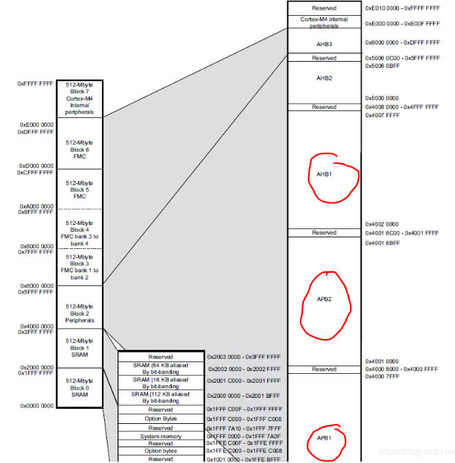 The microcontroller maps peripherals to memory addresses, allowing peripherals to be operated like memory (write/read). When operating memory, it is done through addresses. Since the microcontroller has already mapped the peripherals to memory, it is only necessary to operate the memory addresses mapped to the peripherals when working with microcontroller peripherals.
How to Operate Memory?
In C language, memory can be manipulated using pointers. In assembly language, since there is no concept of pointers, address manipulation can only be accomplished using certain memory read/write instructions, such as: LDR, STR.
Comparison of Struct Operations and Macro Definitions
C Language – Macro Definition Form:
#define GPIOA (*(volatile uint32_t *)(0x000800E0))#define GPIOA_DR (*(volatile uint32_t *)(0x000800E4))#define GPIOA_MR (*(volatile uint32_t *)(0x00080108))#define GPIOA_TR (*(volatile uint32_t *)(0x00080108))C Language – Struct Operation:
struct GPIOA_Reg{ volatile uint32_t dr; volatile uint32_t mr; volatile uint32_t tr;}GPIOA_REG;Assembly Language Memory Operations
LDR r0, =0x00800010MOV r1, #2STR r1, [r0]2. Register Method
Code Structure Framework:
File Structure
A chip header file: macro definitions for peripheral addresses and definitions of related structures.Refer to the chip’s user manual (note: not the data sheet) for the corresponding addresses of the registers. Then use macro definitions to define them, while also defining structures to manage the peripheral register groups more conveniently.
- A startup file: written in assembly, including the interrupt vector table, etc.
- The user code file: the remaining part is the user code file.
- Writing peripheral driver functions for various chips (read/write, control), as well as user logic code.
3. Using HAL Library Method
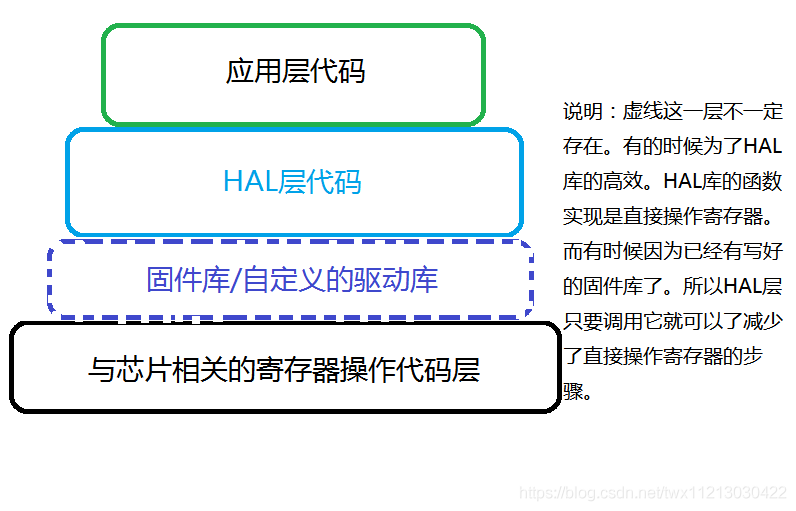
HAL Library Design
1. HAL Framework Design
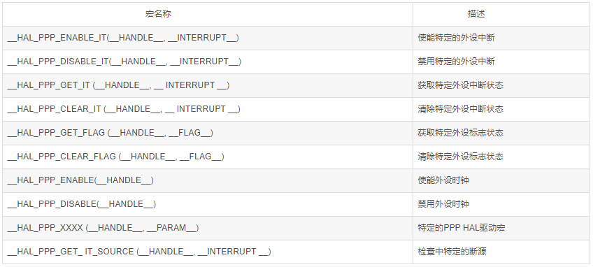
2. HAL Resource Naming Rules
HAL function naming rules:
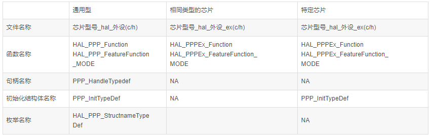
Macros for interrupt and clock settings:
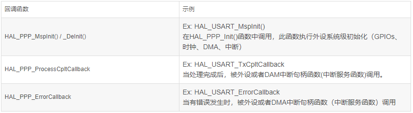
Callback function naming rules:
3. File Structure:
A chip header file: macro definitions for peripheral addresses and definitions of related structures.Refer to the chip’s user manual (note: not the data sheet) for the corresponding addresses of the registers. Then use macro definitions to define them, while also defining structures to manage the peripheral register groups more conveniently. Here, the STM32F1 series is used as an example.A startup file: written in assembly, including the interrupt vector table, etc.A global header file for the HAL library: some global macro definitions and includes for other peripheral header files.HAL library files: driver functions for the chip’s peripherals.
4. Explanation of HAL Library Components
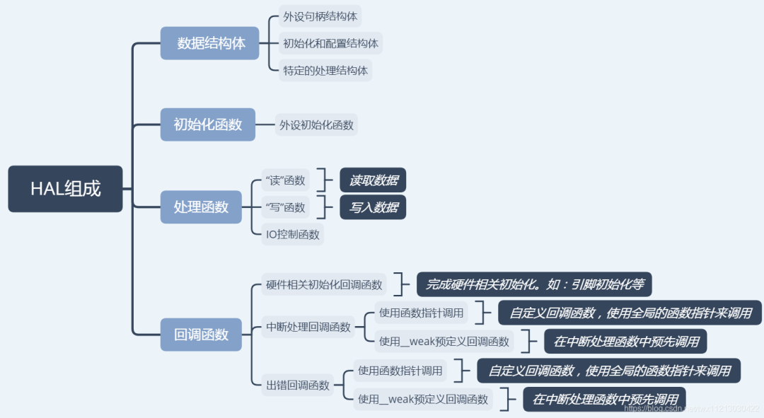
HAL Library Data Structures
-
• Peripheral handle structure
-
• Initialization and configuration structure
- • Specific processing structure (read/write/control)
Peripheral handle structure (not hardware-related):For example, the following is a UART structure
typedef struct{ USART_TypeDef *Instance; /* USART registers base address */ USART_InitTypeDef Init; /* Usart communication parameters */ uint8_t *pTxBuffPtr;/* Pointer to Usart Tx transfer Buffer */ uint16_t TxXferSize; /* Usart Tx Transfer size */ __IO uint16_t TxXferCount;/* Usart Tx Transfer Counter */ uint8_t *pRxBuffPtr;/* Pointer to Usart Rx transfer Buffer */ uint16_t RxXferSize; /* Usart Rx Transfer size */ __IO uint16_t RxXferCount; /* Usart Rx Transfer Counter */ DMA_HandleTypeDef *hdmatx; /* Usart Tx DMA Handle parameters */ DMA_HandleTypeDef *hdmarx; /* Usart Rx DMA Handle parameters */ HAL_LockTypeDef Lock; /* Locking object */ __IO HAL_USART_StateTypeDef State; /* Usart communication state */ __IO HAL_USART_ErrorTypeDef ErrorCode;/* USART Error code */}USART_HandleTypeDef;Initialization structure (hardware-related):For example, the following is a UART hardware-related structure
typedef struct{ uint32_t BaudRate; /*!< This member configures the UART communication baudrate.*/ uint32_t WordLength; /*!< Specifies the number of data bits transmitted or received in a frame.*/ uint32_t StopBits; /*!< Specifies the number of stop bits transmitted.*/ uint32_t Parity; /*!< Specifies the parity mode. */ uint32_t Mode; /*!< Specifies whether the Receive or Transmit mode is enabled or disabled.*/ uint32_t HwFlowCtl; /*!< Specifies whether the hardware flow control mode is enabled or disabled.*/ uint32_t OverSampling; /*!< Specifies whether the Over sampling 8 is enabled or disabled, to achieve higher speed (up to fPCLK/8).*/}UART_InitTypeDef;Specific processing structure (hardware-related):For example, the following is an ADC processing structure
typedef struct { uint32_t Channel; /*!< Specifies the channel to configure into ADC regular group. This parameter can be a value of @ref ADC_channels */ uint32_t Rank; /*!< Specifies the rank in the regular group sequencer. This parameter must be a number between Min_Data = 1 and Max_Data = 16 */ uint32_t SamplingTime; /*!< Sampling time value to be set for the selected channel. Unit: ADC clock cycles Conversion time is the addition of sampling time and processing time (12 ADC clock cycles at ADC resolution 12 bits, 11 cycles at 10 bits, 9 cycles at 8 bits, 7 cycles at 6 bits). This parameter can be a value of @ref ADC_sampling_times Caution: This parameter updates the parameter property of the channel, that can be used into regular and/or injected groups. If this same channel has been previously configured in the other group (regular/injected), it will be updated to last setting. Note: In case of usage of internal measurement channels (VrefInt/Vbat/TempSensor), sampling time constraints must be respected (sampling time can be adjusted in function of ADC clock frequency and sampling time setting) Refer to device datasheet for timings values, parameters TS_vrefint, TS_temp (values rough order: 4us min). */ uint32_t Offset; /*!< Reserved for future use, can be set to 0 */}ADC_ChannelConfTypeDef;Common Resources in HAL Library
HAL Status: Status enumeration
Typedef enum{ HAL_OK = 0x00, HAL_ERROR = 0x01, HAL_BUSY = 0x02, HAL_TIMEOUT = 0x03} HAL_StatusTypeDef;HAL Locked: Used to prevent accidental access to shared resources
typedef enum{HAL_UNLOCKED = 0x00, /*!<Resources unlocked */HAL_LOCKED = 0x01 /*!< Resources locked */} HAL_LockTypeDef;Common macro definitions: NULL and HAL_MAX_DELAY
#ifndef NULL#define NULL (void *) 0#endif#define HAL_MAX_DELAY 0xFFFFFFFFImplementation of Interrupt Callback Functions in HAL Library
(1) Use __ weak to define the callback function. If the user rewrites the callback function, the compiler will use the user-defined callback function. The __ weak keyword is defined by the compiler.(2) Use function pointers. Define a global function pointer variable, and during the initialization function, assign our custom callback function to this global function pointer variable (this step is also called: registration). Then in the interrupt function, call our custom callback function through this global function pointer variable.
Original text: https://blog.csdn.net/twx1121303042 Disclaimer: This account maintains neutrality regarding all original and reprinted articles' statements and viewpoints. The articles are provided for readers' learning and communication purposes. The copyright of the articles, images, etc., belongs to the original authors.