For a complex microcontroller project, having a BootLoader (hereinafter referred to as BL) is very important. It makes maintaining and upgrading your application code much easier.
This article will help you understand why to design a Bootloader and how to design it, aiming to achieve a clear understanding of both its function and purpose.
Through a detailed explanation of BL, I hope everyone can appreciate its importance.
1. Evolution of Programming Methods
More Convenient ISP Programming Methods
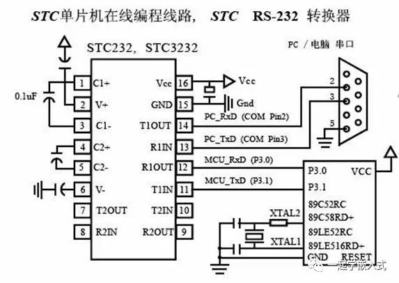
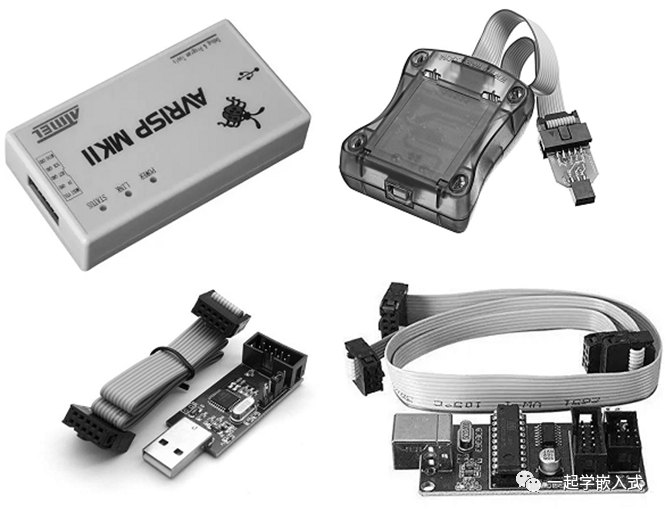
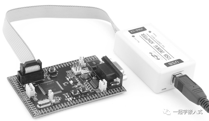
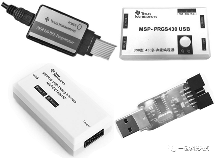
1. They rely on specialized host computers or downloader hardware, which cannot achieve uniformity;
1. Unified communication method (for example, all using serial);
2. Providing a friendly operating interface (for example, command line);
3. Efficient and fast, with no additional operations, preferably one-click automated programming;
4. Additionally, adding some embedded firmware management functions (such as firmware version management).
About Bootloader
Basic Form of Bootloader
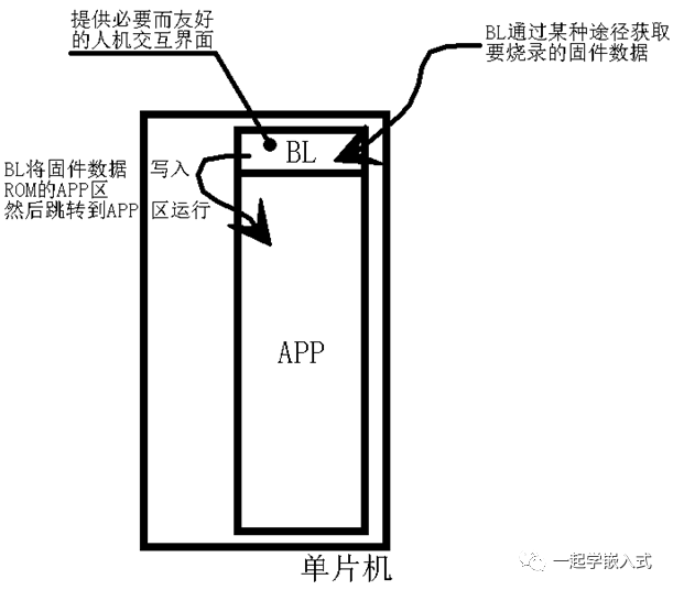
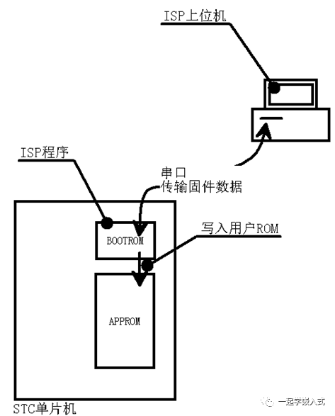
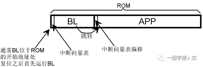
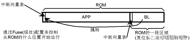
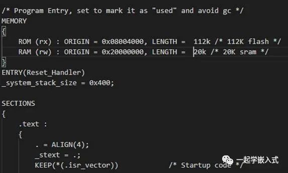
We can see that BL is a program stored in ROM that primarily implements four functions:
1. Obtain the firmware data to be programmed through some means;
2. Write the firmware data into the APP area of the ROM;
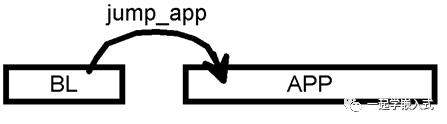
3. Jump to the APP area to run the user program that has been programmed;
Two Design Examples of Bootloader
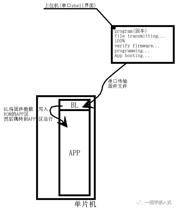
The basic operational logic is as follows:
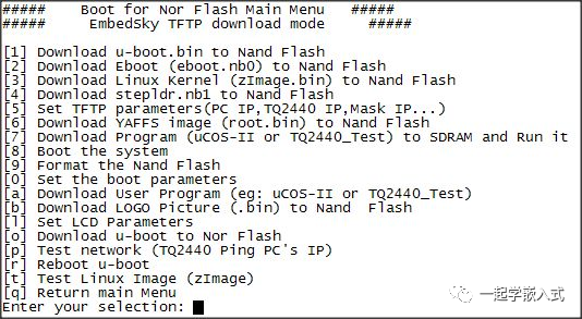
1. Input the command “program” through a serial terminal like HyperTerminal, SecureCRT, or Xshell;
2. The BL receives the command and starts waiting to receive firmware file data;
3. The serial terminal uses a file data transfer protocol (for example, X/Y/Zmodem protocol) to send the firmware data to the BL;
4. The BL writes the firmware data into the APP area of the ROM;
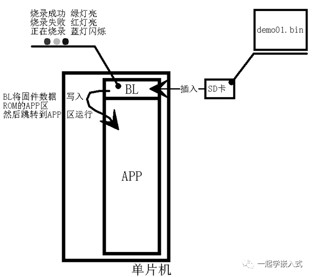
The basic operational logic is as follows:
1. Copy the firmware to be programmed onto the SD card;
2. Insert the SD card into the slot;
3. The BL detects the SD card insertion and searches for BIN files on the card;
4. The BL reads the BIN file data and writes it into the APP area of the ROM;
Key Points for Implementing BL
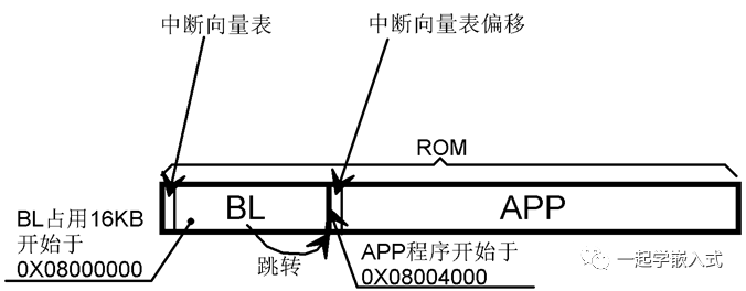
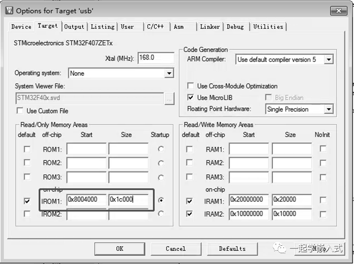
#define VECT_TAB_OFFSET 0x4000
typedef void (*iapfun)(void);
iapfun jump2app;
void MSR_MSP(u32 addr)
{
__ASM volatile("MSR MSP, r0"); //set Main Stack value*
__ASM volatile("BX r14");*
}
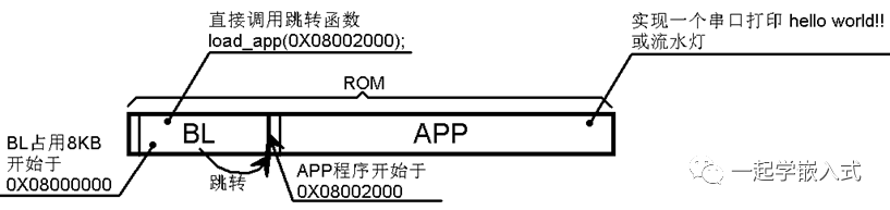
void load_app(u32 appxaddr)
{
if(((*(vu32*)appxaddr)&0x2FFE0000)==0x20000000)//**check if stack top address is valid*
{
//**User code area second word is program start address (**reset address)
jump2app=(iapfun)*(vu32*)(appxaddr+4);
//**Initialize APP** stack pointer (**first word of user code area stores stack top address)
MSR_MSP(*(vu32*)appxaddr);
jump2app(); //**Jump to APP.
}
}
Innovative Uses of Bootloader
The content I have presented above covers the most basic aspects of BL that are essential for us to understand. The true highlights of BL lie in the diverse methods of obtaining firmware data.
Implementation and Extension of BL (Firmware Transfer via Serial)
Earlier, I mentioned two applications of BL: one is transferring firmware files via serial, and the other is copying firmware files from an SD card. These are two forms of BL frequently used in practical engineering.
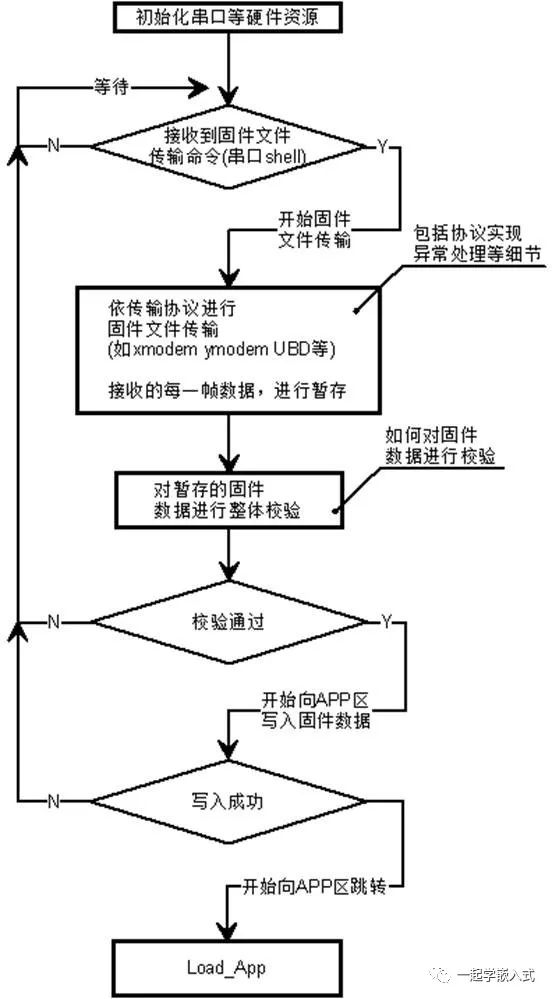
Here, I will focus on the implementation details of the former example, as it is very typical, as shown in the figure.
-
How is the serial communication protocol implemented? -
Why is the firmware data received from the host computer not written directly to the APP area but temporarily stored and verified first? -
How is the firmware data verified?
For the first question, the details of implementing the serial communication protocol and file transfer are somewhat complicated and will be explained in a future article.
For the second question: The firmware data received by the microcontroller through serial transfer may contain errors, and if erroneous firmware is written directly to the APP area, it will not run. Therefore, we need to temporarily store each frame of data, and after all data is transmitted, perform an overall verification to ensure the absolute correctness of the firmware data.
Regarding the third question, we need to focus on this.
How can we determine if a file has errors during transmission from the sender to the receiver?
The usual practice is to add a checksum to the file; the receiver calculates the checksum using the same method and compares it with the checksum in the file. If they match, the transmission is deemed correct, as shown in the figure.
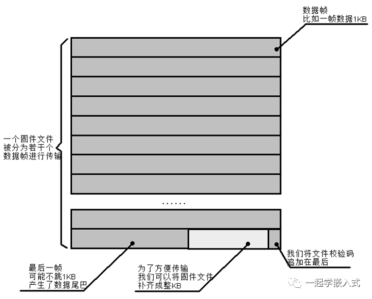
The above image illustrates the padding of the firmware file and the addition of the checksum.
Why do we need to pad the file? Embedded programs generated by cross-compilation into burnable files, such as BIN, are often not multiples of 128, 256, 512, or 1024. This can lead to the last frame of data being insufficient in length during transmission, resulting in a data tail.
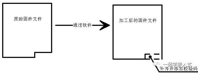
Padded rounding is the most direct method to resolve data tails. This operation is done on the host computer, usually by writing a small software to achieve it. This small software will also append the checksum to the end of the firmware file. This checksum can use a checksum or CRC, typically 16-bit or 32-bit, as shown, achieved by a small software that pads the firmware file and adds the checksum.
Someone might ask: “To temporarily store the entire firmware, doesn’t that require additional storage space, like external ROM (FlashROM or EEPROM)?
Yes. If we want to save costs, we can also program directly into the APP area without temporary storage. This is risky, but generally, it is not a big issue (STC and STM32’s serial ISP are actually real-time programming without temporary storage).
During the transmission process, the transmission protocol provides a certain guarantee for data correctness; it checks each frame of data, and if it fails, there will be retransmissions. Continuous failures may directly terminate the transmission. Therefore, as long as the transmission completes, the data’s correctness is generally assured.
However, it is still advisable to perform an overall verification of the firmware, and if cost allows, to slightly increase the ROM capacity. Additionally, firmware temporary storage has another benefit: if the firmware in the APP area is damaged, such as accidentally losing the firmware or erasing the APP area during IAP, we can recover it from the temporarily stored firmware (a complete BL will include firmware recovery functionality).
In fact, we do not necessarily need to expand the ROM; if the firmware size is relatively small, we can split the microcontroller’s on-chip ROM in half for use, using the latter half for firmware temporary storage. We can divide the on-chip ROM into three parts:
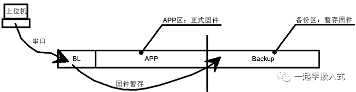
We divide the on-chip ROM into three parts, used for storing BL, APP firmware, and temporarily storing firmware. For example, we use STM32F103RBT6, which has a total ROM capacity of 128KB, divided into 16K/56K/56K.
Some products are extremely cost-sensitive. I have had such development experiences; the microcontroller used was STM32F103C8T6, with a total on-chip ROM capacity of 64K and a firmware size of 48K, with the BL being 12K. During firmware programming using BL, there was no extra ROM for temporary storage. I employed a trick called “tailing the dog” as shown in the figure.
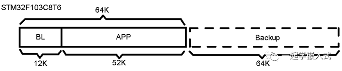
I accidentally discovered that the STM32F103C8T6 and RBT6 chips are the same. However, some chips with 64KB of ROM have poor performance or defects, and thus are restricted from use. I tested this, and it was indeed the case.
However, using the latter 64K ROM has prerequisites; it must first be verified for defects. If it is good, we temporarily store it for verification before writing to the APP area; if it is defective, we write it directly to the APP area during firmware transmission (this method has worked for me many times without discovering defects in the latter 64K).
The above method introduced by Zhenan is a kind of “trick operation” that inherently carries some risk. ST officially states that it does not guarantee the quality of the latter 64K ROM, so it should be used cautiously.
Wireless Programming within 10 Meters
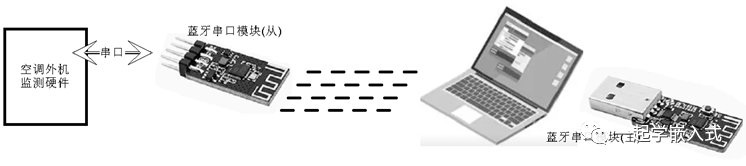
This “wireless programming” originated from one of my IoT projects, which involved monitoring the operational status of the air conditioner’s outdoor unit. As you know, installing the outdoor unit of an air conditioner is not something just anyone can do; it is either on the roof or in a window. This presents significant challenges for hardware upgrades of embedded programs.
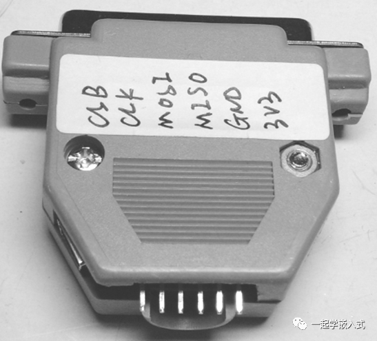
Therefore, I implemented the “wireless programming” function, which is essentially an extension of serial BL application, as shown in the figure, using a Bluetooth serial module to achieve “wireless programming”.
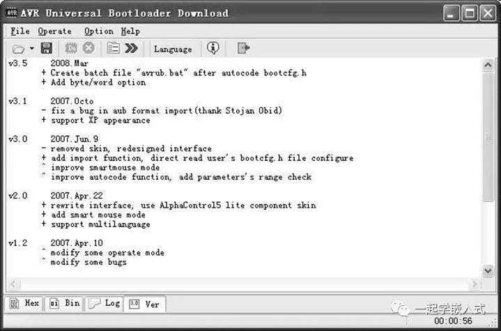
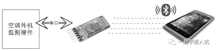
“Wireless programming is indeed powerful, but you still have to carry a computer, which is not very convenient.” Indeed! Do you remember that I mentioned the AVRUBD communication protocol earlier? Its host computer software has a mobile version. So as long as we have a phone, we can perform “wireless programming,” as shown, with the phone connecting to the Bluetooth serial module to achieve “phone wireless programming”.
“Which app? Quickly tell me the name,” don’t rush; the Android version of the Bluetooth serial assistant is shown below, and it is currently transmitting firmware.
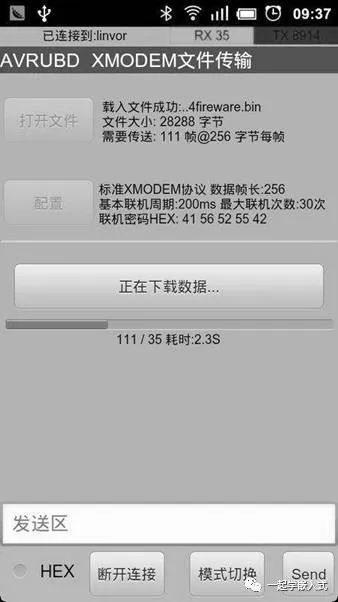
AVRUBD is actually an improvement of the Xmodem protocol; we will discuss this in detail in a dedicated article.
Distributed Programming of BL
We know that the core function of BL is essentially program programming. Have you ever encountered a more complex situation, as shown in the figure, where a system (product) has multiple components that need firmware programming?
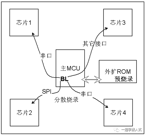
This situation is possible. A typical complex system architecture includes a main MCU + CPLD + communication coprocessor + acquisition coprocessor. During mass production of such products, programming is very tedious. First, multiple firmwares need to be maintained, and then each component must be programmed individually, which may also involve different programming methods. Therefore, I introduced a mechanism called “distributed programming of BL.”
First, we assemble all the firmwares into a large firmware (concatenating the data sequentially) and pre-program this large firmware into external ROM, such as SPI Flash; then we pre-program the main MCU with the BL; and then perform SMT soldering.
Once the PCBA is produced, as soon as it is powered on for the first time, the BL will read the large firmware from the external ROM and separate each small firmware, programming them into the respective components through their corresponding interfaces. Coupled with the test commands from the test fixture, it directly performs self-checking.
Doing this makes mass production highly efficient. Of course, developing this BL will also have some difficulty, with the biggest problem possibly being the implementation of programming interfaces for each component (some components have relatively complex programming protocols, such as STM32’s SWD or ESP8266’s SLIP).
There is no best BL, only the most suitable one for oneself. Generally speaking, we do not design BL to be very complicated; in principle, it should be as short and concise as possible to save more ROM space for the APP area. After all, the APP is the protagonist of the product.
Unconventional BL
Bootpatcher
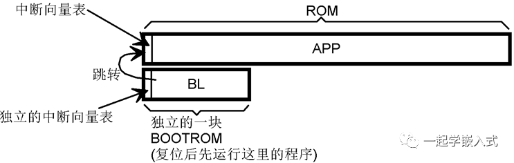
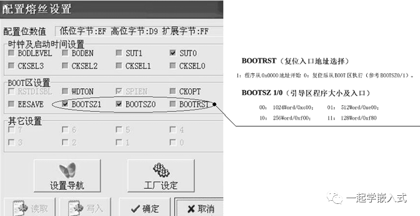
Let me ask everyone a question: “Does the Bootloader have to be located before the APP area in ROM?” Clearly, it does not; AVR is the best example. But what if we limit it to STM32? It seems so. The power-on reset must start running from the 0X08000000 position, and the BL must run before the APP.
In some special cases, if the APP must be placed at the 0X08000000 position, is there still a way to implement serial programming with BL? Please note that when the APP is running, it cannot IAP its own program memory (that is, it cannot erase its own memory to reprogram new firmware). Please see the figure; the BL located after the APP is referred to as Bootpatcher.
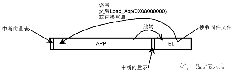
When the APP wants to reprogram itself, it can directly jump to the subsequent BL; once the BL runs, it starts receiving firmware files, temporarily stores them, verifies them, and then writes the firmware to the previous APP area. It then jumps to 0X08000000 or directly restarts. Thus, the new APP will run.
This BL located behind the APP is referred to as Bootpatcher (meaning launch patch). However, this method carries risks; if the APP area programming fails, the product becomes a brick. Therefore, this method is generally not used.
APP Reprogramming BL
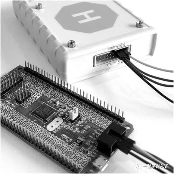
Previously, we discussed BL programming the APP; but what if the BL needs upgrading? Using JLINK is one option. Correct, but there is a more direct method, as shown, where the APP programs the BL area.
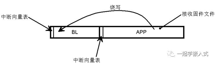
This is a reverse-thinking approach; we implement receiving firmware files in the APP program, temporarily store them, and then program them into the BL area. This method is similar to Bootpatcher and carries certain risks, but generally, it is not problematic.
Conclusion
OK, this series of articles provides a thorough analysis of BL, aiming to be both insightful and comprehensive, covering basic principles, practical implementations, and some knowledge extensions. I hope it will inspire everyone to apply this knowledge in their actual work.
Author/Source: Learn Embedded Together