UART, SPI, and I2C are very common serial communication methods in embedded development. The underlying communication principles of these protocols are not difficult, but many beginners struggle to learn them.
Today, I will share some common underlying data transmission principles of these communication methods.
UART Serial Communication
UART: Universal Asynchronous Receiver-Transmitter. The UART serial port is the most common type of serial communication. Below is an animation showing the connection of the serial port to a host computer and the application of RS232.
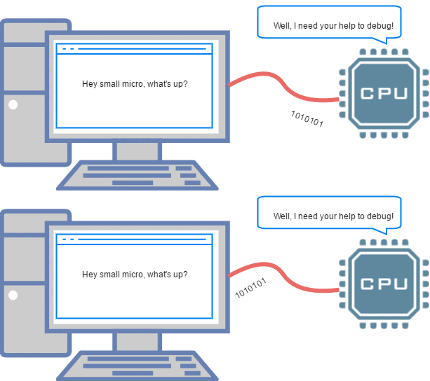
▲ Debugging MCU via UART on PC
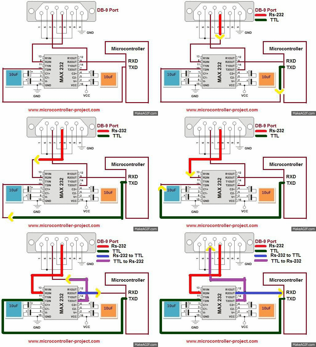
▲ RS-232 communication with MCU via level conversion chip
SPI Serial Communication
SPI: Serial Peripheral Interface. SPI is a common serial synchronous communication protocol with a wide range of applications.
Below is the timing diagram for SPI data transmission:
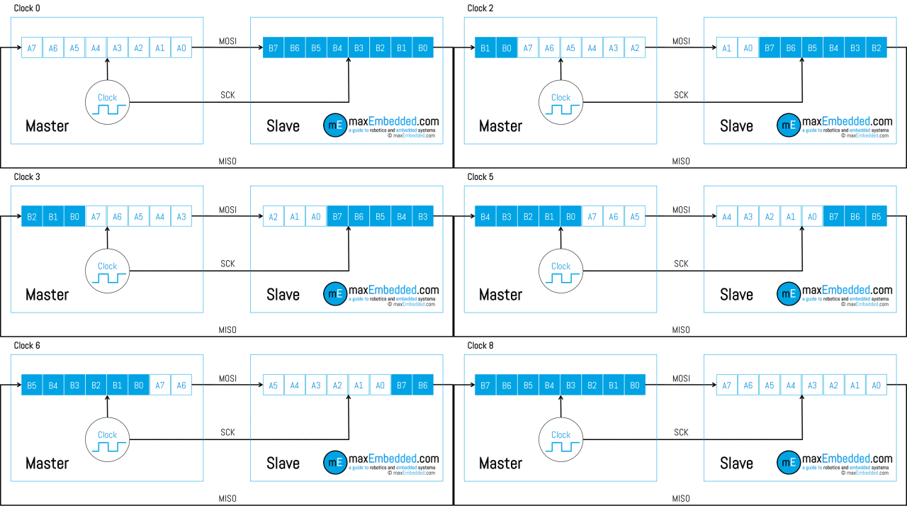
▲ SPI Data Transmission (1)

▲ SPI Data Transmission (2)
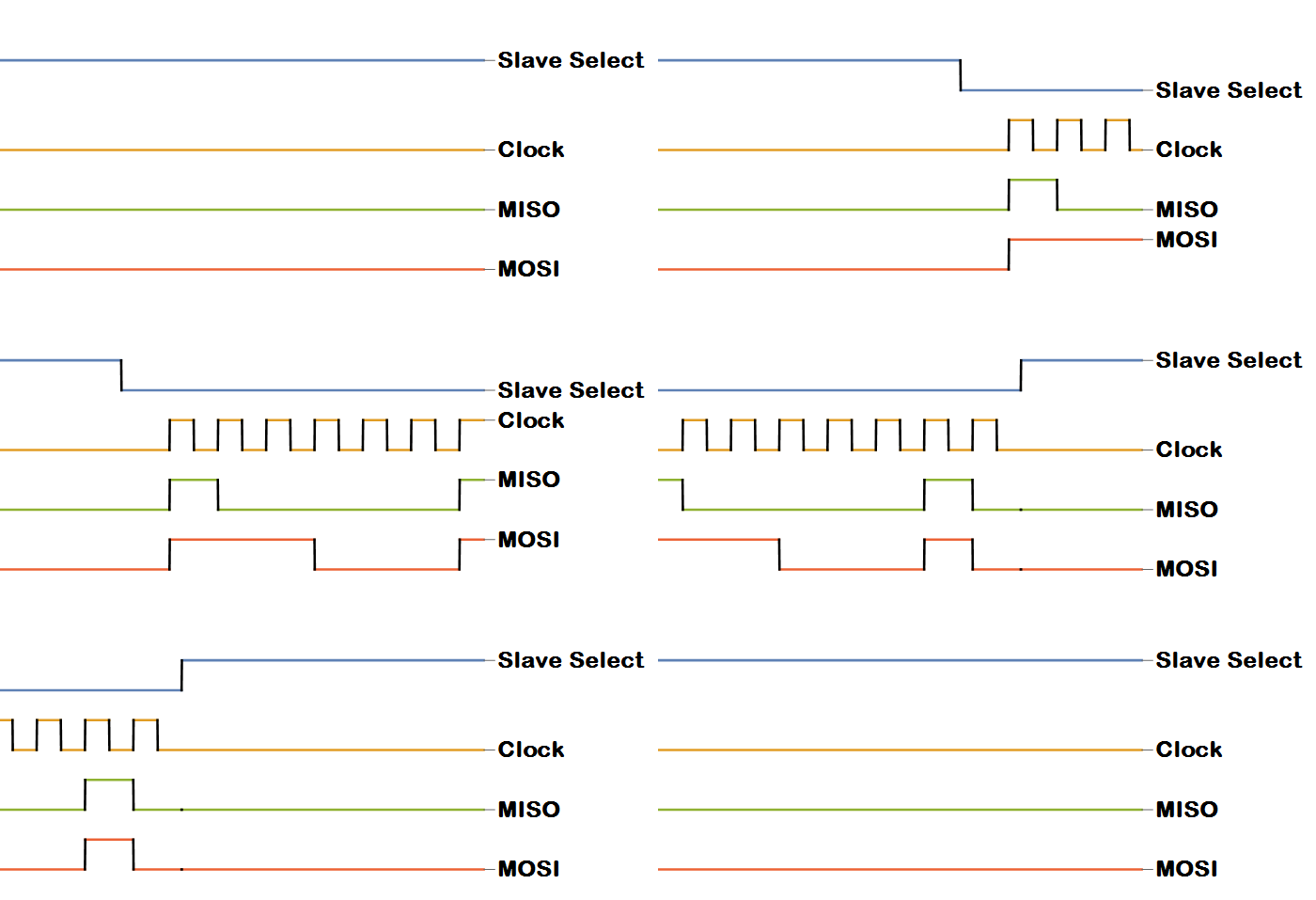
▲ SPI Timing Signals
I2C Communication
I²C: Inter-Integrated Circuit, literally meaning between integrated circuits, is abbreviated as I²C Bus. I²C primarily distinguishes slave devices through addressing, and its communication principle is relatively simple.
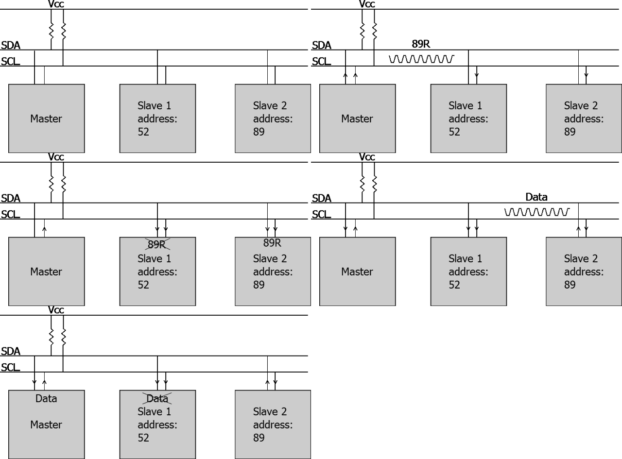
▲ I2C Bus and Addressing Method
Infrared Remote Control
Infrared remote control is quite common in our daily lives; most household remote controls are infrared. Infrared remote control communicates by controlling pulse width (the duration of high and low levels) and establishes a communication link through infrared wireless signals (it cannot work if blocked, but can reflect).
Infrared remote control is quite common in our daily lives; most household remote controls are infrared. Infrared remote control communicates by controlling pulse width (the duration of high and low levels) and establishes a communication link through infrared wireless signals (it cannot work if blocked, but can reflect).

▲ Infrared control signals are also a type of serial communication signal
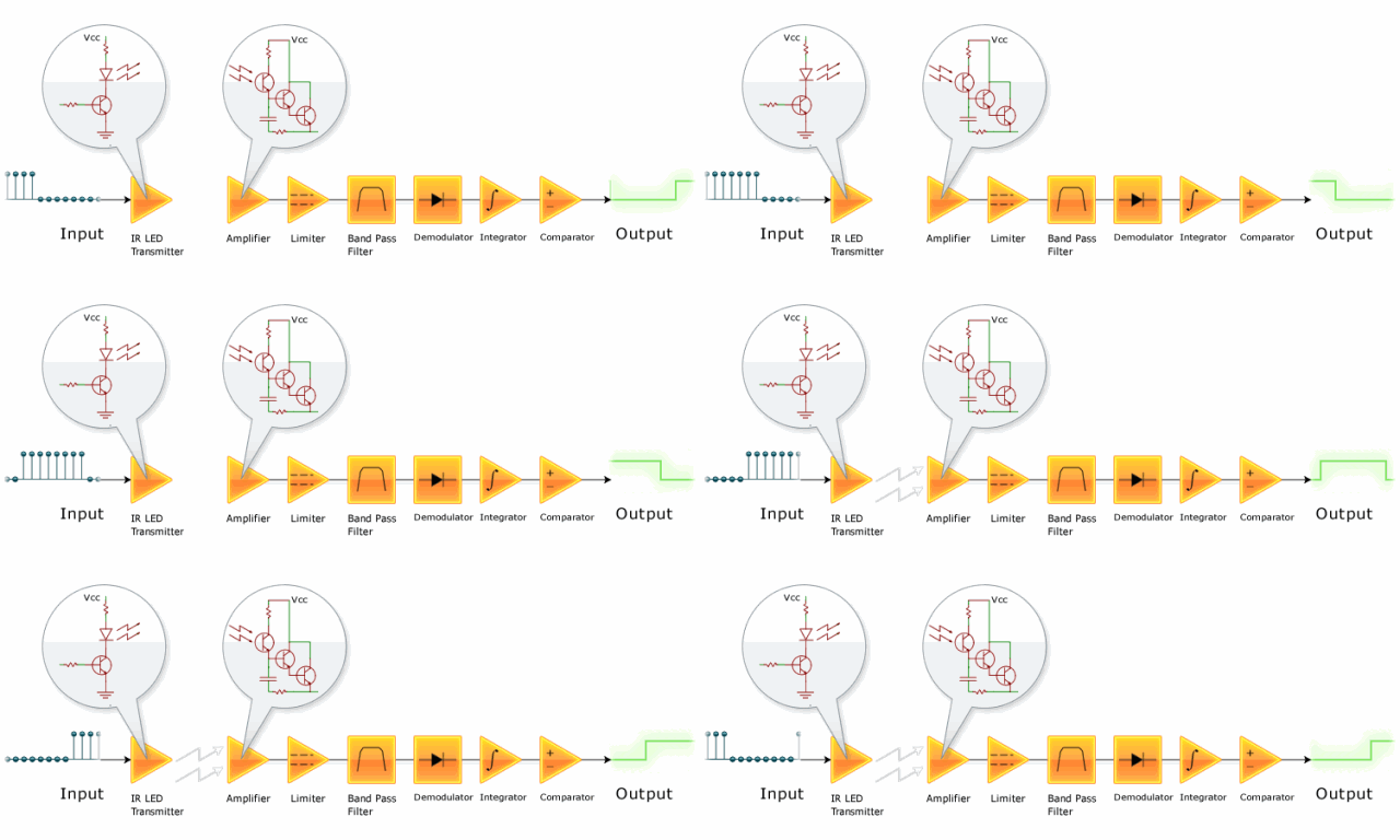
▲ Infrared signal receiving and amplification shaping circuit
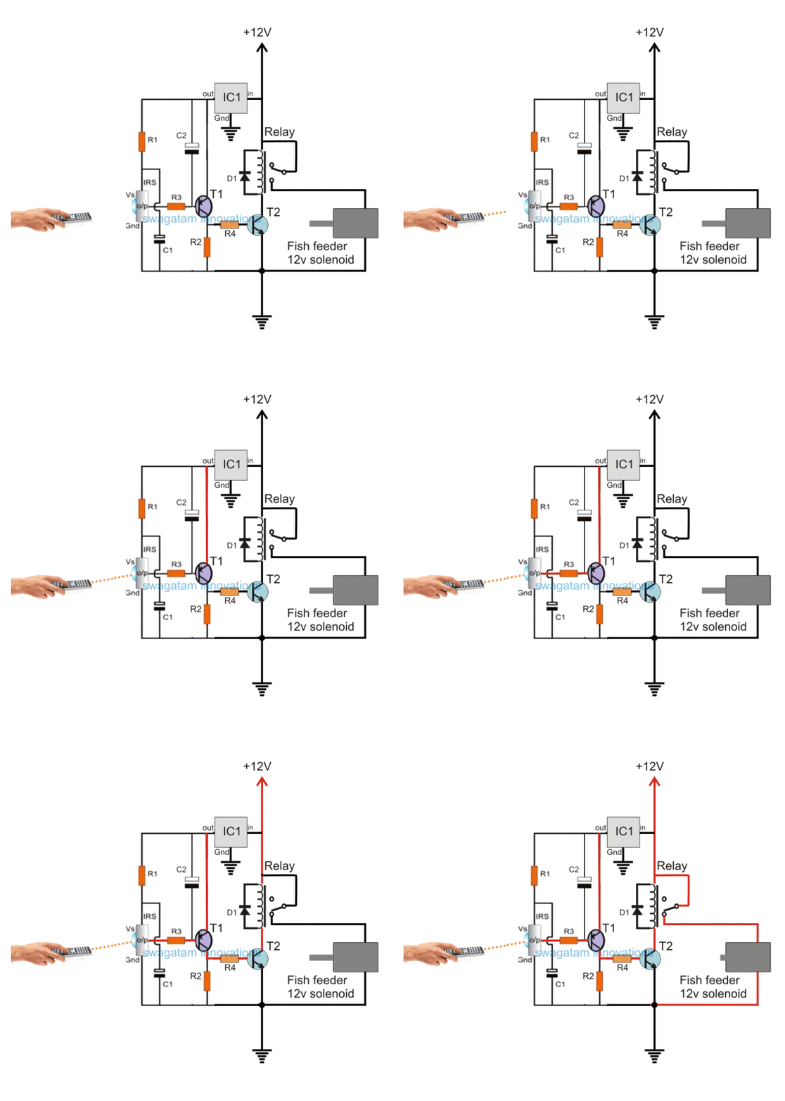
▲ A circuit using an infrared receiver phototransistor to control a relay for fish feeding
Serial to Parallel Conversion Circuit
Serial to Parallel Conversion refers to converting serial data into parallel data. Serial data is transmitted bit by bit under clock control, and when it accumulates to a full byte (8 bits), it becomes parallel data. There are many off-the-shelf chips for this type of converter, and the principle is quite simple.
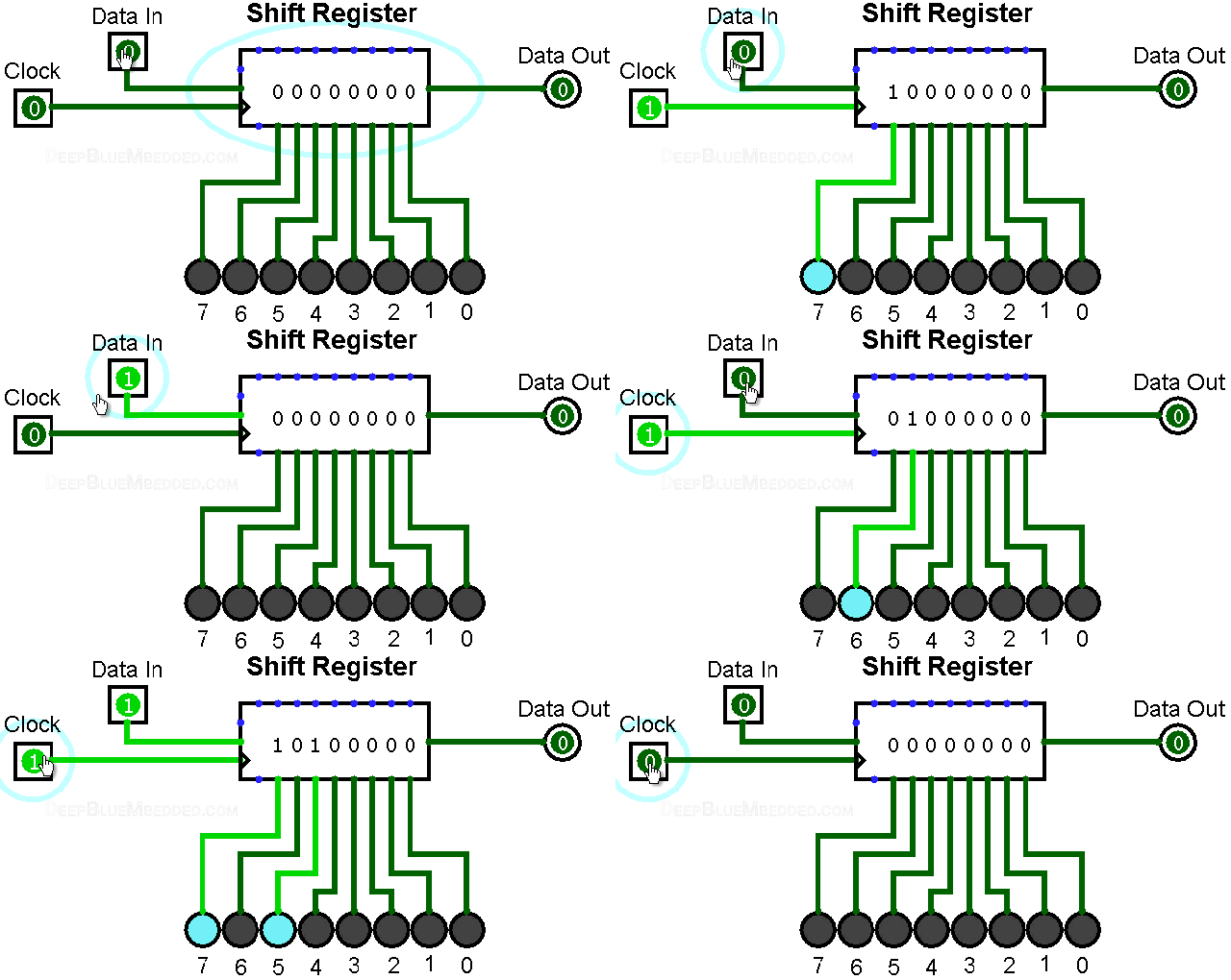
▲ Serial input, parallel output shift register

▲ Shift register composed of eight D flip-flops
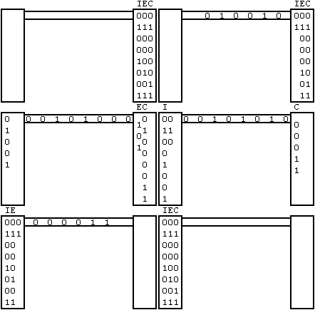
▲ Serial transmission schematic
Others
Here are some other principles of serial transmission (waveforms):
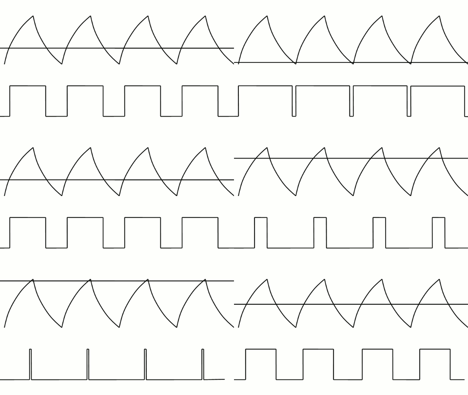
▲ PWM control of LED brightness
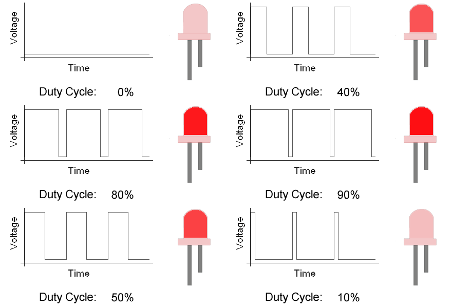
▲ PWM control of LED brightness
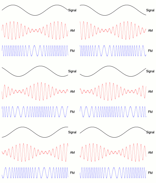
▲ Amplitude and frequency modulation signals
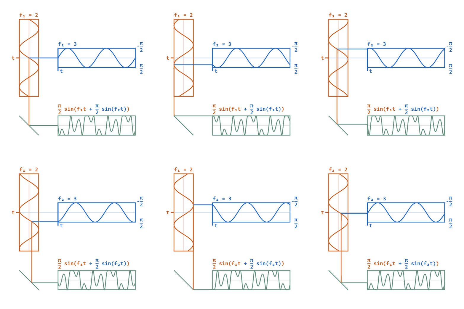
▲ Phase modulation signal
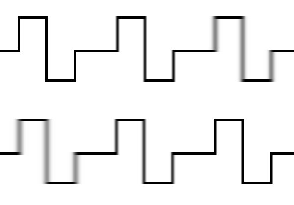
▲ Square wave edge jitter waveform
Source: https://blog.csdn.net/an520
—— The End ——Previous Recommendations:
Why do old electricians pretend to search for faults for two hours when it only takes one minute? Only those who understand can see through it.
How to design a circuit for RS485 direction switching? Introduction of 5 schemes and analysis of their advantages and disadvantages!
How to write your own instructions using S7-200 SMART? It can make me look impressive!
[Case Study] A guide to mastering maintenance techniques for marine Vacon frequency converters!
The little-known history of “Chinese core” pressure sensors!
Share 💬 Like 👍 View ❤️
Support quality content with a “three-link” action!
Every little bit counts, keep learning👇 ClickRead the original text for more valuable content