For general-purpose MCU chips, the CPU operating frequency ranges from 100 to 300 MHz, while the frequency of typical crystals (xtals) is usually in the tens of MHz range. Therefore, MCUs typically use a PLL module to multiply the frequency to the hundreds of MHz range.Similarly, taking the STM32F10xxx series as an example, let’s examine the considerations for clock design in general-purpose MCU chips.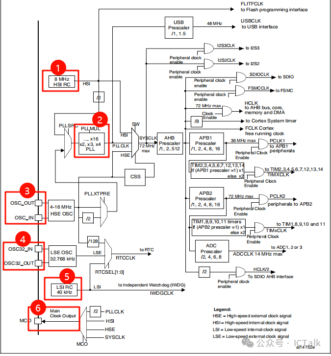 As shown in the figure above,
- the chip has two external input clocks, labeled 3 and 4, where 3 is a standard XTAL with a frequency of 4-16 MHz, and 4 is expected to be a 32.768 KHz XTAL.
- The chip has two internal RC oscillators, labeled 1 and 5, where 1 oscillates at 8 MHz and 5 oscillates at 40 KHz.
- 2 is the PLL module, which outputs a clock of 72 MHz. The PLL input can be the internal 8 MHz oscillator or an external high-frequency XTAL.
- 6 is the clock output pin of the chip.
To simplify, the basic clock architecture is as follows: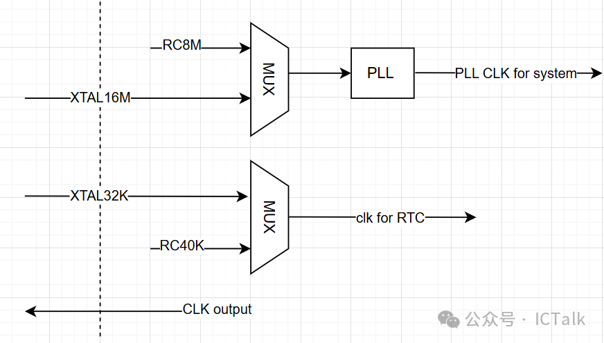 In summary:
- Generally, if there is a need for accurate timing, such as displaying the year, month, day, and time, an external 32K XTAL oscillator should be added. If only general timer counting or system wake-up timing is required, the internal RC 40K can be used directly, eliminating the need for the 32K XTAL oscillator.
- Similarly, for the 16M XTAL oscillator, if the chip does not have high precision requirements for the clock, it can also be omitted, and the internal RC 8 MHz clock can be used to generate a high-frequency clock through the PLL.
- The internal PLL clock can generally be bypassed and is used in low-power scenarios or when clock frequency requirements are not high.
- The chip’s output clock can be used to supply some peripheral circuits or other chips, which can be very useful in certain scenarios.
Done!