3. BCM System Composition and Control Principles
The Controller Area Network (CAN), Local Interconnect Network (LIN), and FlexRay are commonly used automotive buses.
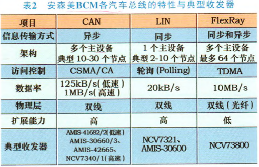
The CAN bus is a serial multi-master controller real-time control local area network bus, with synchronous information transmission. The physical layer is a single wire; the architecture consists of one master device and 2 to 10 slave devices. The LIN information transmission method is asynchronous, with a physical layer of two wires; the architecture consists of multiple master devices and 10 to 300 slave devices. Both have high scalability. The CAN data rate is 20kB/s, while the LIN data rate can reach up to 1MB/s at high speed and 125kB/s at low speed. The low-speed CAN bus can increase the transmission distance of the bus, improve anti-interference capability, and reduce hardware costs.
The control targets are numerous, and the real-time requirements for information transmission are not high, mainly involving low-speed motors, solenoid valves, various lamps, and switch devices. Communication via the LIN bus is conducted by the main control module, door control module, central locking module, and voice alarm module, which are low-speed systems with lower bandwidth and complexity requirements, such as switch-type loads or position-type system controls.
Automotive wipers and fans in air circulation systems are large inductive loads. To reduce the impact of strong back electromotive force on the system power supply during switching, pulse width modulation (PWM) is used to achieve soft start, which also protects the electrical devices and enhances the vehicle’s electromagnetic compatibility. PWM adjusts the output duty cycle (pulse width) of the output (which is usually a fixed frequency switching signal) to control the lighting on and off time to achieve brightness adjustment.
Figure 4 shows the functional principle block diagram of the Body Control Module (BCM) for the CAN/LIN hybrid bus.
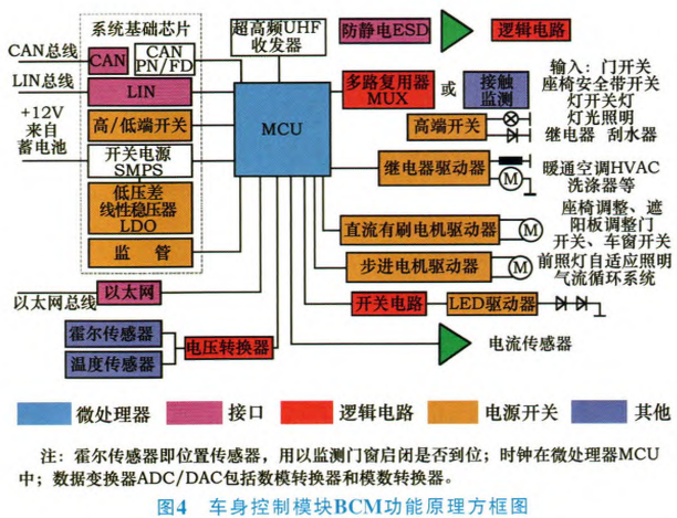
The MCU (Microcontroller Unit) is the core of the entire body control module, working like a gateway for the bus and network interface, monitoring and controlling various load drivers in the body controller according to protocol requirements.
It reacts to corresponding inputs and makes corresponding output controls based on pre-defined logical planning, serving as the system’s core. Its features allow for signal sharing, where one input signal enables multiple control functions of the body through the BCM. There is personalized programming, allowing the driver to easily change certain control functions related to the BCM.
It is also paralleled with transient voltage suppressors to effectively suppress high voltage pulses of up to +45V that occur when the instantaneous power load drops (such as during engine startup); this includes unstable power noise—this indicator must comply with the overvoltage testing specifications in the automotive 12V power system IS016750-2-2003 section 4.6.
3.1 Input Control
Due to objective factors such as load capacity and anti-interference capability, many signals cannot be directly applied to the MCU; appropriate input circuits are required to isolate and condition the signals for safe and reliable transmission to the MCU.
The following discusses two types of signals: switch signals and pulse signals.
1) Input of switch signals.
This involves determining whether a switch action exists by connecting the system to the positive power supply (+B) or grounding (GND). There are only two states for switch input: high level and grounded.
For example, with the ignition switch, when the switch is on, the BCM receives a signal of +B; when the ignition switch is off, the BCM signal becomes floating. Similarly, for the door contact switch, when the door is open, the switch connects, and the signal to the BCM is grounded; when the door is closed, the signal to the BCM will float. This is precisely why there is a need for signal voltage amplitude.
2) Input of pulse signals.
Pulse signals can be seen as periodic switch signals, such as the data input signal of a decoder, airbag signals, vehicle speed signals, etc. All electronic components that have signal interaction must have hardware and software matching at their interfaces to ensure reliable system operation.
The internal processing circuit of the BCM has its own stable logic level state. External inputs attempt to change this logic state, which is ultimately recognized by the BCM. Generally, a reliable high level requires greater than 0.7V, while a reliable low level requires less than 0.2V. Input levels between these two may lead to logical misjudgment by the MCU. Excessively high contact resistance of the switch may cause variations in the input signal.
Communication Interface. Data exchange between various independent electronic control modules in the vehicle and remote submodules of the body control module must go through communication interfaces. The high-speed CAN (according to ISO 119898, with a rate of up to 1MB/s) is a dual-wire fault-tolerant differential bus. It has a wide common-mode range input and differential signal technology, serving as the main automotive bus type interconnecting various electronic modules in the vehicle. The LIN bus supports low-speed (20kB/s) single-bus wired networks, addressing communication with remote sub-functions of the infotainment system. Communication detection is achieved through the CAN bus and diagnostic connectors.
A/D Conversion. The detection of information input from sensors (rain, sunlight) or current information (whether the window motor is jammed) is a measurement of voltage analog quantities. If there are small voltage changes, they may be difficult for the MCU to recognize, requiring amplification circuits to boost the signal amplitude.
Radio Frequency Identification (RFID). The most common applications are the remote unlocking system and the engine anti-theft lock system. Design manufacturers provide LF ICs for encrypted communication with ignition switch keys (engine anti-theft lock system) and UHF (frequency below 1 GHz) transceivers for remote communication, featuring ultra-low power consumption (static current less than 30μA, driving current range between 100-300mA) to lock/unlock vehicle doors and alarm systems.
3.2 Output Control
The main types of load drivers in the BCM are various lamps and relays. Power switches and drivers for controlling external lights are installed directly on the controller. Relays are used to power larger loads or other electronic modules. The battery charging and discharging of the entire vehicle and load management of other ECUs are achieved through current monitoring functions.
Due to inherent limitations in load capacity, many loads cannot be directly controlled by the I/O of the MCU, requiring appropriate output interface circuits to implement BCM control over external loads.
The main output controls of the BCM are categorized into the following three types.
1) Relay control output: The BCM controls external relays to activate them.
2) Low-power load output: The BCM directly controls warning lights, indicator lights, and smaller power lamps (such as dome lights, seat belt indicator lights, step lights, etc.).
3) High-power load output: Directly controls external high-power loads, such as power window and central locking control outputs, specifically for central door locking functions.
The functions can be listed as follows: door switches, airbags, combination instruments, left and right front door window lifter switches, ignition switches, left and right front door locks, left and right rear door locks, sound alarms (horns, etc.), seat belt unbuckled switch signals, and headlight combinations, etc.
Additionally, the vehicle speed signal input is connected in series in the relay of the central locking system, preventing the doors from being opened while driving to ensure safety.
Regardless of the output method, it is essential to ensure that any part of the entire circuit can withstand the load capacity and provide sufficient margin.
3.3 Power Management
Power management features a linear voltage regulator with sufficiently low static current. This is highly beneficial for the standby state during ignition switch disconnection. It greatly reduces leakage current losses and excessive voltage drop, preventing voltage limits from exceeding during sudden load drops.
Switching power supply field-effect transistors (EFT) improve conversion efficiency and can implement power sequencing through multiple switching power supplies (SMPS). Selecting appropriate input capacitance limits surge currents, achieving soft start and reducing ripple current, which also helps improve electromagnetic interference (EMI) and enhance electromagnetic compatibility. Regulated power supplies can provide excellent overall voltage regulation accuracy, transient response, and simple loop compensation.
Power management also encompasses high and low voltage protection, delayed power-off, and system sleep functions. A high-performance body control module not only has an extremely low static current but also provides a sleep mode (low transmit power, yet high receive sensitivity, low power consumption, and suitable frequency range, etc.). For instance, ON Semiconductor’s ON-53480 high-frequency transceiver has a static current as low as 1μA, signal level of 10dBm, receive sensitivity below -100dBm, operating current of 10mA, and frequency range of 280-343MHz, equipped with wake-up and sleep detection functions.
Protection of power circuits (such as surge current protection, drop protection) is essential to cope with the harsh operating environment of automobiles, ensuring the system operates safely and stably. The corresponding standards are IS011542, IS07637-2, etc.
3.4 High-Frequency Receiving Circuit
The function of the remote control receiving circuit is to receive the high-frequency modulated signal sent by the remote control transmitter and then demodulate the data for processing and judgment by the BCM. Commonly used modulation/demodulation high-frequency receiving circuits can be categorized into super-regenerative and superheterodyne types.
The advantage of the superheterodyne receiver is frequency stability, good anti-interference capability, and stable performance when combined with microcontrollers. However, its sensitivity is lower than that of the super-regenerative receiver, and its price is much higher.
The high-frequency receiving circuit determines the effectiveness of remote control reception. In addition to its own performance and the requirements of the remote transmitter, it also needs to adapt to an efficient receiving antenna. Common antennas used by the BCM include rubber antennas, external soft wires, and directly using PCB printed antennas. External antennas and printed antennas generally achieve the best effect when their lengths are 1/2n of the used frequency wavelength, where wavelength λ=c/f (c=speed of light).
ON Semiconductor products offer high-energy efficiency and high-performance electronic devices and controllers, demonstrating outstanding performance in automotive electronics technology. Table 2 presents a comparison of the characteristics and typical transceivers of various automotive buses from ON Semiconductor’s BCM, available on their website.
(Source: Image and text from the internet)
Click the mini-program below to see more repair cases