

The industrial control system is the “nerve center” of modern industry, and its importance spans multiple dimensions including the operation of critical infrastructure, economic development, and national security. Industrial control systems have evolved from mere production tools to important symbols of national infrastructure security, economic competitiveness, and technological strength. Their significance is not only reflected in the physical control of equipment but also permeates strategic dimensions such as cybersecurity, energy security, and the autonomy of the industrial chain. Under the strategies of “smart manufacturing” and “digital China,” strengthening the technological innovation and security assurance of industrial control systems is an essential path to promote high-quality industrial development and maintain national strategic security.


Overall Functionality

The testing and verification of industrial control systems require the use of hardware-in-the-loop simulation technology to simulate the on-site operating environment. By conducting functional tests and stress tests on industrial control systems, potential program vulnerabilities can be identified in advance to avoid equipment loss of control due to control logic errors. Through comprehensive testing that simulates the entire production environment, hardware compatibility issues or software conflicts can be exposed early. The testing and verification of industrial control systems need to establish a four-dimensional verification system covering “function, performance, safety, and reliability,” ensuring that industrial control systems can meet production demands in complex industrial environments through a testing process that covers the entire design, development, and deployment cycle.
To meet the testing and verification needs of industrial control systems in different industries, our company has launched a solution for the simulation testing environment of industrial control systems.
The overall functionality of the industrial control system simulation testing environment includes:
-
Simulating normal and abnormal conditions in the on-site operating environment through simulated sensor signals;
-
Achieving full system simulation through model simulation of actuators that are inconvenient to deploy in the laboratory, enabling system functionality and performance testing;
-
Supporting distributed testing, allowing for full-scale testing and verification according to the actual deployment nodes of the industrial control system;
-
Simulating various physical layer faults that may occur in the on-site operating environment through a fault injection unit to test the emergency response mechanisms of the industrial control system;
-
Simulating the actual workflow of the industrial control system to verify the collaborative working ability between distributed controllers.

Hardware Architecture
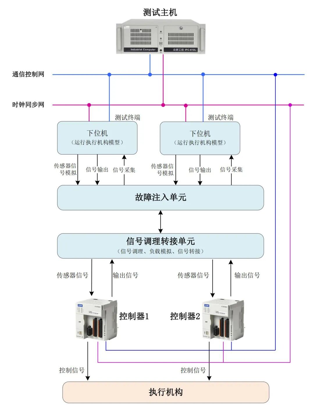
The hardware architecture of the industrial control system simulation testing environment is shown in the figure below, and its main principles are as follows:
-
The testing host, testing terminals, and the control system under test achieve data exchange through a communication control network and synchronize clocks through a clock synchronization network;
-
The testing host controls multiple testing terminals, installing various interface boards to simulate signals from various on-site sensors and collect signals output by the controller;
-
The testing terminal loads actuator models, driving the models based on the collected controller output signals, and can convert model outputs into actual signals fed back to the controller;
-
Simulating physical layer faults in the controller’s input and output signals through a fault injection unit;
-
Implementing signal conditioning, load simulation, and signal switching through a signal conditioning interface unit.
Functional Architecture
System Principle Diagram
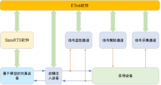
The implementation principle of the industrial control system simulation testing environment is shown in the figure below. The system functionality relies on our company’s testing system integration development environment ETest and real-time simulation software SimuRTS. Among them, SimuRTS is responsible for loading models, supplemented by interface boards to implement model-based simulation devices; ETest is responsible for the program control, signal monitoring, signal excitation, and signal acquisition of the fault injection devices, as well as the functional scheduling of SimuRTS based on API.
System Layout
System layout diagram
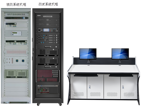
The overall reference layout of the industrial control system simulation testing environment is shown in the figure below. The testing host, testing terminals, fault injection devices, and signal conditioning interface devices are installed in one cabinet; another cabinet is used to place the control system under test; the operation platform provides a workspace for testing personnel, equipped with monitors and input devices.
Software Platform – ETest

Main Functions
01
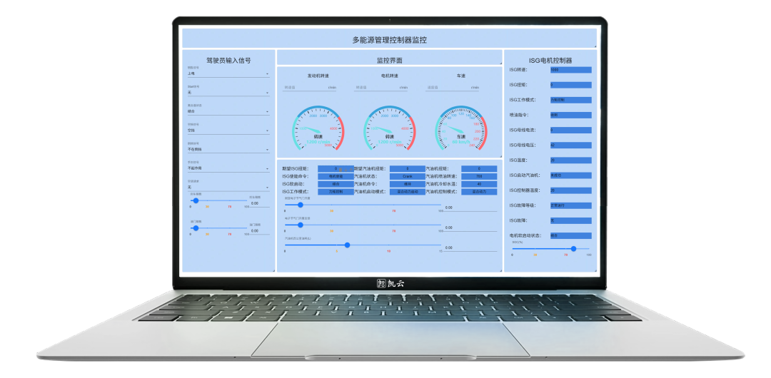
The testing system integration development environment ETest is mainly used to support the rapid design and development of testing tools for various levels of individual devices, subsystems, and system-level hardware-in-the-loop simulation testing, and can also support the rapid design and development of software for testing devices at all levels. The system provides basic services for describing device interconnection relationships, bus communication protocols, sensor and actuator mapping, and functional logic development, significantly reducing the difficulty of designing and developing various hardware-in-the-loop simulation testing devices, providing an integrated development environment for the development of testing software for equipment in complex interconnection environments.
In this simulation testing environment, ETest mainly provides the following key functions.
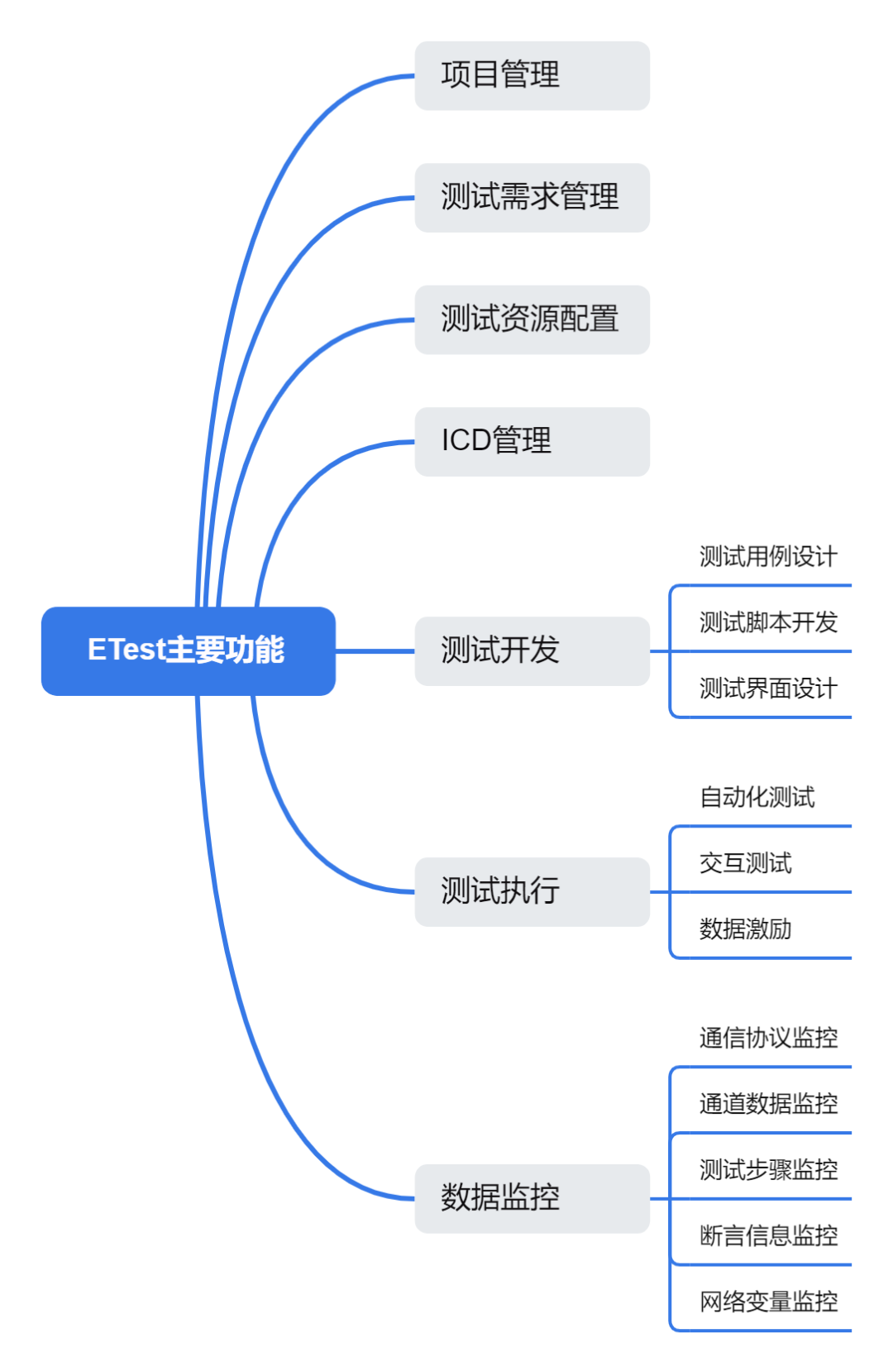
▲ Main software functions
Software Architecture
02
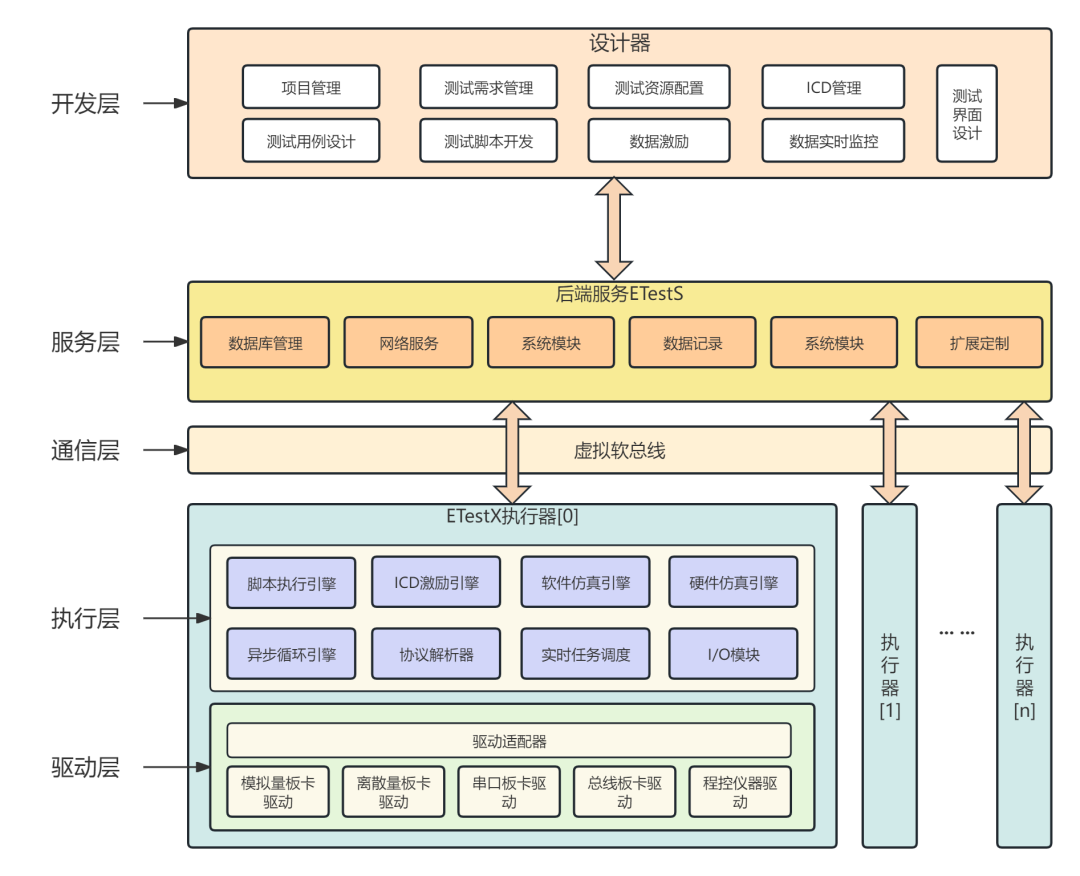
The software architecture of the testing and verification environment is shown in the figure below. The software architecture mainly includes the development layer, service layer, communication layer, execution layer, and driver layer.
▲ Software architecture diagram
1) Development Layer: Provides users with various management and design modules based on the software designer, including project management, testing requirement management, testing resource management, ICD management, test case design, test script development, test interface design, data excitation, and real-time data monitoring.
2) Service Layer: Bridges the upper computer software and actuators based on the backend service ETestS, providing services such as database management, network services, system modules, data recording, and system modules.
3) Communication Layer: Based on virtual soft bus technology, supports the software system to network in any topology, allowing devices to be dynamically added or removed according to actual needs without affecting the normal operation of the entire system.
4) Execution Layer: Based on the EtestX actuator, serving as the testing and verification engine, its main modules and their functional descriptions are as follows:
-
Script Execution Engine: Executes the test scripts issued by the upper computer, receives control commands for script execution (start, stop) from the upper computer, and feeds back the script execution status;
-
ICD Excitation Engine: Packages the data to be sent based on the ICD file, and according to the data excitation strategy issued by the upper computer, hands the data to the I/O module for processing;
-
Software Simulation Engine: Executes the FMU model according to the simulation configuration, ensuring the timeliness and correctness of model execution, receives simulation control commands (start, stop) from the upper computer, and feeds back the model execution status;
-
Hardware Simulation Engine: Compiles the FPGA algorithm according to the simulation configuration and sends it to the FPGA chip, receiving simulation control commands (start, stop) from the upper computer, and feeding back the FPGA algorithm execution status;
-
Asynchronous Loop Engine: Supports multi-node, multi-model, multi-channel asynchronous execution, supporting distributed joint simulation scenarios of multi-source heterogeneous models;
-
Protocol Parser: Parses the data received at the summary interface based on the ICD;
-
Real-time Task Scheduling: Compares the current task priority with the interrupt thread priority in the interrupt service routine entry function based on the priority of real-time tasks, ensuring that high-priority real-time tasks are not disturbed and that high-priority interrupts can respond immediately;
-
I/O Module: Receives the data transmission parameters passed by the script, parses them, and hands them over to the hardware driver for processing to achieve data transmission.
5) Driver Layer: Based on the driver adapter, it abstracts and encapsulates hardware drivers, shielding programming personnel from the differences in hardware driver interfaces.
Software Interface Layout
03
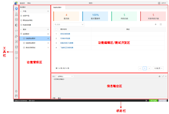
The overall interface layout of the testing and verification environment software is shown in the figure below.

▲ Software interface layout diagram
The software interface layout mainly includes the toolbar, function management area, function editing area/testing development area, information output area, and status bar.
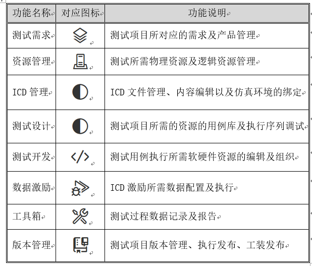
1) Toolbar: The toolbar provides a series of functional entry points, as shown in the table below.
2) Function Management Area: After clicking a functional button on the toolbar, a tree structure management area will be displayed in the function management area, allowing for the creation and deletion of functional elements in the tree structure.
3) Function Editing Area/Testing Development Area: After clicking a functional element in the tree structure of the function management area, the function editing area will be displayed in this area. For testing development functions, the testing script development area will be displayed in this area.
4) Information Output Area: Outputs the status information of the test execution, as well as the print information intended to be output in the test script.
5) Status Bar: Provides information such as Python version, project error/warning information, lower machine connection status, and execution control.
Software Platform – SimuRTS
Main Functions
01
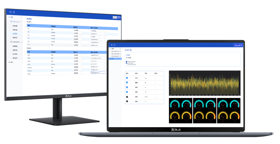
SimuRTS is a real-time simulation software that meets the needs of high-timeliness application scenarios such as rapid control prototype verification, hardware-in-the-loop simulation, and automated testing. SimuRTS serves as a replacement for similar foreign software such as VeriStand, dSPACE, and SpeedGoat, and is widely used in industries such as aerospace, weaponry, industrial control, automotive electronics, and instrumentation. SimuRTS supports both hardware real-time simulation and software hard real-time simulation functions. The hardware real-time simulation function requires SimuRTS to load model algorithms into the FPGA of the simulation hardware device for operation, achieving microsecond-level real-time simulation. The software real-time simulation function relies on a real-time operating system to achieve millisecond-level real-time simulation.
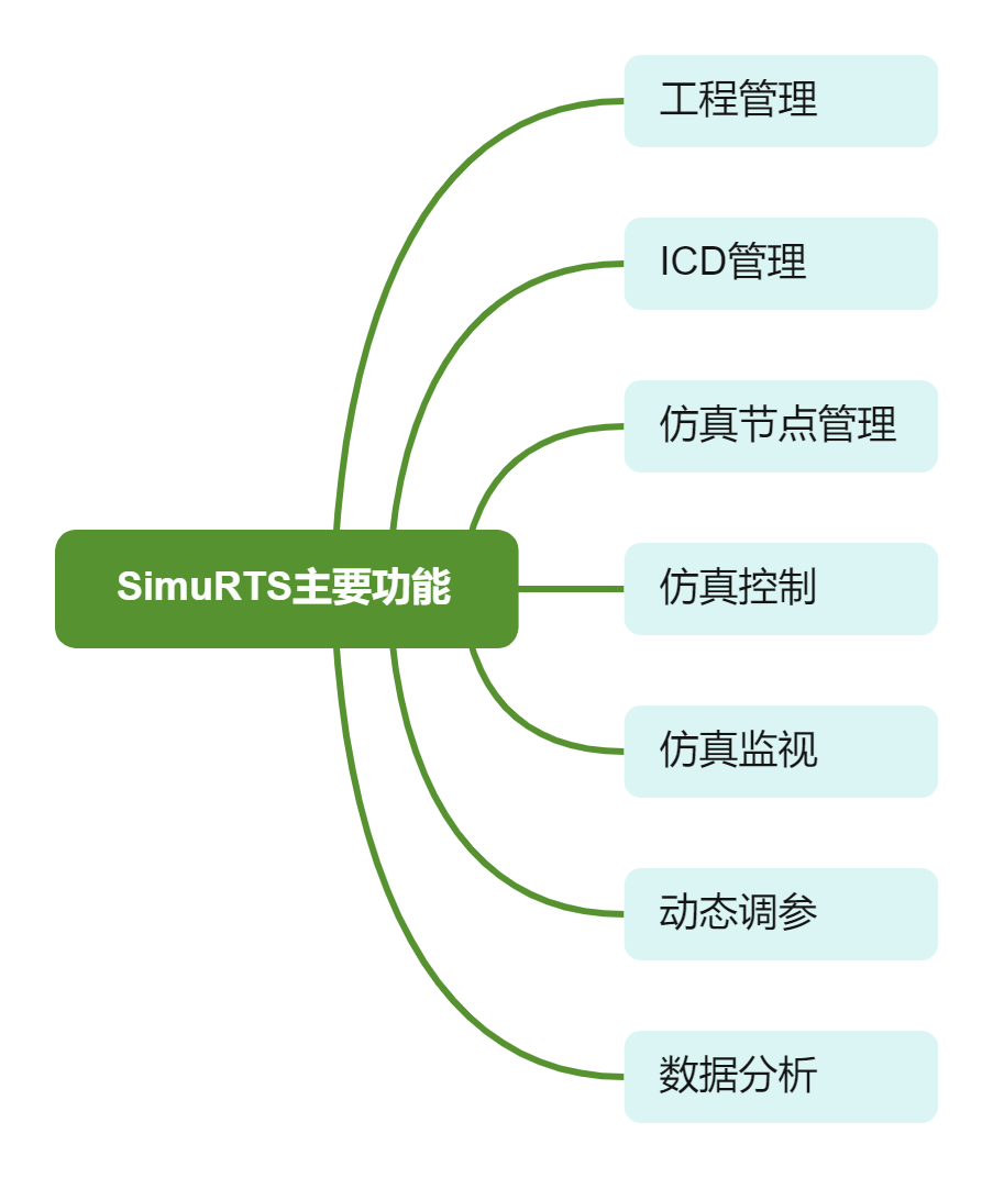
In this simulation testing environment, SimuRTS mainly provides the following key functions.
▲ Main software functions
Software Architecture
02
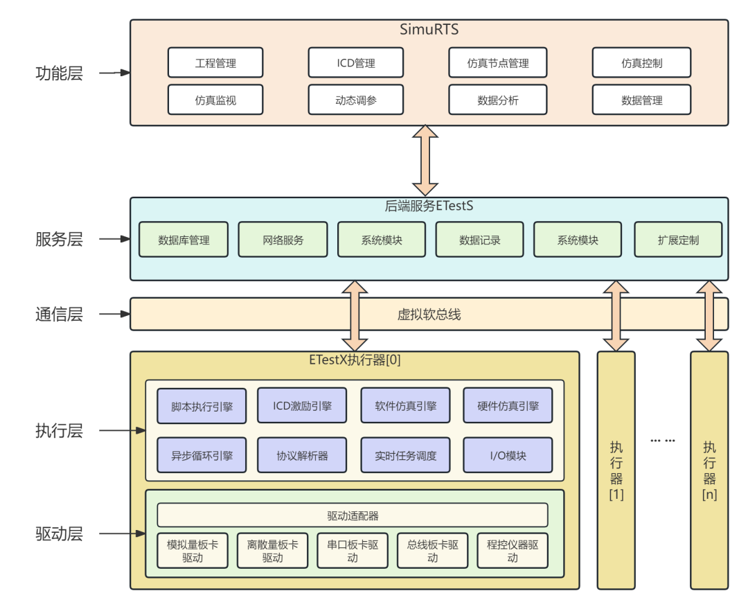
The software architecture of the distributed joint simulation system is shown in the figure below. The software architecture mainly includes the functional layer, service layer, communication layer, execution layer, and driver layer.
▲ Software architecture diagram
1) Functional Layer: Provides users with various functional modules, including project management, ICD management, simulation node management, simulation control, simulation monitoring, dynamic parameter adjustment, data analysis, and data management.
2) Service Layer: Bridges the upper computer software and actuators based on the backend service ETestS, providing services such as database management, network services, system modules, data recording, and system modules.
3) Communication Layer: Based on virtual soft bus technology, supports the software system to network in any topology, allowing devices to be dynamically added or removed according to actual needs without affecting the normal operation of the entire system.
4) Execution Layer: Based on the EtestX actuator, serving as the testing and verification engine, its main modules and their functional descriptions are as follows:
-
Script Execution Engine: Executes the test scripts issued by the upper computer, receives control commands for script execution (start, stop) from the upper computer, and feeds back the script execution status;
-
ICD Excitation Engine: Packages the data to be sent based on the ICD file, and according to the data excitation strategy issued by the upper computer, hands the data to the I/O module for processing;
-
Software Simulation Engine: Executes the FMU model according to the simulation configuration, ensuring the timeliness and correctness of model execution, receives simulation control commands (start, stop) from the upper computer, and feeds back the model execution status;
-
Hardware Simulation Engine: Compiles the FPGA algorithm according to the simulation configuration and sends it to the FPGA chip, receiving simulation control commands (start, stop) from the upper computer, and feeding back the FPGA algorithm execution status;
-
Asynchronous Loop Engine: Supports multi-node, multi-model, multi-channel asynchronous execution, supporting distributed joint simulation scenarios of multi-source heterogeneous models;
-
Protocol Parser: Parses the data received at the summary interface based on the ICD;
-
Real-time Task Scheduling: Compares the current task priority with the interrupt thread priority in the interrupt service routine entry function based on the priority of real-time tasks, ensuring that high-priority real-time tasks are not disturbed and that high-priority interrupts can respond immediately;
-
I/O Module: Receives the data transmission parameters passed by the script, parses them, and hands them over to the hardware driver for processing to achieve data transmission.
5) Driver Layer: Based on the driver adapter, it abstracts and encapsulates hardware drivers, shielding programming personnel from the differences in hardware driver interfaces.
Software Interface Layout
03
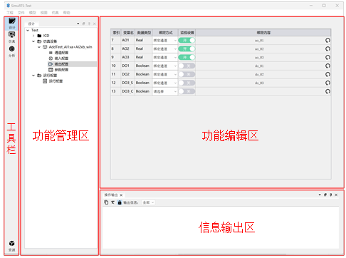
The overall interface layout of the distributed joint simulation system software is shown in the figure below.
▲ Software interface layout diagram
The software interface layout mainly includes the toolbar, function management area, function editing area/testing development area, and information output area.
-
Toolbar: The toolbar provides a series of functional entry points, mainly including: design, simulation, analysis, and resource management.
-
Function Management Area: After clicking a functional button on the toolbar, a tree structure management area will be displayed in the function management area, allowing for the creation and deletion of functional elements in the tree structure.
-
Function Editing Area: After clicking a functional element in the tree structure of the function management area, the function editing area will be displayed in this area.
-
Information Output Area: Outputs status information, warning information, error information, etc., during function execution.
Application Fields

The industrial control system simulation testing environment is suitable for the testing and verification of control systems in various industries, with typical application fields including but not limited to:
-
Testing and verification of distributed control systems in the nuclear industry;
-
Grid control testing of wind power/photovoltaic inverters;
-
Certification testing of safety instrument systems in the petrochemical industry;
-
Testing and verification of flexible production lines in smart manufacturing;
-
Verification of integrated control systems in vehicle networking;
-
Interoperability verification platform for industrial control systems.
The “Industrial Control System Simulation Testing Environment Solution” provided by Kaiyun deeply integrates advanced hardware-in-the-loop simulation technology, distributed testing architecture, and domestic core software platforms (ETest and SimuRTS). This solution aims to build a comprehensive verification system for industrial control systems covering the four dimensions of “function, performance, safety, and reliability,” accurately simulating complex on-site environments and supporting comprehensive testing needs from signal-level simulation, fault injection to full-process system simulation.
This solution can efficiently meet the urgent needs for high-confidence verification of industrial control systems in key fields such as nuclear power, new energy, petrochemicals, smart manufacturing, and vehicle networking, assisting customers in identifying problems early, optimizing performance, ensuring safety throughout the entire lifecycle of product design, development, and deployment, ultimately enhancing the autonomy and core competitiveness of industrial control systems.
Kaiyun Introduction
Kaiyun is a leading domestic supplier of embedded system hardware-in-the-loop simulation and testing basic products, receiving multiple rounds of investment from institutions such as Shenzhen Capital Group and ChinaSoft International. The company is headquartered in Fengtai, Beijing, with branches in Hefei, Xi’an, Changsha, Chengdu, Nanjing, Wuhan, and Mianyang. Its wholly-owned subsidiary, Kaiyun Lianchuang (Beijing) Technology Co., Ltd., is a national high-tech and dual-software certified enterprise, a gazelle enterprise, and a specialized and innovative enterprise.
Core products: Hardware-in-the-loop simulation testing development environment ETest, real-time simulation environment SimuRTS, real-time simulation boards SimuCard, and various testing devices.
Main customers: Aerospace, nuclear industry, electronic equipment, weapons and ships, rail transit, automotive electronics, and higher education institutions.
Consultation Hotline: 4008299000