When performing IoT analysis, accessing the device’s UART interface for debugging is a common operation.
UART generally includes at least four pins: the common ground pin GND, the power pin VCC, the output pin TXD, and the receive pin RXD. We need to use three of these pins: TXD, RXD, and GND.
If you find the UART, you can use SecureCRTPortable to access the router’s control shell on your PC.
Some industry friends might wonder if it’s necessary to write an article about locating a UART. What if the UART has been tampered with by the manufacturer and cannot input or display data? This is what I want to share with you today.
Step 1: Locating the UART Pins
Here, we take a specific model from Tplink as an example; this router has very obvious interfaces, making it relatively easy to identify. Below, I will introduce a general method.
1. Locating GND
GND is connected to at least one external antenna. Set the multimeter to the beep mode, place one probe on the antenna’s solder point, and the other probe on the serial port. If you hear a beep, that is GND.
2. Locating VCC
Power the router on; VCC is the power supply pin, and the router’s VCC voltage remains constant at 3.30V. Finding it can help us exclude RXD and TXD.
Set the multimeter to DC 20V. Place one probe on GND and test which other pin has a voltage of 3.3V; that pin is VCC.
3. Locating TXD
The output pin TXD will have voltage changes whenever data is transmitted. When does data transmission occur? From personal experience, there is startup information output from this pin when the router powers on, at which point the voltage will change, and this pin is TXD.
4. Locating RXD
The input pin RXD has voltage changes whenever external data is transmitted to the router. Once the other three pins are identified, determining RXD is straightforward.
Sometimes you may encounter multiple pins and cannot identify RXD. A simple but effective method is to connect GND and TXD pins to TTL, then plug it into the computer and test the uncertain pins one by one (be careful not to connect to VCC). The pin that shows a response is RXD.
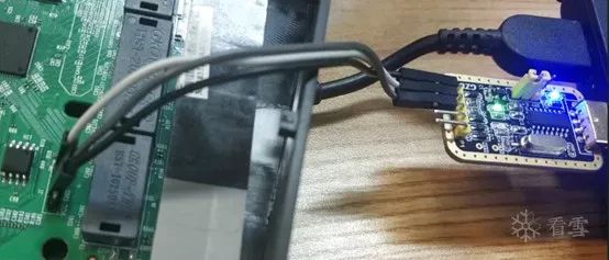
Step 2: Connecting the UART Pins to the Computer via TTL
USB to TTL wiring method:
-
GND pin connects to TTL’s GND
-
RXD pin connects to TTL’s TXD
-
TXD pin connects to TTL’s RXD
Step 3: Troubleshooting
After locating the pins, solder the pin headers, then connect to the computer using USB to TTL.
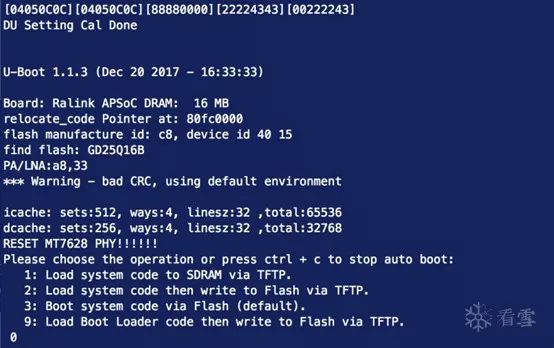
Open Serial, select the COM port, fill in the baud rate, start the router; normal startup information should appear, but if there is normal output of startup information but no input response, check the router hardware.
This router uses the MT7628AN chip; I found the chip’s DataSheet. I discovered that pins 147 and 148 correspond to TXD and RXD, respectively.
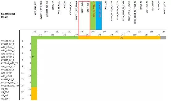
Observation
First, RXD, TXD, and other pins ultimately connect to the CPU. Physically, the serial port pins and chip pins are connected through a circuit. I suspect the manufacturer has interrupted the circuit from RXD to the chip during production.
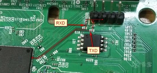
1. Verifying the Hypothesis
Having previously identified the chip pin for TXD, I took out the multimeter to check the circuit.
Set the multimeter to beep mode, place one probe on chip pin 147 and the other on the identified TXD pin. A continuous beeping sound indicates that the connection is intact, confirming that the previous steps were correct. However, testing chip pin 148 and RXD produced no sound, confirming my suspicion of tampering by the manufacturer.
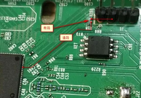
2. Identifying the Issue
I observed that there are three resistors near the debug pins: R89, R18, and R288. I set the multimeter to beep mode for testing.
R89 is associated with the TXD line, R18 is associated with the GND line, and R288 has two solder points but no resistor soldered. The line from chip pin 148 (RXD) to the first solder point is intact, and the UART pin (RXD) to the second solder point is also intact. The first resistor and the second solder point are disconnected; the issue is simple: there is a missing resistor here.
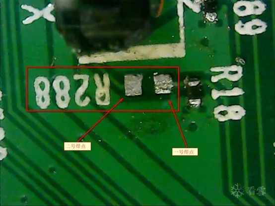
3. Resolving the Issue
The main function of the resistor is to divide the voltage. Since I don’t have a resistor on hand, I will use a simple and straightforward method: just solder a bit. I took out the soldering iron and solder wire to connect the two solder points of R288. Power on the router, connect the circuit, and normal input should occur.
Startup Information
Input

– End –

Author ID: maxk
https://bbs.pediy.com/user-449241.htm
This article is an original work by maxk.
Reprint must indicate the source from the KX community.
Popular Past Articles
1. C/C++ Deobfuscation Methods
2. APICloud Decrypting Local Resources to Reverse APP Algorithms to General Resource Decryption
3. My WeChat Data Monitoring Research and Development Process
4. Network Sandboxing! 2019 WCTF World Hacker Master Competition Kicks Off
5. How to Implement HTTPS Interception for Unconventional Packet Capture
﹀
﹀
﹀
Jinghua gathers talented individuals; ambitions align in pride and indulgence. This summer, let’s meet at KX, share drinks, and discuss the dreams of security technology.

Top 10 Topics Officially Announced! The Third KX Security Developer Summit is Coming!
↙Click the “Read the original text” below for more valuable content.