Overview of 8051 Microcontroller and 4-bit LCD Interface
This example explains how to connect a 16×2 LCD to the 8051 microcontroller in 4-bit mode, thereby reducing the number of microcontroller pins required. It covers software tools such as Keil uVision (for coding) and Proteus (for simulation). The code example demonstrates how to send commands to the LCD in two 4-bit nibbles using bitwise operations. Additionally, a video and source code are provided for further understanding of the project.
Components Used in the 8051 Microcontroller and 4-bit Mode LCD Interface:
- 8051 Development Board
- 16×2 LCD Display
- Keil uVision Software (C51 Compiler)
- Proteus Simulation Software
This example will demonstrate how to connect the LCD to the 8051 in 4-bit mode.
Step 1: Software Used:
1. Keil uVision: Keil has many products, so you need the C51 compiler.
2. Proteus Simulation Software: This is the software used for display simulation.
Step 2: Circuit Diagram:
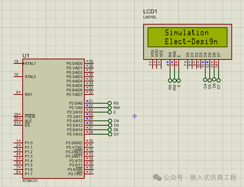
Step 3: How the Project Works:
Just like with an 8-bit LCD, we need to connect all 8 data pins of the LCD to the microcontroller. Therefore, we need to use 11 pins of the microcontroller since the LCD also has 3 control pins (rs, rw, e). The advantage of the 4-bit LCD is that we can save 4 pins of the microcontroller to use for other tasks.
Now I will extract a function from the code and explain how the command or LCD receives data. In our code, the first command instruction is
cmd(0x28);
Now it will return to its definition
void cmd(unsigned char a){
unsigned char x;
x=a&0xf0;
cmd1(x);
x=(a<<4)&0xf0;
cmd1(x);
}
So in the above function, you can see that a is 0x28. Now through x=a&0xf0, the low nibble will become 0. Because we used the AND operator with 0xf0. So only the high nibble has data, and then through cmd1(x) we send 0x20 to port 2, and since the LCD is connected to the high bits of port 2, it will receive 2. Now we need to immediately send the next nibble, which is 0x8. Therefore, you can see in the function x=(a<<4)&0xf0, we are shifting a 4 times, and then performing an AND operation with 0xf0.
So just understand that a<<4 is just 0x28<<4, which means 00101000<<4, so we will get 10000000, and when we AND it with 0xf0 we will get 0b10000000, which is 0x80, and from the next function cmd1(x) we send that data to the LCD, now it will receive 0x80, thus we have sent the entire data 0x28.
Therefore, the LCD will receive each command and data in the same way.
Step 4: Code and Video
#include <reg51.h>
sbit rs=P2^0;
sbit rw=P2^1;
sbit e=P2^2;
void delay(unsigned int);
void cmd1(unsigned char);
void dat1(unsigned char);
void cmd(unsigned char);
void dat(unsigned char);
void main(void)
{
unsigned char ch[]=”Simulation”;
unsigned char ch1[]=”Elect-Design”;
unsigned int i,j,k;
cmd(0x28);
cmd(0x01);
cmd(0x0c);
cmd(0x83);
cmd(0x00);
for(i=0;ch[i]!=’\0′;i++)
dat(ch[i]);
cmd(0xc3);
for(j=0;ch1[j]!=’\0′;j++)
{
dat(ch1[j]);
}
while(1){
for(k=0;k<16;k++)
{
cmd(0x1c);
}
}
}
void delay(unsigned int t)
{
unsigned int i,j;
e=1;
for(i=0;i<t;i++)
for(j=0;j<1275;j++);
e=0;
}
void cmd(unsigned char a)
{
unsigned char x;
x=a&0xf0;
cmd1(x);
x=(a<<4)&0xf0;
cmd1(x);
}
void dat(unsigned char a)
{
unsigned char x;
x=a&0xf0;
dat1(x);
x=(a<<4)&0xf0;
dat1(x);
}
void cmd1(unsigned char ch)
{
P2=ch;
rs=0;
rw=0;
delay(10);
}
void dat1(unsigned char ch)
{
P2=ch;
rs=1;
rw=0;
delay(10);
}
Follow us (operation reference article: Send a message to the public account), click the blue text at the top “Embedded Simulation Engineering” or long press to identify the QR code to follow
Reply in the public account
5131
After receiving, the free Keil project link for this project will be automatically sent.