ver0.1
Introduction
In the previous article, we introduced the software architecture of the PSCI mechanism (including virtualization architecture). This architecture may seem simple, but it is not difficult at all, especially if you have a certain foundation. If you find it challenging, you should solidify your basics. In other words, if your boss asks you to work on the stability and optimization of the Power section, you may not be able to handle it yet. The PSCI architecture can be divided into two parts: the proxy and the implementation. Depending on the exception model, the PSCI proxy mainly operates at EL1 and EL2, while the PSCI implementation is at EL3. The main task of the PSCI proxy is to determine the state of a physical core based on the status of each VM and notify EL3, allowing the firmware’s PSCI implementation to decide the state of the (PE-(PE-Core\Cluster\System)) and communicate with the SCP, which in turn communicates with the PPU distributed throughout the system architecture, thereby affecting the power modes of these power domains and completing the transition between software-level power states and hardware-level power modes. One key point here is how the power state of a physical core is transformed into a set of (PE-Core\Cluster\System) states for the SCP. This is where the coordination role of PSCI comes into play, and today we will discuss this in detail. Before reading this article, I hope everyone will read our previous articles to grasp some basics and get a feel for the topic:
(1)[V-02] Virtualization Basics – CPU Architecture (Based on AArch64)
(2)[A-03] ARMv8/ARMv9 – Multi-level Cache Architecture
(3)[A-21] ARMv8/v9 – SMMU System Architecture and Function Overview
(4)[A-25] ARMv8/v9 – GIC System Architecture (Hardware Foundation of Interrupts)
(5)[A-38] ARMv8/v9 – Generic Timer System Architecture
(6)[A-41] ARMv9/v8 – Power Management System Architecture
(7)[A-42] ARMv9/v8 – Overview of Power Management Principles (SCP Service Overview)
(8)[A-43] ARMv9/v8 – Introduction to Power Control Framework (PCF)
(9)[A-0x2c] ARMv9/v8 – Power Management Domains (Voltage Domain/Power Domain)
(10)[A-45] ARMv9/v8 – Power Modes
(11)[A-46] ARMv9/v8 – Power States
(12)[V-05] Virtualization Basics – Exception Model (AArch64)
(13)[A-47] ARMv9/v8 – Power State Management Software Architecture (PSCI Architecture)
Body
1.1 Background of the Coordination Mechanism
Through the introduction of the PSCI architecture, we need to understand that PSCI is designed to decouple the power state management of ARM’s PE-Cores for the upper-level operating systems (EL0/EL1) from the control of the actual physical device’s power modes. Let’s briefly review the mapping relationship between the power states and power modes of PE-Cores (as shown in Figure 1-1).
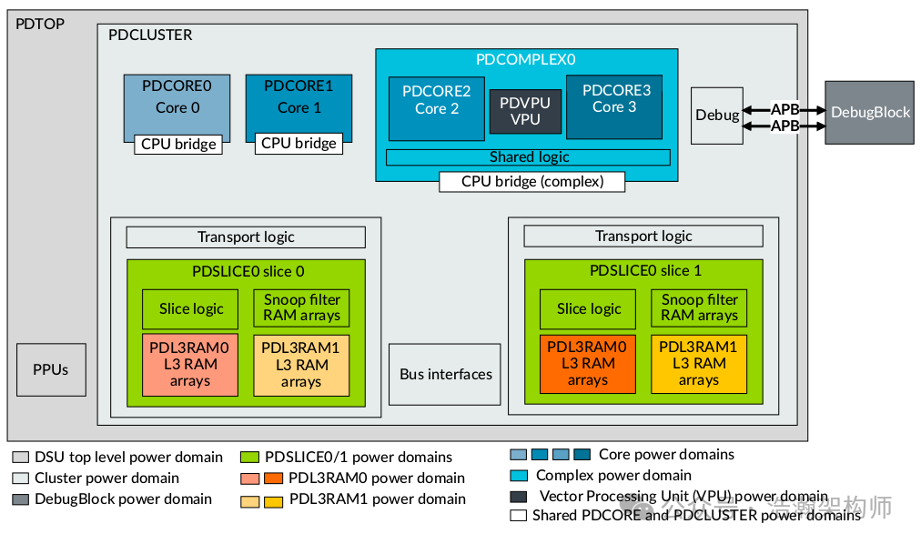
Figure 1-1 DSU-120 power domains
The microarchitecture of modern CPUs has become very complex, with one notable feature being the integration of many functional units to assist the CPU. From the perspective of power management, these functional units are seen as individual power domains. These power domains operate under different power modes depending on various scenarios, as shown in Figure 1-2.
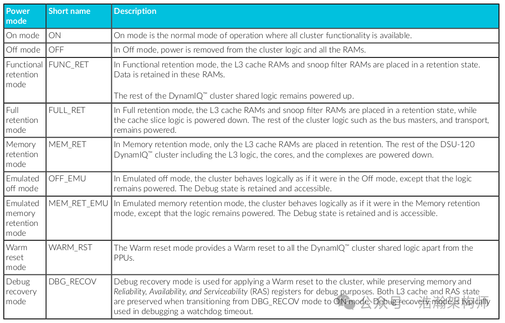
Figure 1-2 DSU-120 power domains
We zoom in on Figure 1-1 DSU because we know that the core power domain of interest to PSCI is the power state of the CPU Cluster (DSU) PE-Cores. Let’s take a look at the power modes supported by PE-Cores, as shown in Figures 1-3 and 1-4.
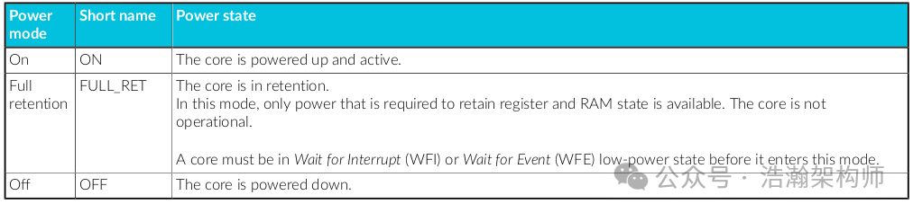
Figure 1-3 Cortex-A720 core power modes (Part-1)
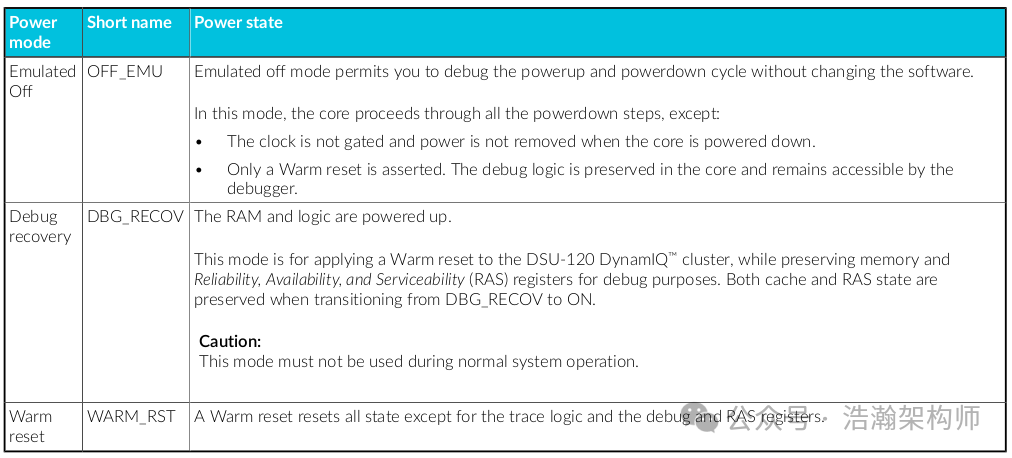
Figure 1-4 Cortex-A720 core power modes (Part-2)
Specifically, a PE-Core has six power modes, as introduced in the above figures. These power modes can transition between operational modes under different working conditions, as shown in Figure 1-5.
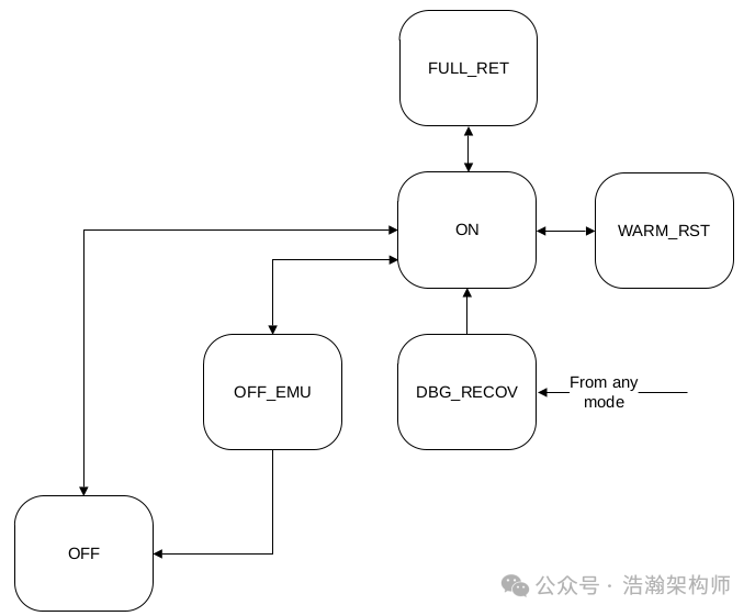
Figure 1-5 Cortex-A720 core power mode transitions
The transition of power modes for PE-Cores, as the most important power domain in the DSU, will also affect the internal working conditions provided to the CPU Cluster for the PE-Cores. For example, if all PE-Cores within the DSU are turned OFF, then the DSU certainly does not need to maintain its previous power mode, meaning that the DSU power mode will also change with the power mode of the PE-Cores, as shown in Figure 1-6.
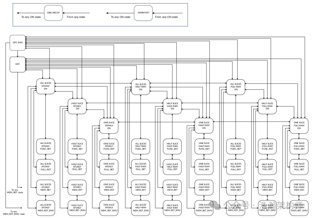
Figure 1-6 DSU-120 DynamIQ cluster PPU mode transitions
Although not very rigorous, in most cases, the starting point for these power mode changes is the PE-Cores, as all components on the DSU serve the PE-Cores. The trigger for switching the power mode of the PE-Cores actually comes from the intervention of OSPM, which promotes the change in power modes through intervention in power states, leading to a series of subsequent reactions. This part has been detailed in our previous discussion of the PCSA system architecture and working principles. Here, we only attach a diagram to help everyone find the boundary between the software and hardware of the ARM power management system, as shown in Figure 1-7.
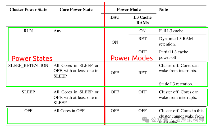
Figure 1-7 Mapping relationship between power states and power modes
From a hardware perspective, the SCP helps us absorb the strategies for power mode transitions, while the PPU helps us implement the switching of power modes. From a software perspective, OSPM needs to absorb the work of transitioning power states. However, as shown in Figure 1-1, a DSU has so many PE-Cores, taking DSU-120 as an example:
You can configure the cluster to have between one and 14 cores. Each core within a complex counts towards the total number of cores in the cluster. This is in addition to any cores in the cluster that are not in complexes (stand-alone cores).
This latest generation of the Cluster can have up to 14 PE-Cores. Just because one PE-Core is idle does not mean that the others are idle. Moreover, with the entire software world being virtualized, the working conditions in the software world have become even more complex. Therefore, it is necessary to decouple the management of power states from OSPM. OSPM only needs to select the appropriate power state based on its own working conditions and directly call the PSCI interface. This part of the work is referred to as the PSCI-Proxy, which is responsible for collecting the desired power states from various software modules in the software world under the current working conditions. If everyone has a consistent demand for power states, that’s fine. However, if there are inconsistencies, for example, if PE-Core-1 wants to be ON while PE-Core-2 wants to be OFF, then there is a conflict in the software world regarding the current power state. This is where the PSCI mechanism comes into play, arbitrating according to the established power state management strategy to obtain an arbitration result, which is then output to the SCP to complete the subsequent power mode management process. This arbitration process is essentially the coordination process of the PSCI mechanism, and the specific implementation can be referred to as the PSCI-Server side.
1.2 PSCI Coordination Mechanism
Through the background description, we divide the work of PSCI into two parts: Proxy and Server. The Proxy is responsible for collecting states, while the actual coordination of power states is completed on the PSCI-Server side. Next, we will study this part in detail.
1.2.1 Power States (shallow or deep)
The PSCI-Server side, as the coordinator, must find a balance between power consumption and system wake-up latency, and the metric for this is the depth of the Power State:
When a core is idle, the OSPM transitions it into a low-power state. Typically, a choice of states is available, with different entry and exit latencies, and different levels of power consumption associated with each state. The state that is used typically depends on how quickly the core will be needed again. The power states that can be used at any one time might also depend on the activity of other components in a SoC, in addition to the cores. Each state is defined by the set of components that are clock-gated or power-gated when the state is entered. States are sometimes described as being shallow or deep. Typically, a state X is said to be deeper than a state Y if:
• The set of components that are powered down in state X subsumes and is a superset of the corresponding set for state Y.
• The set of components that is powered down in state X is the same as the corresponding set for state Y, but various power modes are supported, and the modes used in state X save more power than those used in state Y.
The time required to move from a low-power state to a running state is known as the wakeup latency. Generally, deeper power states have longer wakeup latencies, but this is not necessarily always the case.
The manual describes that the deeper the power state, the greater the wakeup latency. So how do we determine which power state is deeper? “Deeper”:
(1) Taking the Cluster as an example, once an SoC design is finalized, the various components on the DSU will be divided into different power domains. When a power state needs to shut down more power domains, that state is considered deeper. As described in the manual:
In addition to retention features, the DynamIQ ™ Shared Unit-120 (DSU-120) can further reduce static leakage power, using three power-down features.
• Optionally power down half, or all except one, of the L3 cache slices.
• Within each L3 cache slice, power down a portion of the L3 cache RAM that the cache slice contains.
• Use Quick Nap with L3 data RAMs, for fine-grained automatic transitions to a low-leakage power mode.
Similarly, in retention mode, depending on the requirements, further subdivision and slicing of the L3 Cache can be performed. If a power state X needs to manage the L3 Cache state, while another power state Y does not need to manage the L3 Cache power state, then X is deeper than Y.
(2) If both power states manage the same number of power domains, then we look at which one saves more power. Still taking the L3 Cache as an example, if both power states need to pay attention to the power modes of the L3 Cache, and state X needs to turn off the L3 Cache while state Y does not, then X is deeper than Y because X will definitely save more power than Y. Of course, the wake-up time for state X will also be longer than for state Y because it needs to power on an additional power domain, the L3 Cache.
Using the rules in (1) and (2), we can refer to Figure 1-8 to see the depth relationship of the power states of the PE-Cores.
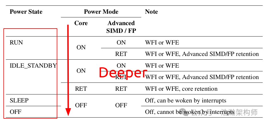
Figure 1-8 Cortex-A55: mapping AP core power states to modes
1.2.2 Power State System Topologies
Typically, the power management of an SoC involves power domains as shown in Figure 1-9:
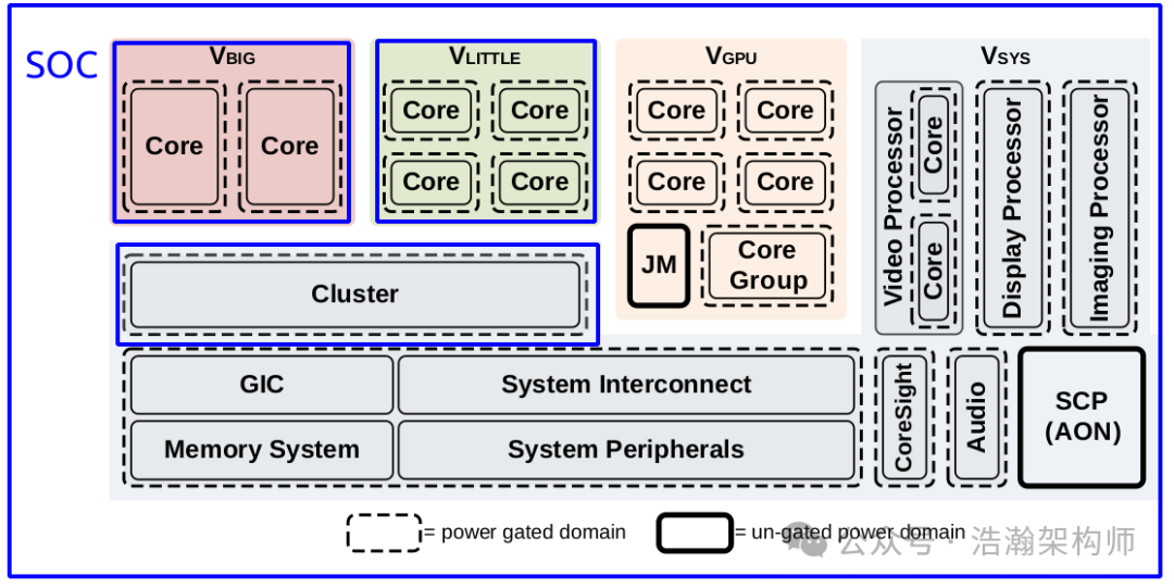
Figure 1-9 SoC voltage and power domain partitioning example
All power domains (each Power Domain) are interconnected, and they must consider the emotions of other domains within the organization (SoC), especially the relationships between power domains that have dependencies must be harmonious and not cause issues. Even when the PSCI mechanism covers the power states of PE-Cores during migration, it must also consider the global perspective. Therefore, the second factor that the PSCI-Server side must consider is the inheritance relationship of the power states of each power domain:
Although idle power management is driven by thread behavior on a core, the OSPM can place the platform into states that affect many other components beyond the core itself. For example, if the last core in a SoC goes idle, the OSPM can target power states that affect the whole SoC. The choice is also driven by the use of other components in the system, and therefore might require coordination among multiple agents. A typical example is placing the system into a state where memory is in self-refresh when all cores, and any other requesters, are idle. The OSPM has to provide the necessary power management software infrastructure to determine the correct choice of state.
Each component in a power domain has a set of power states that affect the components in the domain. Although physically the power domains are not necessarily built in a hierarchical fashion, from a software control point of view, they are arranged in a logical hierarchy. The hierarchy arises out of ordering dependencies that are required when placing the power domains into different power states. For example, consider a power domain that encompasses a shared cache, and power domains for the cores that use it. In such a system, the core power domains must be powered down before the shared cache domain, to guarantee correct operation.
We simplify Figure 1-9 to retain only the parts strongly related to PSCI, as shown in Figure 1-10:
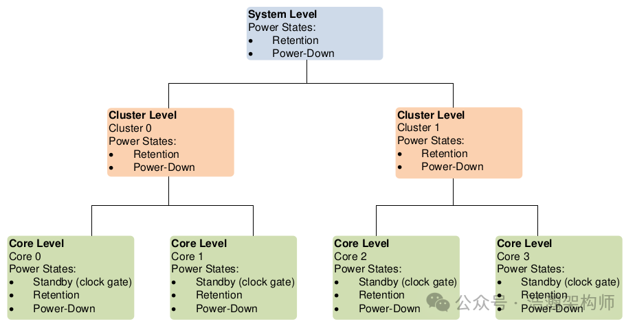
Figure 1-10 Example power domain topology
Combining Figures 1-1, 1-9, and 1-10, we can understand the descriptions in the manual more deeply:
(1) After high-level abstraction, the power states of PE-Cores, as the terminal nodes at the power domain level, will affect at least two layers of power domains (Cluster and System) besides themselves.
(2) These two layers of power domains are also associated with many other power domains. For example, the important L3 Cache within the Cluster, thus the retention state of the Cluster is deeper than that of the PE-Core. Similarly, the retention of the System is deeper than that of the Cluster because the System is associated with more components in the power domains.
(3) The PSCI mechanism’s intervention in the power states of PE-Cores will indirectly affect the power states of the Cluster and System. For example, as given in the manual, if all PE-Cores on a Cluster enter retention mode, the Cluster no longer needs to maintain its run state. After handling the cache bus, it can also consider designing a strategy for the Cluster to enter sleep mode. An important task for the PSCI-Server is to maintain a global perspective and not just focus on its own area.
(4) It is also important to note that PSCI supports operations at the system level for power states, meaning that the power state of the root node will also inversely affect the power states of child nodes. Below, we quote the manual’s description in full, which provides a broader perspective (Multiple SoCs, multiple software architectures). It is difficult to decide which part to excerpt (we will plan a dedicated article to introduce this part later, initially considering the software implementation based on a specific chip from MTK or Qualcomm).
PSCI provides an interface to allow an OS to request system shutdown, system reset, and system suspend (suspend to RAM and suspend to disk). This allows a silicon vendor to provide a common implementation of these functions that is independent of the supervisory software running on the device.
The usage of the term system in the PSCI function definitions refers to the machine view that is available to the calling OS. If the caller is a guest running in a virtual machine system, shutdown, reset, and suspend operations affect the virtual machine and might not result in any physical power changes. However, if a hypervisor is not present, or the caller is a hypervisor, the result is physical changes in power. Even if the caller is running on a physical machine, the term system might not mean the entire physical machine. For example, consider an advanced server system consisting of multiple boards, each with a board management controller (BMC), and each containing multiple SoCs. Such a system could run an OS instance per SoC. In this example, a PSCI command to shut down the system applies to a single SoC, while powering down the entire board requires access to the BMC through an administration interface that is beyond the reach of the calling OS or a PSCI implementation. In this document, the term system refers only to the machine view that is visible to an OS. In the example above (Pic 1-10), this maps to a single SoC.
1.2.3 Power State Coordination
Having clarified the two dimensions of the PSCI mechanism’s coordination of power states (depth and topology), we will now enter the core aspects of the PSCI mechanism:
Entry into local power states for high-level nodes in a power topology (for example, clusters or systems) requires coordinating child nodes. For example, entry into a cluster power-down state is only possible when all cores in the cluster are powered down. To achieve this, every core but the last one must be placed into a power-down state, and the last one places itself and the cluster into a power-down state.
PSCI supports two modes of power state coordination: platform-coordinated mode and OS-initiated mode.
The PSCI-Server must coordinate the states of each PE-Core at the system architecture level before determining the power states of the upper-level nodes (Cluster/System). ARM provides two implementation modes for the PSCI-Server: platform-coordinated mode and OS-initiated mode.
1.2.3.1 Platform-coordinated Mode
Prior to PSCI 1.0, only the platform-coordinated mode was supported:
This is the default mode of coordination. In this mode, the PSCI implementation is responsible for coordinating power states. When a core has no more work to do, the OSPM requests the deepest state it can tolerate for that core and its parent nodes. For power state requests that affect a topology node above the core level, the implementation chooses the deepest power state that can be tolerated by all the cores in the node. In effect, the power state request expresses the following two constraints:
• The caller allows entry to states up to this depth, but no deeper.
• The caller cannot tolerate a higher wakeup latency than that associated with the requested state.
The PSCI implementation then determines the deepest state that satisfies the constraints expressed by each core in a given node.
The principles of coordination in this mode must comply with two constraints:
(1) The requested power state of the applying node cannot be set to a deeper depth after arbitration by the PSCI-Server. If the power state depth State A < State B < State C, and if the PE-Core requests State B, then under no circumstances can the PE-Core be set to State C.
(2) The applying node must adhere to the principle of minimum wakeup latency. If the power state depth State A < State B < State C, but the wakeup latency State (Wakeup Delay) A < State (Wakeup Delay) C < State (Wakeup Delay) B (which generally should not happen). If a PE-Core requests State C, then according to rule (1), it can be set to State B or State A after passing through PSCI’s rules, but with the addition of rule (2), this PE-Core cannot be set to State B because the wakeup latency of State B is longer than that of State C. The possible choices are State A or maintaining State C. Of course, in practice, the implementations of various vendors regarding power states rarely encounter such situations.
Based on the above rules, let’s see how the platform-coordinated mode works, as shown in Figure 1-11:
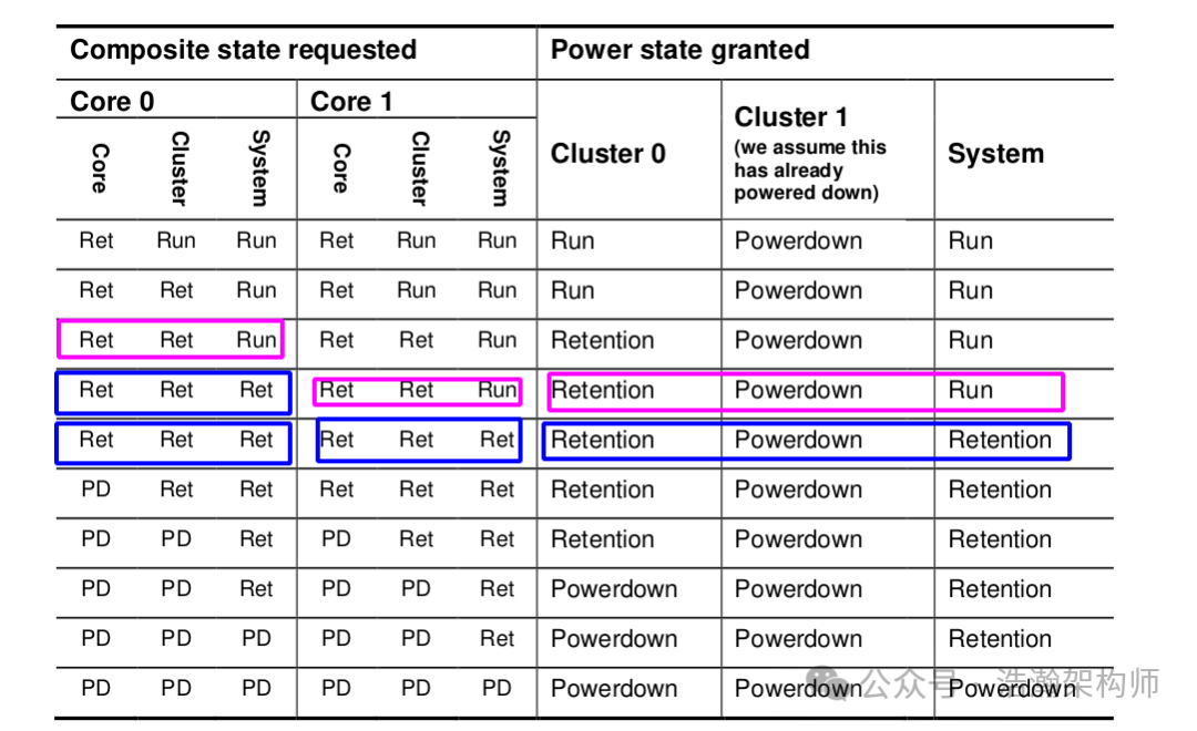
Figure 1-11 Example platform coordination of power state requests
The PSCI-Proxy (the interface through which power state requests from OSPM are sent) is recommended by ARM to be in a coded form, as shown in Figure 1-12:
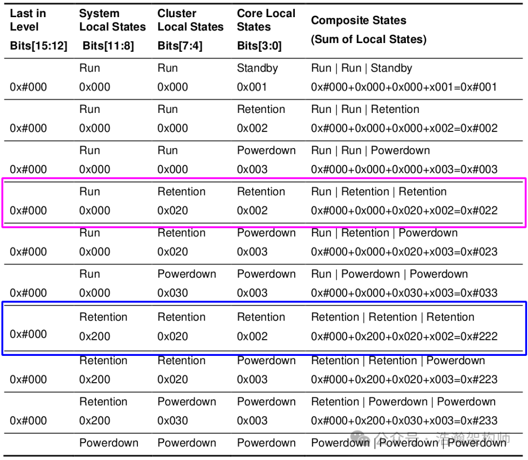
Figure 1-12 StateID encodings for local and composite states in example system
By combining Figures 1-11 and 1-12, it becomes clearer through the same color for comparison confirmation.
(1) The PSCI-Proxy collects the current state of the PE-Core and summarizes it to the PSCI-Server. Each request includes the three-level states of the power topology where the current PE-Core is located (Core, Cluster, System).
(2) After the PSCI-Server receives the states of PE-Core 0 and PE-Core 1, it then decides the final three-level state. For example, only after all PE-Cores in the topology branch (Core, Cluster, System) request to enter retention state can the System enter retention state.
(3) Other state transitions can be deduced by the above rules, noting that this part should refer to the basic implementations of various chip OEMs, and the specifics of mass production projects should be based on the chip manual.
1.2.3.2 OS-initiated Mode
PSCI introduced the OS-initiated mode after version 1.0:
Introduced in PSCI 1.0, OS-initiated mode places the responsibility for coordination on the calling OS. In the OS-initiated coordination scheme, OSPM only requests an idle state for a particular topology node when the last underlying core goes idle.
When a core goes idle, it always selects an idle state for itself, but idle states for higher-level nodes such as clusters are only selected when the last running core in the node goes idle. In addition, the implementation only considers the most recent request for a particular node when deciding on its idle state.
This mode requires clear indication of the last state of the current PE-Core (the first column of Figure 1-12, Last in Level) cannot all be 0, and must be explicitly marked, as shown in Figure 1-13:
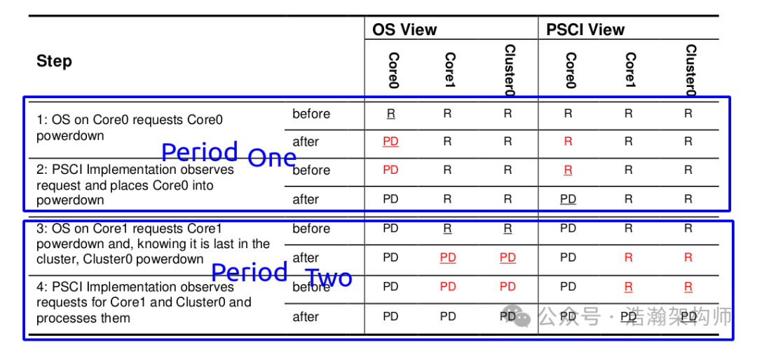
Figure 1-13 StateID sample encoding
Let’s understand the OS-initiated mode coordination through an example, as shown in Figure 1-14:
Figure 1-14 Example flow: Cluster power-down entry
Let’s look at the manual’s description of this mode:
As the table illustrates, there are periods (marked in red) where the OS view of core state and the implementation view of core state do not match. This might happen after the OS requests a state, but before the implementation has processed the request. This can also happen when a core powers up, as the implementation sees the core before the OS. To implement OS-initiated mode, it is necessary to deal with the races that arise due to the differing views of core state. Solving the races gives rise to the following requirements:
• The implementation must deny any requests from the calling OS that are inconsistent with its view of core state.
• The calling OS must indicate when the calling core is the last running core at a particular power hierarchy level. It must also specify which power hierarchy level the core is last in, for example, whether it is the last core in the cluster or the last core in the system.
In the OS-initiated mode, the transition of power states initiated from a PE-Core takes one cycle to complete, so the OS-level view of power states and the PSCI-Server’s view will align at the end of one cycle. This means it cannot respond immediately like in platform-coordinated mode. The main reason is that OS-initiated mode is generally applied in more complex system architectures (virtualization architecture + security architecture + multi-SoC environment), and this arbitration strategy requires a cycle to comprehensively consider the needs of all parties to provide SCP with a clear power state setting. In contrast, the response strategy of platform-coordinated mode is simpler and more straightforward, making it less nuanced and flexible. This convenience comes at a cost:
(1) The current PE-Core must indicate the Last In Level information required before initiating operations, which requires the PSCI-Proxy to maintain the operational states of these PE-Cores at the Cluster and SoC levels.
(2) The PSCI-Server, as the implementation side of PSCI, needs to handle concurrent access to various PE-Cores within one cycle, especially to avoid illegal state requests, including but not limited to the following situations (also depending on the specific implementations of various chip OEMs, particularly the division of power handling strategies between SCP and AP):
• The migration of power states does not conform to the state machine transitions mapped to power modes (Figures 1-5, 1-6).
• Inconsistent behavior in power state requests for the same PE-Core within one processing cycle, such as just requesting the PE-Core’s state to be RUN, but then requesting the Cluster of the PE-Core to be PD or retention state.
• Conflicts in state requests between PE-Cores within one processing cycle, which must be coordinated according to the rules of depth and wake-up time.
1.2.3.3 Differences in Implementations of the Two Coordination Modes
This part has been discussed in our previous discussion of the PSCI architecture, so we will not elaborate further, but will only mention the differences between them. First, let’s look at the typical architecture of platform-coordinated mode, as shown in Figure 1-15:
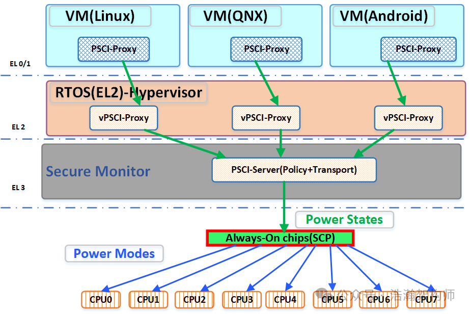
Figure 1-15 Platform-coordinated mode SW ARCH
Don’t worry, let’s look at the typical architecture of OS-initiated mode, as shown in Figure 1-16:
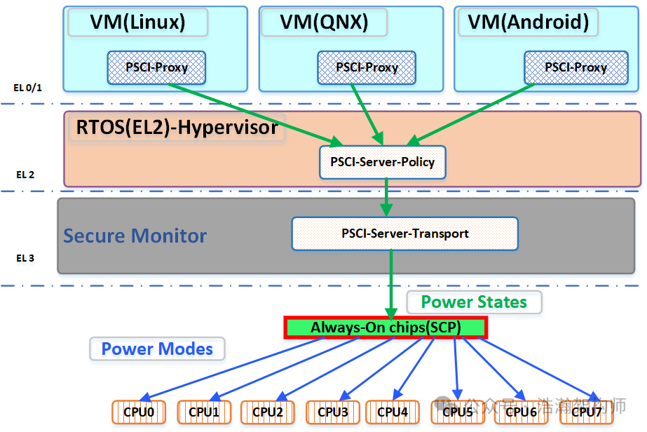
Figure 1-16 OS-initiated mode SW ARCH
The differences between the two modes have been discussed in previous sections, and here are some additional software-level considerations:
(1) First, the decision-making entity:
• Platform-coordinated mode is completed in the firmware program at EL3, and the vendors of various VMs and virtualization providers have almost no discretion.
• OS-initiated mode is completed in the hypervisor above EL3 or directly in EL1 (depending on the specific virtualization implementation), which gives software vendors more customization space (unless you are very confident, it is recommended to use the default strategy of the chip vendor).
(2) Efficiency:
• Platform-coordinated mode requires various VMs to frequently trap into EL3 and go through EL2, which incurs a significant overhead if the power state of the PE-Core switches frequently.
• OS-initiated mode can skip some of the operations that trap into EL3, optimizing the process.
(3) Trends:
• Platform-coordinated mode is more suitable for simpler system architectures with less complex power states, such as MCUs and early ARM-based SoCs, with the greatest advantage being fast decision-making.
• OS-initiated mode is more suitable for complex system architectures (phones, servers) with complex power states, with the greatest advantage being the ability to handle more scenarios, although decision-making is relatively slower than platform-coordinated mode, as it considers the states of more PE-Cores in the system architecture.
Conclusion
This concludes our discussion on the PSCI coordination mechanism. We started by discussing the mapping from power states to power modes and detailed the necessity of PSCI’s intervention in coordinating the power states of PE-Cores. Before introducing the specific coordination mechanisms of PSCI, we discussed two important foundational concepts: the depth of power states and the topology of power states. With this preparatory knowledge, we began to introduce the two current coordination modes of PSCI: platform-coordinated mode and OS-initiated mode. We conducted a detailed analysis of these two modes, including the rules of integration, encoding specifications, and some business content. Finally, we introduced the main differences between the two modes at the software architecture level. Originally, we intended to introduce the specific implementation and workflow of the PSCI interface in this article, but due to space limitations, we will have to publish it in two articles. That’s all for today, thank you all for your attention, shares, and comments.
Reference
[01] <DEN0050D_Power_Control_System_Architecture.pdf>
[02] <armv8_a_power_management_100960_0100_en.pdf>
[03] <Power_Policy_Unit_Architecture_Specification_V_ARM_DEN_0051E.pdf>
[04] <DEN0024A_v8_architecture_PG.pdf>
[05] <79-LX-LD-s003-Linux设备驱动开发详解4_0内核-3rd.pdf>
[06] <80-PGxxx-35_QNX_Thermal_Manager_Overview.pdf>
[07] <80-pgxxx-7_n_qnx_power_management_software_architecture_ref.pdf>
[08] <80-ARM-POWER-HK0001_一文搞懂ARM_SoC功耗控制架构.pdf>
[09] <Arm_Power_and_Performance_Management_SCMI_White_Paper.pdf>
[10] <80-ARM-POWER-cs0001_Arm-SoC-power功耗控制架构.pdf>
[11] <80-LX-LK-cl0009_深入理解Linux电源管理.pdf>
[12] <DEN0056D_System_Control_and_Management_Interface.pdf>
[13] <arm_total_compute_2021_reference_design_software_developer_guide_en.pdf>
[14] <arm_total_compute_2022_reference_design_software_developer_guide_en.pdf>
[15] <arm_cortex_m85_processor_trm_en.pdf>
[16] <DEN0108_00eac0_smcf-archl-Specification.pdf>
[17] <DEN0022F.b_Power_State_Coordination_Interface.pdf>
[18] <MTxxxx_SCP_User_Manual_V1.0.pdf>
[19] <learn_the_architecture_arm_system_architectures_en.pdf>
[20] <arm_dsu_110_trm_101381_0400_11_en.pdf>
[21] <DEN0077A_Firmware_Framework_Arm_A_profile_EAC0.pdf>
[22] <80-LX-POWER-PSCI-cs0001_Linux-PSCI框架.pdf>
[23] <learn_the_architecture_realm_management_extension_guide.pdf>
Glossary
AP – application processor
OSPM – Operating System Power Management
WFI – Wait For Interrupt
WFE – Wait For Event
DVFS – Dynamic Voltage and Frequency Scaling
SCU – Snoop Control Unit
OPP – Operating Performance Point
PSCI – Power State Coordination Interface
PPU – Power Policy Unit
PCSA – Power Control System Architecture
SoC – System-on-Chip
PCF – Power Control Framework
SCP – System Control Processor
BSP – board support package
SCMI – System Control and Management Interface
EAS – Energy Aware Scheduling
IPA – Intelligent Power Allocation
ACPI – Advanced Configuration and Power Interface
LPI – Low-Power Idle
CPPC – Collaborative Processor Performance Control
PCSM – power control state machine
AOSS – Always-on subsystem
PMIC – Power Management Integrated Circuit
JM – job manager
AON – always on domain
SBSA – Server Base System Architecture
CLK_CTRL – Clock Controller
LPD – Low Power Distributor
LPC – Low Power Combiner
P2Q – P-Channel to Q-Channel Convertor
GPIO – General Purpose IO
RAS – Reliability, Availability, and Serviceability
STR – Suspend to RAM
PPF – Privileged platform firmware