01Basic Understanding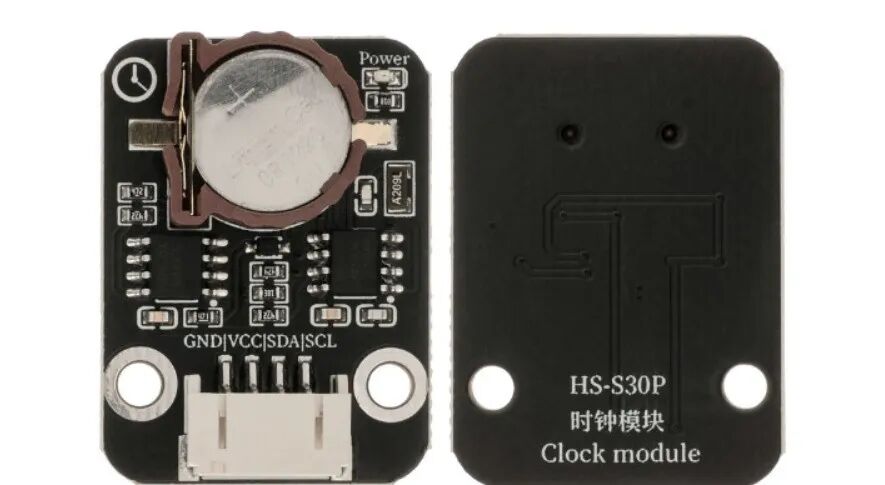 Model:HS-S30PName:Clock ModuleSeries:Communication ModuleDescription:This is a module that integrates a real-time clock (RTC) function, with a built-in high-precision crystal oscillator and backup battery interface, capable of continuously providing year, month, day, hour, minute, and second information. It supports time calibration and power-off endurance, and can interact with microcontrollers such as Arduino through communication protocols, making it a core component for time synchronization and timing control..Usage Scenarios:Implementing timed interactions in smart homes (e.g., automatically turning on lights at 7 AM, turning off power to outlets at 11 PM); setting game duration limits in children’s toys (e.g., automatically pausing toys after 15 minutes); recording equipment start and stop times in industrial production (e.g., statistics on production line operation duration); in education, aligning with the “Artificial Intelligence General Education Guidelines for Primary and Secondary Schools (2025 Edition)” by building a “timed reminder system” and “multi-device time synchronization device” to help students understand the principles of real-time clocks and data interaction logic; providing timed medication reminders for the elderly in assistive technology (e.g., triggering a buzzer at a fixed time every day); recording time nodes in laboratory experiments (e.g., timing chemical reactions).Interdisciplinary Integration:Physics, Mathematics, Labor, Information TechnologyEthical Education:The device usage time data recorded by the clock module (e.g., appliance usage periods) may leak user living patterns, requiring clear boundaries for data collection; the recycling and disposal of batteries and chips in electronic waste necessitates discussion on environmental responsibility; critical scenarios relying on timing systems (e.g., medical reminders) require consideration of emergency plans for technical failures; different devices having unsynchronized times may lead to chaotic interactions, prompting a discussion on the necessity of a “unified time standard”; over-reliance on timing functions may reduce individuals’ time management abilities, necessitating a balance between technological convenience and personal planning.
02Technical Parameters
Operating Principle:
The module has a built-in real-time clock (RTC) chip that generates a stable time reference signal through a 32.768kHz crystal oscillator, achieving precise counting of year, month, day, hour, minute, and second. It supports backup battery power, maintaining time operation even during power outages; it connects to microcontrollers via the I2C communication protocol, allowing time to be read or set while filtering high-frequency interference signals to ensure stable data transmission.
Parameter Analysis:
G(GND): Power input negative/ground
V(VCC):Power input positive/voltage
S(Signal):SignalOutput interface
Clock accuracy: ±2ppm (at room temperature, annual error ≤ 1 minute)Operating temperature: -40℃~85℃Backup battery: CR2032 (lifespan ≥ 5 years, automatic switch after power outage)Communication protocol: I2C (supports speeds of 100kHz/400kHz)Time format: supports 24-hour/12-hour format, including automatic leap year correction03Code Example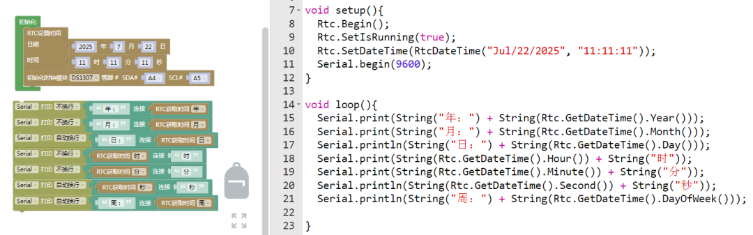
The connection pins are default.
Note: Students should observe the data, then disconnect the power, and test again after powering on.
04Safety Measures
1.Power must be turned off before wiring, and confirm the positive and negative terminals of VCC and GND; reversing connections may burn the RTC chip;
2. When installing the backup battery, pay attention to the positive and negative terminals to avoid leakage and corrosion of the circuit board;
3. Avoid using in strong electromagnetic environments (e.g., near motors, transformers) to prevent interference with the crystal oscillator signal;
4. Do not short-circuit the interface pins with metal objects, as this may cause permanent damage to the module;
5. In high-temperature and high-humidity environments (e.g., bathrooms), a protective case should be added to prevent moisture from corroding the chip;
6. During debugging, ensure that the I2C address does not conflict with other devices (default address 0x68);
7. If not used for a long time, remove the backup battery to prevent leakage from damaging the module.
05Extensions
Students can try the following methods:
1. Combine the clock module with the HS-S26A temperature and humidity sensor to record environmental temperature and humidity changes at different times, drawing a “time – temperature and humidity” curve;2. Link with the HS-F07P active buzzer to create a timed alarm clock (e.g., setting reminders for class times);3. Build a “timed watering system” that controls a water pump to work at scheduled times, understanding the application of time-triggered logic in the Internet of Things. Arduino Sensors: HS-S01A Infrared SensorArduino Sensors: HS-S02P Infrared Sensor (Obstacle Avoidance)Arduino Sensors: HS-S03P Ultraviolet SensorArduino Sensors: HS-S05P Sound SensorArduino Sensors: HS-F07P Active BuzzerArduino Sensors: HS-S08P Flame SensorArduino Sensors: HS-S09LB Raindrop SensorArduino Sensors: HS-S09PC Soil Moisture Sensor
Arduino Sensors: HS-S10P Mist Sensor
Arduino Sensors: HS-S11-L Gas Sensor
Arduino Sensors: HS-S20P Ambient Light Sensor
Arduino Sensors: HS-S21P Tilt SensorArduino Sensors: HS-S22P Grayscale SensorArduino Sensors: HS-S23P Infrared Receiver ModuleArduino Sensors: HS-S24P Digital Temperature SensorArduino Sensors: HS-S26A Temperature and Humidity SensorArduino Sensors: HS-S28P Potentiometer
Arduino Sensors: HS-S29P Infrared Transmitter Module
 — Previous Recommendations —