“ The ESP32-S3 features dual-core processors, CPU0 and CPU1, along with an ultra-low-power co-processor (ULP). CPU0 is responsible for system initialization and complex computations, while CPU1 handles real-time tasks in parallel. The ULP operates at low power when the main cores are in sleep mode. The three cores collaborate through code to allocate tasks efficiently, balancing high-performance processing with low power consumption, suitable for various scenarios such as Wi-Fi connectivity and audio processing.”
01
—
Definition and Function
CPU0:
CPU0 is one of the main control cores of the ESP32-S3, based on the Xtensa LX7 architecture. It is responsible for system initialization, core task scheduling, peripheral management, and complex computations, serving as the computational and control hub of the chip, coordinating the operation of various components and handling high-priority tasks.
CPU1:
CPU1, like CPU0, is a processor core based on the Xtensa LX7 architecture, functioning as a collaborative unit with CPU0. It can run programs independently or share computational loads, primarily used for parallel processing tasks, real-time data processing, and control of specific peripherals, enhancing the system’s multitasking capabilities and response speed through dual-core collaboration.
Ultra-Low-Power Co-Processor (ULP):
The ultra-low-power co-processor is an auxiliary processing unit designed specifically for low-power scenarios in the ESP32-S3. It employs a simplified architecture (such as ULP-FSM or ULP-RISC-V) and can operate independently while the main core is in sleep mode, focusing on simple task processing in low-power states, such as sensor data collection, periodic monitoring, and wake-up condition evaluation, minimizing system standby power consumption.
02
—
Comparison Table of Key Features, Functions, and Application Scenarios
|
Item |
CPU0 |
CPU1 |
Ultra-Low-Power Co-Processor (ULP) |
|
Core Architecture |
Xtensa LX7 32-bit Processor |
Xtensa LX7 32-bit Processor |
ULP-FSM (Finite State Machine) or ULP-RISC-V (RISC-V Architecture) |
|
Maximum Frequency |
240MHz |
240MHz |
8MHz (Internal RC Oscillator) or 16MHz (External 32MHz Crystal Divider) |
|
Power Consumption Level |
High (mA level) |
High (mA level) |
Very Low (μA level) |
|
Memory Access Range |
Full System RAM and Peripherals |
Full System RAM and Peripherals |
ULP-FSM: 8KB RTC Slow Memory (RTC_SLOW_MEM) ULP-RISC-V: 8KB RTC Slow Memory (RTC_SLOW_MEM) and 64KB RTC Fast Memory (RTC_FAST_MEM) |
|
Operating State Support |
Normal Operation, Various Sleep Modes |
Normal Operation, Various Sleep Modes |
Active in Deep Sleep or Light Sleep Mode of the Main Core |
|
Main Functions |
Main Control of the System, OS Operation, Complex Protocol Processing |
Task Distribution, Real-Time Response, Parallel Data Processing |
Low-Power Monitoring, Simple Data Collection, Wake-Up Triggering |
|
Typical Application Scenarios |
Wi-Fi/Bluetooth Protocol Stack Operation, GUI Interaction, Complex Algorithms |
Sensor Data Stream Processing, Real-Time Motor Control, Audio Processing |
Battery-Powered Device Standby Monitoring, Periodic Temperature and Humidity Collection, Motion Detection |
|
Peripheral Access |
All System Peripherals |
All System Peripherals |
I2C Controller in RTC Domain (if chip configuration supports), SAR ADC, Temperature Sensor, etc. |
In practical applications, CPU0 serves as the core that coordinates the entire system, responsible for initialization configuration, resource allocation, and core task scheduling. CPU1 collaborates with CPU0 through shared memory, forming a high-performance processing entity of “main core + auxiliary core” to jointly undertake compute-intensive tasks. The ultra-low-power co-processor acts as an independent auxiliary unit, taking over simple monitoring tasks when the main core enters sleep mode (including light sleep and deep sleep), waking the main core based on preset conditions, establishing a layered collaboration model of “efficient processing – low-power monitoring” that meets the performance demands of high-load scenarios while extending device battery life through precise power control, achieving a balance between performance and energy efficiency.
03
—
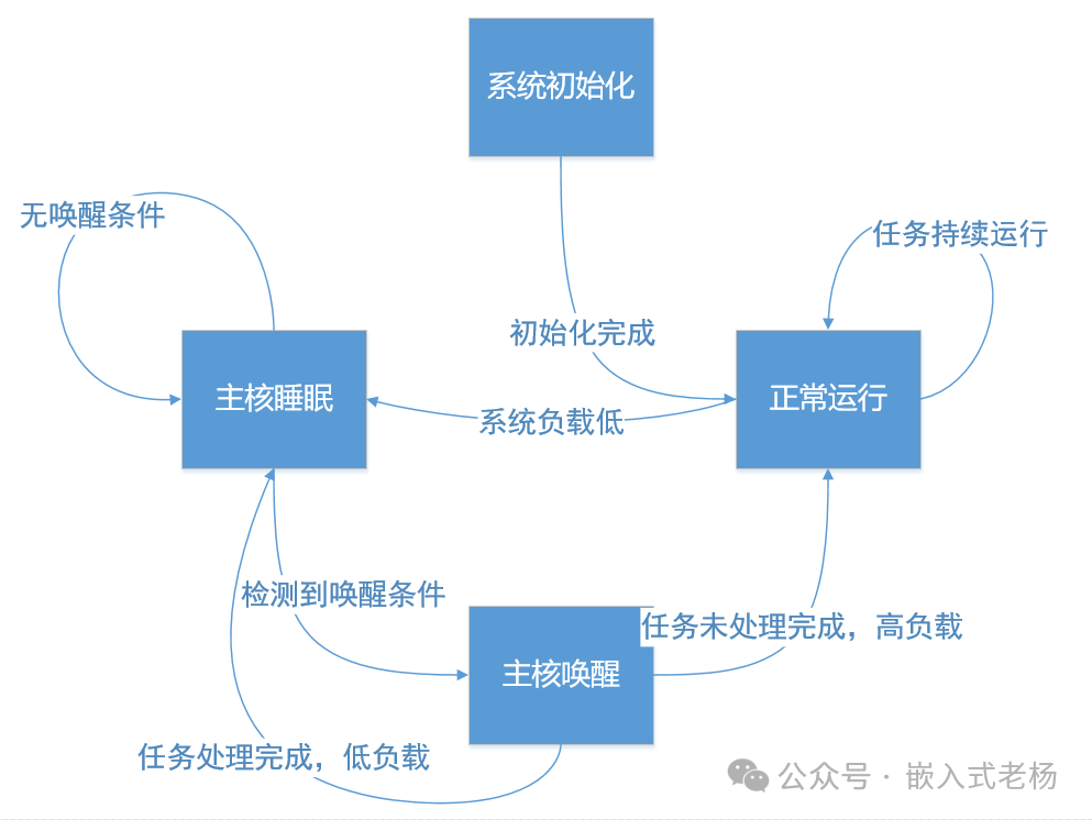
State Machine of the ESP32-S3 Multi-Core Processor
|
State Name |
State Description (CPU0/CPU1 Behavior + ULP Behavior) |
Conditions for Triggering Transition |
|
1. System Initialization |
CPU0: Initializes the system (hardware, peripherals, memory), loads OS, configures CPU1 and ULP; CPU1: Waits for startup, prepares to receive tasks; ULP: Configures the running program and wake-up conditions, on standby. |
Initialization complete → Enter “Normal Operation” state. |
|
2. Normal Operation |
CPU0: Runs OS kernel, processes high-priority tasks (Wi-Fi/Bluetooth, algorithms, etc.), schedules tasks; CPU1: Processes allocated tasks (sensor/motor control, etc.), communicates with CPU0; ULP: On standby, listens for wake-up conditions. |
System load low → Enter “Main Core Sleep” state. |
|
3. Main Core Sleep |
CPU0/CPU1: Enter light/deep sleep, save state to RTC memory, configure ULP wake-up conditions; ULP: Starts running, executes low-power tasks (sensor collection, periodic monitoring), detects wake-up conditions. |
ULP detects wake-up conditions (sensor threshold/timer expiration) → Enter “Main Core Wake-Up” state. |
|
4. Main Core Wake-Up |
CPU0/CPU1: Wake from sleep, restore RTC memory data, process tasks based on ULP information; ULP: Continues low-power tasks (if needed) or goes into standby. |
Task processing complete → If load is low, return to “Main Core Sleep” state; otherwise, return to “Normal Operation” state. |
04
—
Use Cases of Multi-Core Processors
1. Function:
CPU0: Responsible for Wi-Fi connection management, ULP initialization, ADC data collection, and deep sleep management.
CPU1: Responsible for audio data collection and real-time processing.
ULP co-processor: Monitors temperature periodically while the main core is asleep, waking the main core when the temperature exceeds a threshold to achieve low-power operation.
2. Project Directory Structure
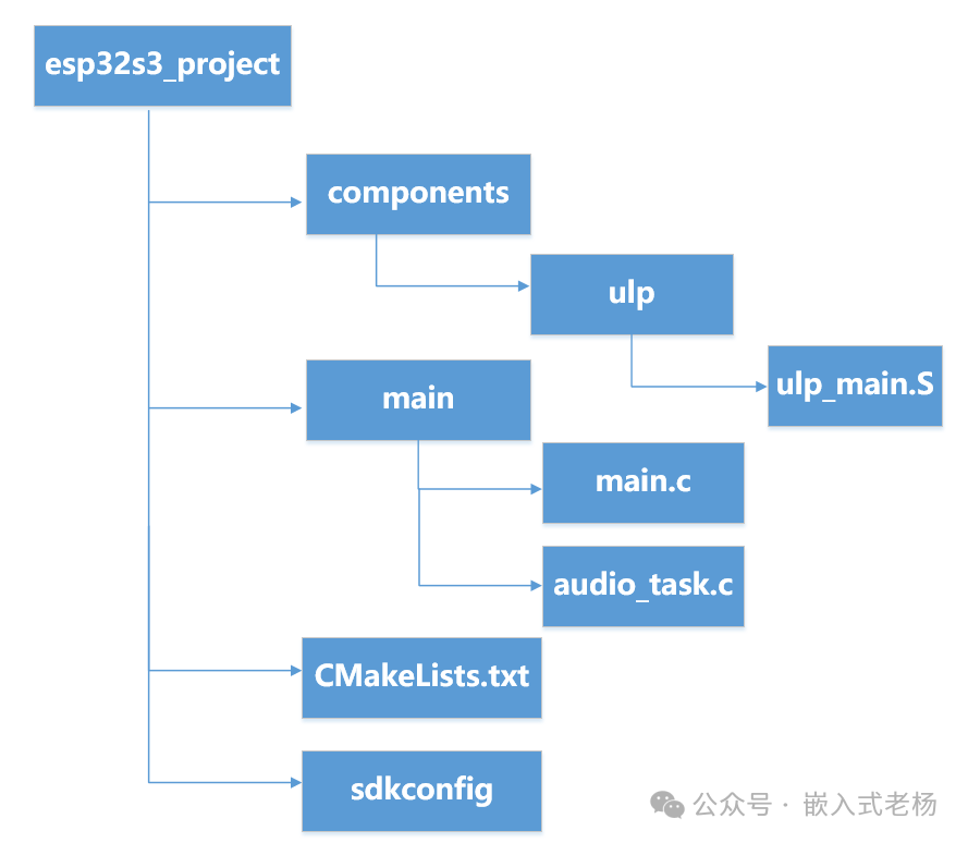
All code (CPU0, CPU1, and ULP) will ultimately be compiled into a single executable file. The entire executable file will be flashed onto the ESP32-S3, and tasks will be allocated to different cores and co-processors based on program logic during runtime.
3. Code
CMakeLists.txt
cmake_minimum_required(VERSION 3.10)include($ENV{IDF_PATH}/tools/cmake/project.cmake)project(esp32s3_project)
# Configure ULPset(ulp_app_name ulp_main)set(ulp_s_sources components/ulp/ulp_main.S)ulp_embed_binary(${ulp_app_name} "${ulp_s_sources}")
# Register components (source files in main directory)idf_component_register(  SRCS "main/main.c" "main/audio_task.c"  INCLUDE_DIRS "main")
main/main.c
#include "freertos/FreeRTOS.h"#include "freertos/task.h"#include "esp_wifi.h"#include "esp_event.h"#include "esp_log.h"#include "nvs_flash.h"#include "driver/adc.h"#include "esp_sleep.h"
static const char *TAG = "wifi_station";
void wifi_event_handler(void* arg, esp_event_base_t event_base, int32_t event_id, void* event_data) {    if (event_base == WIFI_EVENT && event_id == WIFI_EVENT_STA_START) {        esp_wifi_connect();    } else if (event_base == WIFI_EVENT && event_id == WIFI_EVENT_STA_DISCONNECTED) {        esp_wifi_connect();        ESP_LOGI(TAG, "retry to connect to the AP");    } else if (event_base == IP_EVENT && event_id == IP_EVENT_STA_GOT_IP) {        ip_event_got_ip_t* event = (ip_event_got_ip_t*) event_data;        ESP_LOGI(TAG, "got ip: " IPSTR, IP2STR(&event->ip_info.ip));    }}
void wifi_init_sta(void) {    esp_netif_init();    ESP_ERROR_CHECK(esp_event_loop_create_default());    esp_netif_create_default_wifi_sta();
    wifi_init_config_t cfg = WIFI_INIT_CONFIG_DEFAULT();    ESP_ERROR_CHECK(esp_wifi_init(&cfg));
    esp_event_handler_instance_t instance_any_id;    esp_event_handler_instance_t instance_got_ip;    ESP_ERROR_CHECK(esp_event_handler_instance_register(WIFI_EVENT,                                                        ESP_EVENT_ANY_ID,                                                        &wifi_event_handler,                                                        NULL,                                                        &instance_any_id));    ESP_ERROR_CHECK(esp_event_handler_instance_register(IP_EVENT,                                                        IP_EVENT_STA_GOT_IP,                                                        &wifi_event_handler,                                                        NULL,                                                        &instance_got_ip));
    wifi_config_t wifi_config = {        .sta = {            .ssid = "your_ssid",            .password = "your_password",        },    };    ESP_ERROR_CHECK(esp_wifi_set_mode(WIFI_MODE_STA));    ESP_ERROR_CHECK(esp_wifi_set_config(WIFI_IF_STA, &wifi_config));    ESP_ERROR_CHECK(esp_wifi_start());}
extern void ulp_main(void); // Declare ULP entry symbol
void ulp_init(void) {    extern const uint8_t ulp_main_bin_start[] asm("_binary_ulp_main_bin_start");    extern const uint8_t ulp_main_bin_end[] asm("_binary_ulp_main_bin_end");
    ulp_load_binary(0, ulp_main_bin_start, (ulp_main_bin_end - ulp_main_bin_start) / sizeof(uint32_t));    ulp_run(&ulp_main);  // Use ULP entry label}
void app_main(void) {    ESP_ERROR_CHECK(nvs_flash_init());    wifi_init_sta();
    adc1_config_width(ADC_WIDTH_BIT_12);    adc1_config_channel_atten(ADC1_CHANNEL_0, ADC_ATTEN_DB_11);
    // Create CPU1 audio task    xTaskCreatePinnedToCore(        audio_processing_task,  // Task function        "audio_task",           // Task name        4096,                   // Stack size        NULL,                   // Parameters        5,                      // Priority        NULL,                   // Task handle        1                       // Core 1    );
    ulp_init();
    while (1) {        int adc_value = adc1_get_raw(ADC1_CHANNEL_0);        ESP_LOGI(TAG, "ADC Value: %d", adc_value);
        esp_sleep_enable_ulp_wakeup();  // Enable ULP wakeup        esp_deep_sleep_start();         // Enter deep sleep    }}
main/audio_task.c
Audio processing task code:
#include "freertos/FreeRTOS.h"#include "freertos/task.h"#include "driver/i2s.h"#include "esp_log.h"
static const char *TAG = "audio_processing";
#define I2S_NUM I2S_NUM_0#define I2S_SAMPLE_RATE 16000#define I2S_SAMPLE_BITS I2S_BITS_PER_SAMPLE_16BIT
void audio_processing_task(void *pvParameters) {    i2s_config_t i2s_config = {        .mode = I2S_MODE_MASTER | I2S_MODE_RX | I2S_MODE_TX,        .sample_rate = I2S_SAMPLE_RATE,        .bits_per_sample = I2S_SAMPLE_BITS,        .channel_format = I2S_CHANNEL_FMT_ONLY_LEFT,        .communication_format = I2S_COMM_FORMAT_I2S,        .intr_alloc_flags = 0,        .dma_buf_count = 8,        .dma_buf_len = 64,        .use_apll = false,        .tx_desc_auto_clear = false,        .fixed_mclk = 0,    };
    i2s_pin_config_t pin_config = {        .bck_io_num = 26,        .ws_io_num = 25,        .data_out_num = 22,        .data_in_num = 21,    };
    ESP_ERROR_CHECK(i2s_driver_install(I2S_NUM, &i2s_config, 0, NULL));    ESP_ERROR_CHECK(i2s_set_pin(I2S_NUM, &pin_config));
    int16_t audio_buffer[128];    while (1) {        size_t bytes_read;        i2s_read(I2S_NUM, &audio_buffer, sizeof(audio_buffer), &bytes_read, portMAX_DELAY);        // Perform audio processing on audio_buffer        i2s_write(I2S_NUM, &audio_buffer, sizeof(audio_buffer), &bytes_read, portMAX_DELAY);    }}
components/ulp/ulp_main.S
ULP main code:
#include "soc/sens_reg.h"  // Include sensor register definitions#include "soc/rtc_cntl_reg.h"  // Include RTC register definitions#include "ulp_riscv_timer.h"  // ULP timer API
.section .text.global ulp_main
ulp_main:    // Configure ULP timer, wake itself after 10 seconds    li t0, 10000  // 10 seconds (unit: milliseconds, ULP timer defaults to 1kHz clock)    call ulp_riscv_timer_set_wakeup  // Call timer API to set wakeup
    // Read temperature sensor data    li t0, SENS_SAR_TSENS_DATA_REG  // Temperature sensor register address    lw t1, 0(t0)                    // Read raw temperature data    andi t1, t1, 0xFFFF             // Extract low 16 bits of valid data
    // Check if temperature exceeds threshold    li t2, 50  // Threshold    bge t1, t2, wakeup  // If temperature >= threshold, wake main core
    // Not reaching threshold, enter sleep    wfi    j ulp_main  // Repeat execution after timer wakeup
wakeup:    // Write to RTC wakeup register, trigger main core wakeup    li t0, RTC_CNTL_SW_CPU_INT_REG  // Wakeup register address    li t1, RTC_CNTL_SW_CPU_INT_M    // Wakeup mask    sw t1, 0(t0)                    // Trigger wakeupWfi
This article’s case study uses the following hardware and software:
1. SOC Model: ESP32-S3-N16R8;
2. Software Development Environment: ESP-IDF 5.3.1, VSCode IDE (VSCodeUserSetup-x64-1.102.1 version);
3. ESP32 Project Version: IDF version (FreeRTOS);
4. Program Download: Type C USB (USB to Serial) interface;
5. This software and hardware case study is for personal learning only and not for commercial use.
References for this article:
“ESP32-S3 Technical Reference Manual Version 1.7”;
“ESP32-S3 Series Chip Technical Specification Version 2.0”.