In your embedded projects, can the program really respond immediately when a button is pressed?
The seemingly simple “polling” may hide performance traps and response delays; while “interrupts” provide a more elegant and efficient solution. This article will guide you through a classic “button control LED” experiment using
<span>Rust</span>and<span>ESP32-S3</span>, allowing you to intuitively experience the vast differences between the two from a coding perspective, helping you master the core of embedded event handling.
Polling is the action of continuously “polling” or reading the input state, while interrupts allow peripherals to “interrupt” the processor, notifying it that an event has occurred. This demonstration will show how to control the LED’s blinking frequency using both polling and interrupts.
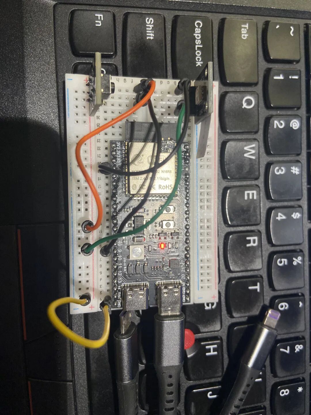
The peripherals used are an LED and a switch button:
-
Connect the LED anode to
<span>gpio4</span>on the development board, and the LED cathode to<span>GND</span>on the development board. -
Connect one end of the button to
<span>gpio9</span>, which will be configured as an input, and the other end to<span>GND</span>on the development board.
Polling to Handle Button Press Events
Using polling to detect button press events (with real-time changing delay) to control the LED’s blinking rate, meaning that each time the button is pressed, the LED will blink at a different rate. In this application, the delay is placed in a loop, continuously polling to check if the button has been pressed.
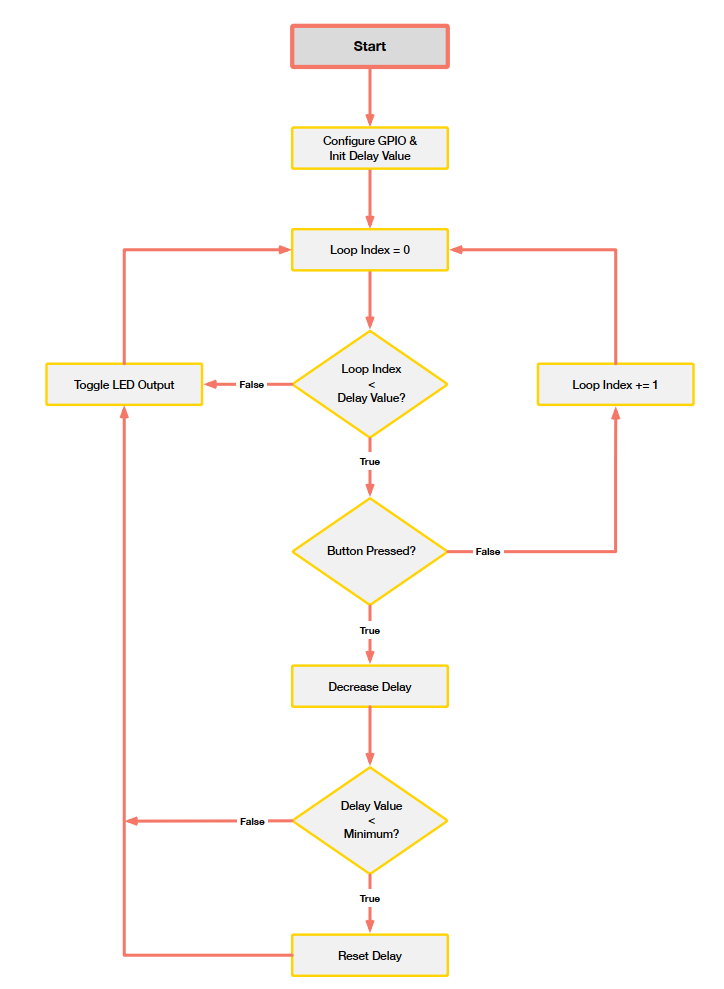
First, after configuring the GPIO pins, initialize a delay value. This value will be used to create a delay through the algorithm. Additionally, the LED output is initialized to a known state (either on or off).
Next, a counter/index is initialized to zero and enters a loop, continuously increasing the count until it reaches the delay value. Within this delay loop, it continuously polls to check if the button has been pressed. If the button is pressed at any time, the delay value will decrease, meaning the LED blinking frequency will increase. However, it is necessary to check the new delay value to ensure it does not become negative. Therefore, if the delay value falls below a certain threshold, it will be reset to the initial value. After that, the LED output state can be toggled, and the delay loop restarts.
If the check for the button press is placed after the delay loop, then when the delay is long, the button press will be missed. This is why interrupts are more convenient. With interrupts, the operation is paused to immediately respond to the button press event.
// Loop
#![no_std]
#![no_main]

use esp_backtrace as _;
use esp_hal::{
    gpio::{Input, InputConfig, Io, Level, Output, OutputConfig, Pull},
    main, timer::timg::TimerGroup,
};
use esp_println::println;

esp_bootloader_esp_idf::esp_app_desc!();

#[main]
fn main() -> ! {
    // Get peripherals toolbox
    let peripherals = esp_hal::init(esp_hal::Config::default());

    // Disable watchdog timer
    let timer_group0 = TimerGroup::new(peripherals.TIMG0);
    let mut wdt0 = timer_group0.wdt;
    wdt0.disable();

    let timer_group1 = TimerGroup::new(peripherals.TIMG1);
    let mut wdt1 = timer_group1.wdt;
    wdt1.disable();

    println!("Watchdog timers disabled!");

    // Create GPIO manager
    let _io = Io::new(peripherals.IO_MUX);

    // Configure LED: set gpio4 as output pin, initial state high
    let mut led = Output::new(peripherals.GPIO4, Level::High, OutputConfig::default());

    let config = InputConfig::default().with_pull(Pull::Up);
    // Configure button: set gpio9 as input pin and enable internal pull-up resistor
    let button = Input::new(peripherals.GPIO9, config);
    println!("button level {:?} - {:?} - {:#?}", button.is_low(), button.is_high(), button.level());

    // Create a mutable delay variable, initial value is large, representing initial slow blinking speed
    // Software Delay: Achieved by letting the CPU execute a time-consuming loop.
    // This method is simple but inefficient, as the CPU is completely "idling" during the delay, unable to do anything else.
    let mut blinkdelay = 1_000_000_u32;

    // First turn off the LED to ensure initial state consistency
    led.set_low();

    // Enter main loop
    loop {
        // This is a software delay loop. It will idle `blinkdelay` times.
        // During this delay, it continuously checks the button state.
        for _i in 1..blinkdelay {
            // println!("{} - Button: {}", i, button.is_low());
            // is_low() checks if the button is pressed (since we connected to GND and used a pull-up resistor)
            if button.is_low() {
                println!("Button pressed!");

                // If pressed, reduce the delay value to make the next blink faster
                blinkdelay = blinkdelay - 25_000_u32;
                // If the delay value becomes too small, reset it back to the initial large value to achieve cycling speed
                if blinkdelay < 25_000 {
                    blinkdelay = 1_000_000_u32;
                }
            }
        }
        // After the delay loop ends (i.e., after a period of time), toggle the LED's state
        led.toggle();
    }
}
Execute command:<span>cargo run</span> or <span>cargo build</span> and <span>espflash flash target/xtensa-esp32s3-none-elf/debug/esp32s3-demo</span> results:
[2025-08-02T09:18:55Z INFO ] Serial port: 'COM4'
[2025-08-02T09:18:55Z INFO ] Connecting...
[2025-08-02T09:18:56Z INFO ] Using flash stub
Chip type:         esp32s3 (revision v0.2)
Crystal frequency: 40 MHz
Flash size:        16MB
Features:          WiFi, BLE, Embedded Flash
MAC address:       10:51:db:85:14:b4
App/part. size:    86,736/16,384,000 bytes, 0.53%
[00:00:00] [========================================]      14/14      0x0      Skipped! (checksum matches)
[00:00:00] [========================================]       1/1       0x8000   Skipped! (checksum matches)
[00:00:00] [========================================]      22/22      0x10000  Skipped! (checksum matches)
[2025-08-02T09:18:56Z INFO ] Flashing has completed!
Commands:
    CTRL+R    Reset chip
    CTRL+C    Exit

ESP-ROM:esp32s3-20210327
Build:Mar 27 2021
rst:0x15 (USB_UART_CHIP_RESET),boot:0x8 (SPI_FAST_FLASH_BOOT)
Saved PC:0x40378cab
SPIWP:0xee
mode:DIO, clock div:2
load:0x3fce2810,len:0x15a0
load:0x403c8700,len:0x4
load:0x403c8704,len:0xd24
load:0x403cb700,len:0x2f04
entry 0x403c8928
I (27) boot: ESP-IDF v5.4.1-426-g3ad36321ea 2nd stage bootloader
I (27) boot: compile time Apr 24 2025 15:55:11
I (28) boot: Multicore bootloader
I (29) boot: chip revision: v0.2
I (32) boot: efuse block revision: v1.3
I (35) boot.esp32s3: Boot SPI Speed : 40MHz
I (39) boot.esp32s3: SPI Mode       : DIO
I (43) boot.esp32s3: SPI Flash Size : 16MB
I (47) boot: Enabling RNG early entropy source...
I (51) boot: Partition Table:
I (54) boot: ## Label            Usage          Type ST Offset   Length
I (60) boot:  0 nvs              WiFi data        01 02 00009000 00006000
I (67) boot:  1 phy_init         RF data          01 01 0000f000 00001000
I (73) boot:  2 factory          factory app      00 00 00010000 00fa0000
I (80) boot: End of partition table
I (83) esp_image: segment 0: paddr=00010020 vaddr=3c000020 size=04f84h ( 20356) map
I (95) esp_image: segment 1: paddr=00014fac vaddr=3fc89194 size=00658h (  1624) load
I (98) esp_image: segment 2: paddr=0001560c vaddr=40378000 size=01194h (  4500) load
I (107) esp_image: segment 3: paddr=000167a8 vaddr=00000000 size=09870h ( 39024)
I (122) esp_image: segment 4: paddr=00020020 vaddr=42010020 size=05280h ( 21120) map
I (128) boot: Loaded app from partition at offset 0x10000
I (128) boot: Disabling RNG early entropy source...
button level false - true - High
Will the button state remain low?
No, because a momentary button is used here, not a toggle switch, and the button will return to high when released.
Button state change process:
-
Initial state (not pressed):
GPIO9 ← Pull-up resistor ← 3.3V GPIO9 ← Button (open) ← GND Result: GPIO9 = High (3.3V) button.is_low() = false -
Button pressed (finger held down):
GPIO9 ← Pull-up resistor ← 3.3V GPIO9 ← Button (closed) ← GND Result: GPIO9 = Low (0V) - GND path takes priority button.is_low() = true -
Button released (finger lifted):
GPIO9 ← Pull-up resistor ← 3.3V
GPIO9 ← Button (open) ← GND

Result: GPIO9 = High (3.3V) - controlled again by the pull-up resistor
button.is_low() = false
Code representation:
for _i in 1..blinkdelay {
    if button.is_low() {  // Only true when "held down"
        println!("Button pressed!");
        blinkdelay = blinkdelay - 25_000_u32;
    }
}
Timing analysis:
| Timeline | 0ms | 100ms | 200ms | 300ms | 400ms |
|---|---|---|---|---|---|
| Button | Not pressed | Pressed | Held | Held | Released |
| State | High | Low | Low | Low | High |
| Delay Time | 1M | Rapidly decreasing | Very small | Very small | Maintaining small value |
| LED Frequency | Slow blink | Accelerating | Very fast | Very fast | Very fast |
| Human Eye Perception | Blinking | Blinking | Constantly on | Constantly on | Fast blink |
[Constantly On] explanation:
According to the delay calculation display, continuous reduction may cause the delay time value to far exceed the initial value range, due to the overflow characteristics of the u32 type affecting the actual value change process. When the delay time continues to decrease, once it reaches 0, it will wrap around to a very large positive value. This overflow mechanism will cause the delay time not to be reset but to remain in a very large value range. When the button is pressed continuously, the counter will continue to calculate in an unexpected way, avoiding the expected reset behavior. The result is that the LED switching becomes extremely slow, and it actually appears to stop blinking completely.
Why does this happen?
1. Role of the pull-up resistor:
-
When the button is open, the pull-up resistor ensures that GPIO9 always has a clear high signal
-
Prevents the pin from floating, leading to an uncertain state
2. Characteristics of momentary buttons:
-
The button only closes under mechanical pressure
-
Automatically returns to the open state when there is no pressure
-
This is the most common type of button
3. Circuit priority:
-
When the button is closed, the GND path resistance is almost 0, much smaller than the pull-up resistor
-
According to Ohm’s law, current chooses the path with the least impedance
-
So when pressed, GPIO9 is pulled to 0V
Conclusion is that the button state is low only during the physical press, and immediately returns to high after release. This is standard momentary button behavior.
Interrupt Handling for Button Press Events
Next, we will build an application that uses interrupts to detect and monitor button press events. The steps to configure interrupts are as follows in the code.
To avoid spending too much time inside the ISR, set a flag (G_FLAG) inside the ISR, and let the main thread check this flag. It is important to know that spending time in the ISR will affect the execution progress of the <span>main</span> function or other code.
// Interrupt
#![no_std]
#![no_main]

use esp_backtrace as _;
use esp_hal::{
    gpio::{Event, Input, InputConfig, Io, Level, Output, OutputConfig, Pull},
    handler, main,
};
use core::sync::atomic::{AtomicU32, Ordering};
use core::cell::{Cell, RefCell};
use critical_section::Mutex;
use esp_println::println;

esp_bootloader_esp_idf::esp_app_desc!();

// Used to share pin instance between ISR and main to clear interrupt flag in ISR
static G_PIN: Mutex<RefCell<Option<Input>>> = Mutex::new(RefCell::new(None));
// Used to pass the "button pressed" event flag between ISR and main
static G_FLAG: Mutex<Cell<bool>> = Mutex::new(Cell::new(false));
// Global variable: used to store blink delay, AtomicU32 is a thread-safe integer type
static BLINK_DELAY: AtomicU32 = AtomicU32::new(500); // Initial delay 500ms

#[handler] // This is an interrupt handler function
fn gpio_handler() {
    // Enter critical section, only do necessary hardware operations
    critical_section::with(|cs| {
        // Clear interrupt flag - this is a necessary hardware operation
        G_PIN.borrow_ref_mut(cs).as_mut().unwrap().clear_interrupt();
        // Set flag to notify main loop
        G_FLAG.borrow(cs).set(true);
    });
    // ISR ends - total execution time should be in microseconds
}

#[main]
fn main() -> ! {
    // Get peripherals toolbox
    let peripherals = esp_hal::init(esp_hal::Config::default());

    // Create GPIO manager
    let mut io = Io::new(peripherals.IO_MUX);
    // 1. Register interrupt handler
    io.set_interrupt_handler(gpio_handler);
    println!("GPIO interrupt handler registered");

    // Configure LED: set gpio4 as output pin, initial state high
    let mut led = Output::new(peripherals.GPIO4, Level::High, OutputConfig::default());

    let config = InputConfig::default().with_pull(Pull::Up);

    // 2. Configure pin as input
    // Configure button: set gpio9 as input pin and enable internal pull-up resistor
    let mut button = Input::new(peripherals.GPIO9, config);
    println!("button level {:?} - {:?} - {:#?}", button.is_low(), button.is_high(), button.level());
    // 3. Listen for falling edge events
    button.listen(Event::FallingEdge);

    // 4. Move configured pin into global variable
    critical_section::with(|cs| G_PIN.borrow_ref_mut(cs).replace(button));

    let mut delay = esp_hal::delay::Delay::new();

    // Enter main loop
    loop {
        // After the delay loop ends (i.e., after a period of time), toggle the LED's state
        led.toggle();

        // Get the current delay value
        let current_delay = BLINK_DELAY.load(Ordering::Relaxed);
        // Hardware delay
        delay.delay_millis(current_delay);

        critical_section::with(|cs| {
            if G_FLAG.borrow(cs).get() {
                // Clear global flag
                G_FLAG.borrow(cs).set(false);

                // Modify delay value
                let mut new_delay = BLINK_DELAY.load(Ordering::Relaxed);
                new_delay = if new_delay <= 100 { 500 } else { new_delay - 100 };
                BLINK_DELAY.store(new_delay, Ordering::Relaxed);
                esp_println::println!("Delay changed to: {}", new_delay);
            }
        });
    }
}
Successfully executed command:<span>cargo run</span>, results as follows:
[2025-08-02T08:36:15Z INFO ] Serial port: 'COM3'
[2025-08-02T08:36:15Z INFO ] Connecting...
[2025-08-02T08:36:16Z INFO ] Using flash stub
Chip type:         esp32s3 (revision v0.2)
Crystal frequency: 40 MHz
Flash size:        16MB
Features:          WiFi, BLE, Embedded Flash
MAC address:       10:51:db:85:14:b4
App/part. size:    87,808/16,384,000 bytes, 0.54%
[00:00:00] [========================================]      14/14      0x0      Skipped! (checksum matches)
[00:00:00] [========================================]       1/1       0x8000   Skipped! (checksum matches)
[00:00:02] [========================================]      24/24      0x10000  Verifying... OK!
[2025-08-02T08:36:19Z INFO ] Flashing has completed!
Commands:
    CTRL+R    Reset chip
    CTRL+C    Exit

ESP-ROM:esp32s3-20210327
Build:Mar 27 2021
rst:0x1 (POWERON),boot:0x8 (SPI_FAST_FLASH_BOOT)
SPIWP:0xee
mode:DIO, clock div:2
load:0x3fce2810,len:0x15a0
load:0x403c8700,len:0x4
load:0x403c8704,len:0xd24
load:0x403cb700,len:0x2f04
entry 0x403c8928
I (30) boot: ESP-IDF v5.4.1-426-g3ad36321ea 2nd stage bootloader
I (30) boot: compile time Apr 24 2025 15:55:11
I (30) boot: Multicore bootloader
I (32) boot: chip revision: v0.2
I (34) boot: efuse block revision: v1.3
I (38) boot.esp32s3: Boot SPI Speed : 40MHz
I (42) boot.esp32s3: SPI Mode       : DIO
I (46) boot.esp32s3: SPI Flash Size : 16MB
I (49) boot: Enabling RNG early entropy source...
I (54) boot: Partition Table:
I (57) boot: ## Label            Usage          Type ST Offset   Length
I (63) boot:  0 nvs              WiFi data        01 02 00009000 00006000
I (69) boot:  1 phy_init         RF data          01 01 0000f000 00001000
I (76) boot:  2 factory          factory app      00 00 00010000 00fa0000
I (82) boot: End of partition table
I (86) esp_image: segment 0: paddr=00010020 vaddr=3c000020 size=053d0h ( 21456) map
I (98) esp_image: segment 1: paddr=000153f8 vaddr=3fc89194 size=0066ch (  1644) load
I (101) esp_image: segment 2: paddr=00015a6c vaddr=40378000 size=01194h (  4500) load
I (109) esp_image: segment 3: paddr=00016c08 vaddr=00000000 size=09410h ( 37904)
I (125) esp_image: segment 4: paddr=00020020 vaddr=42010020 size=056b8h ( 22200) map
I (131) boot: Loaded app from partition at offset 0x10000
I (131) boot: Disabling RNG early entropy source...
GPIO interrupt handler registered
button level false - true - High
Delay changed to: 400
Delay changed to: 300
Delay changed to: 200
Delay changed to: 100
Delay changed to: 500
Delay changed to: 400
The “Delay changed to” in the log above is the output when the button is manually pressed, decreasing from 500 milliseconds to 100 milliseconds and then starting to decrease from 500 milliseconds again, while the LED’s blinking frequency will also increase as the delay decreases.
In the code, we placed the time-consuming delay operation and LED control in the main loop, while the quick button event detection task is handled by interrupts. The main loop no longer needs to actively poll the button, it only needs to check the flag left by the interrupt. In contrast, the interrupt operation is much more efficient than the pure polling scheme.
Project address:
https://github.com/fruzly/no_std-training/intro/esp32s3-demo
Code files for this article:04_blinky_interrupte.rs and 04_blinky_loop.rs