

The wake-up source comes from the network message of the ECU node itself, which can be in a completely sleep state, generally consuming no energy. The characteristic of this wake-up is that only when the CAN transceiver detects a change in bus level or a specific message will it activate the CAN chip INH pin to control the LDO to power the main control chip, thus waking up the ECU node. The SIT1043 CAN transceiver from Chiplink supports both wake-up functions mentioned above; let’s briefly introduce the SIT1043.
1
SIT1043Function Overview
SIT1043 is a high-speed CAN transceiver that provides an interface between the controller area network (CAN) protocol controller and the physical two-wire CAN bus. The SIT1043 belongs to Chiplink’s third-generation high-speed CAN transceivers, which shows significant improvements compared to the first-generation SIT1040 and the second-generation SIT1042 devices. The SIT1043 implements the CAN physical layer defined in the current ISO1189-2:2016 standard, including the latest timing parameters for defining loop delay symmetry. It offers improved electromagnetic compatibility (EMC) performance, ultra-low power consumption, and passive performance when the power supply voltage is off. Its features also include:
❶ Low power management controls the power supply of the entire node, supports local and remote wake-up, and has wake-up source identification capabilities;
❷ Various protection and diagnostic functions, including bus line short-circuit detection and battery connection detection;
❸ Can be directly connected to microcontrollers with a power supply voltage of 3V to 5V.
If a high-speed CAN network is required where nodes need to be on standby at all times (even when internal VIO and VCC power supplies are off), especially for battery-powered systems, managing these functions makes the SIT1043 an ideal choice.
2
SIT1043Package and Pin Description
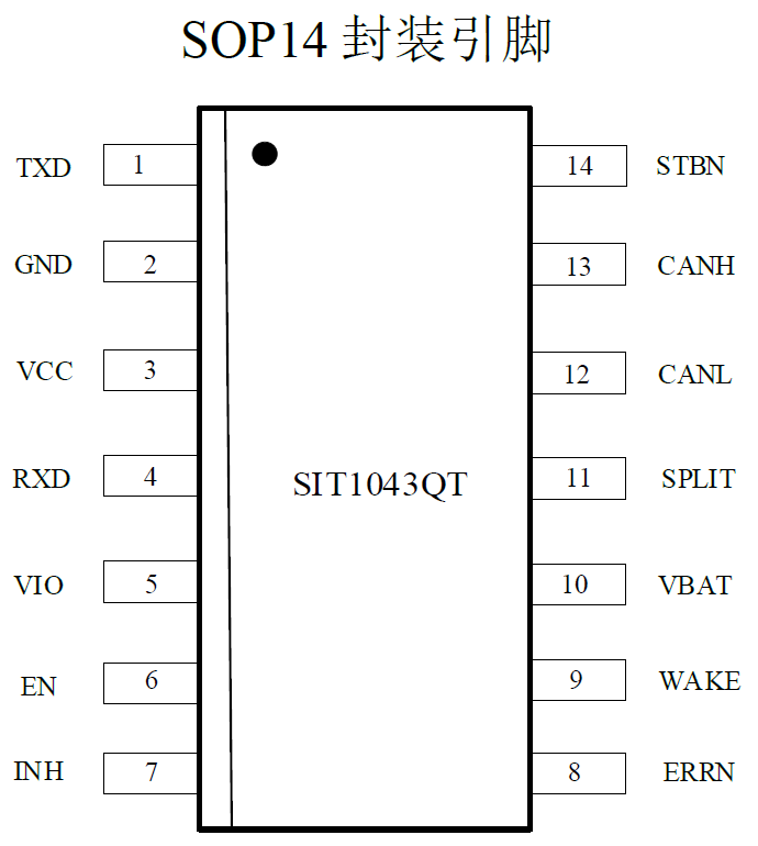
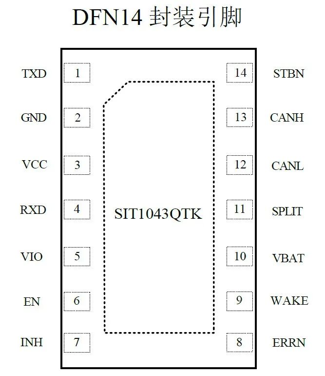
Figure 1: SIT1043 Two Package Types
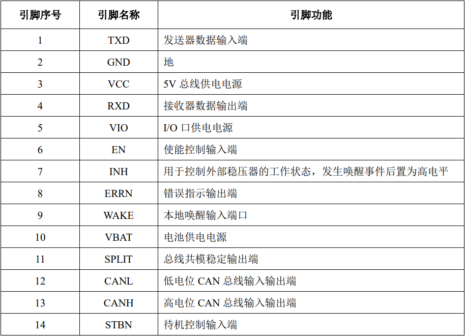
Figure 2:SIT1043 Pin Function Description
3
SIT1043 Chip Characteristics

Figure 3:SIT1043 Characteristics
4
SIT1043 Low Power Mode
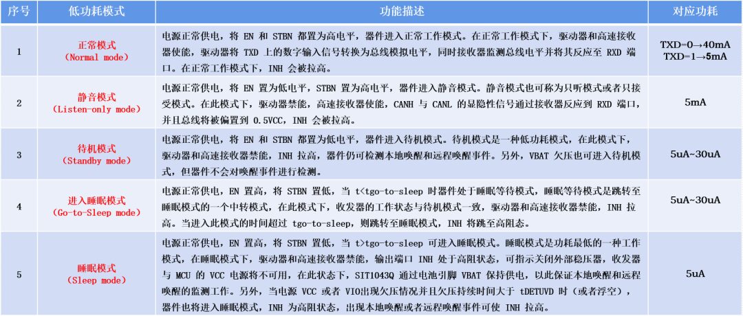
Figure 4:SIT1043 Five Low Power Modes and Power Consumption
5
SIT1043 Fault Diagnosis and Status Flags
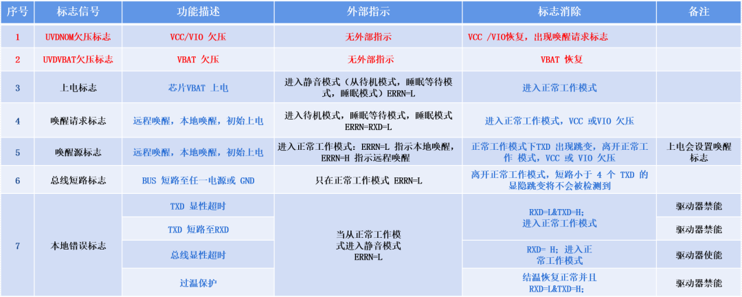
Figure 5: SIT1043 Status Flags and Corresponding Fault Indication
SIT1043 Typical Control Applications
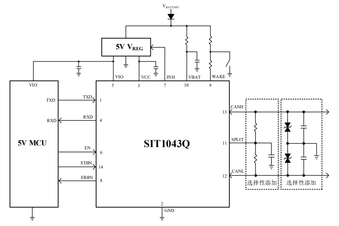
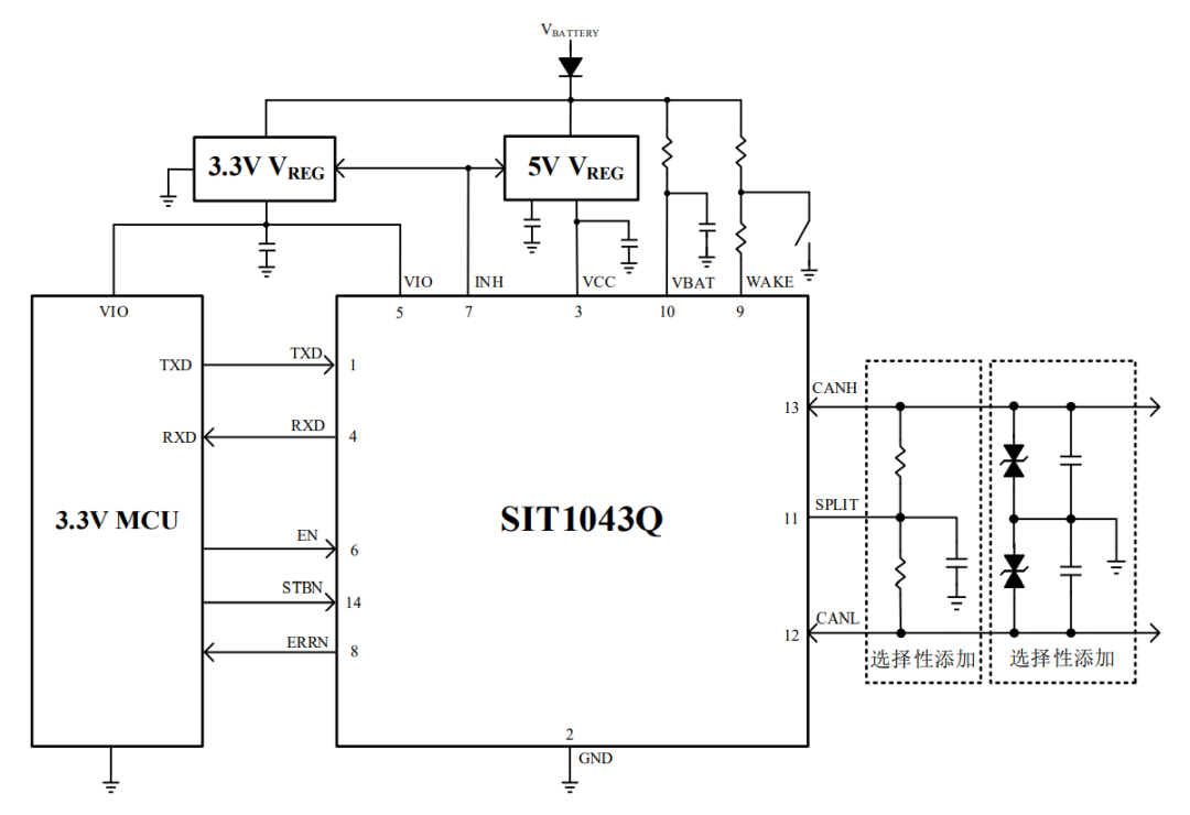
Figure 6: SIT1043 Typical 5V and 3.3V System Control Application Diagram
Typical Applications of SIT1043 CAN Transceiver in Automotive ECU
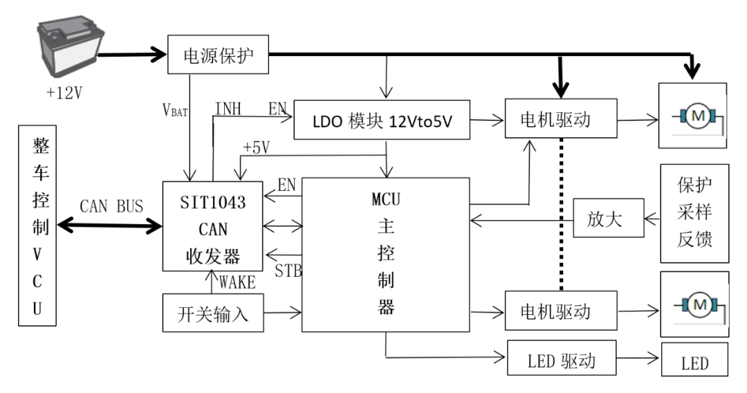
Figure 7: Automotive Door Circuit Control System Block Diagram