Application of Resistive Strain Sensors Based on Proteus Electronic Scale
1. Objective
① Understand the basic principles and usage methods of resistive strain sensors.
② Comprehend the components and principles of electronic scales
③ Improve the sensitivity of the sensor
2. Basic Principles
The electronic scale uses a strain gauge sensor to convert the weight of an object (non-electrical signal) into an electrical signal. When an object is placed on the electronic scale, the elastic element of the scale deforms, and the strain gauge attached to the elastic element also deforms, resulting in a change in the resistance value of the strain gauge. By measuring the circuit, the change in resistance is converted into a voltage or current signal, which is amplified and processed to display the weight of the object on the screen.
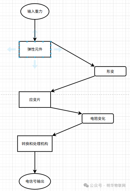
Figure 1: Working Principle of Electronic Scale
3. Circuit Composition
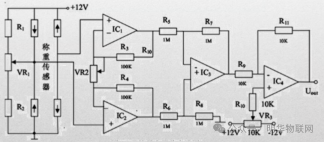
The circuit structure of the strain gauge sensor in the electronic scale includes not only the core Wheatstone bridge but also the power supply circuit, signal amplification circuit, filtering circuit, analog-to-digital conversion circuit, and microprocessor circuit.
1. Weighing Sensor Part
The weighing sensor forms a bridge circuit with R1, R2, and VR1. When the weighing sensor is subjected to force, its internal resistance value changes, breaking the balance of the bridge and outputting a weak voltage signal related to the weight.
2. Signal Amplification Circuit
Pre-amplification: The differential amplifier circuit is composed of IC1 and IC2. VR2 can be used to adjust the amplification factor or circuit balance. R3 and R4 work with IC1 and IC2 to perform initial amplification of the weak differential signal output from the weighing sensor, increasing the signal amplitude for subsequent processing.
Intermediate amplification: IC3, along with R5, R6, R7, and R8, forms a non-inverting amplifier circuit to further amplify the signal and enhance signal strength.
Output amplification: IC4, together with R9, R10, R11, and VR3, forms an inverting amplifier circuit to process the signal again, adjusting the signal amplitude and polarity, ultimately outputting a voltage signal Uout suitable for collection or display. VR3 can be used for fine-tuning the output signal size.
3. Power Supply Section
The circuit is powered by a 12V power supply, providing the necessary voltage for the operational amplifiers to ensure their normal operation.
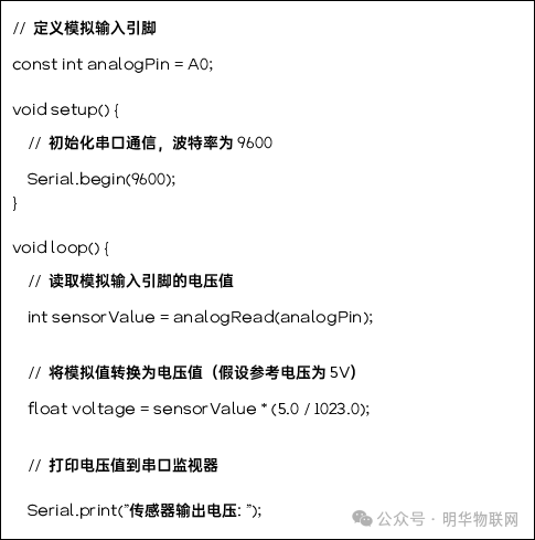
4. Experimental Code