
Introduction
In the failures of medical equipment, issues often arise from certain key chips, leading to abnormal control signals and erratic device actions. In these situations, the oscilloscope becomes a powerful tool, allowing for the rapid identification of key signals and the localization of the root problem.
This article analyzes a fault repair case of the SOMATOM Plus 4 gantry FC CT and discusses the application techniques of the oscilloscope in fault repair for reference.
After starting the SOMATOM Plus 4 gantry FC CT, the machine shows signs of startup, but it cannot perform a check-up or load the gantry scanning parameters, resulting in a braking phenomenon and reporting error codes “RTC_28/RTC_23”. According to the maintenance manual, RTC (Ro-tation Ctrl) refers to the rotation control unit.
Opening the side cover of the CT, the layout of the internal modules can be seen, as shown in Figure 1. Based on the fault phenomenon, it is initially judged that the E301 module (scanning control unit) has failed.
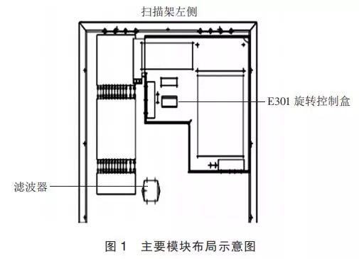
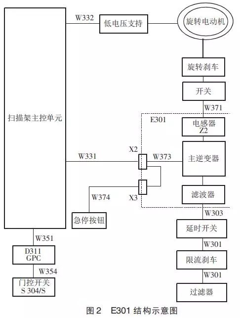
Figure 2 shows the structural diagram of the E301 module. It was found that the yellow indicator light in the E301 module was flashing, specifically in a pattern of 6 cycles. Next, the magnetic levitation motor connection at the X3 interface was checked. The output from E301 to the X3 interface was measured, and the resistance value of the stator coil at X3 was balanced, consistent with the nominal parameters. After powering off, the gantry was pushed to check for resistance and stability. The gantry should be stable enough to be pushed to any angle by hand without locking, and the resistance should be balanced. Since the magnetic block is a balancing support unit for the frame, if it falls off, pushing it by hand will encounter significant resistance; if it moves smoothly, it indicates that it has not fallen off, and the overload of E301 caused by the magnetic block falling off can be ruled out.
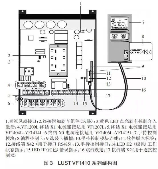
The measured input three-phase AC voltage was 400 V, normal and stable. Opening the E301 inverter (also known as the motor servo), the AC/DC three-phase rectifier’s DC output was measured at 500 V, which is normal. Next, the variable frequency drive and high-frequency thyristor (insulated gate bipolar transistor, IGBT) were checked. The measurement of the IGBT had to be done offline, preferably using a mechanical meter to simulate the diode characteristics of the triggering conduction. The servo (model LUST VF1410HF, maximum output power 42 kW, manufactured by LTI in Germany, circuit shown in Figure 3) was removed, and testing revealed that the IGBT had been broken down. The IGBT model is SKM40GD123D, with a maximum current of 40 A and a maximum voltage of 1200 V.
This type of high-power frequency conversion module, SKM40GD123D, is generally produced by European and Japanese manufacturers. If ordered domestically, the price is expensive, and with such high-power components breaking down, the unit driving the IGBT may also have issues, especially the group that broke down.
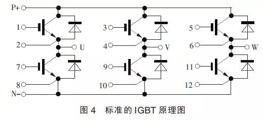
Figure 4 shows the standard IGBT schematic diagram. P&N is the input of the DC bus, which, after modulation of the control signal, outputs high-frequency AC power to the motor windings, controlling the motor’s speed, starting time, and torque by changing the frequency and voltage parameters.
Based on the analysis above, it can be determined that the IGBT is damaged and needs to be replaced. Next, the cause of the breakdown must be identified.
There are many transistors and diodes in the inverter’s IGBT drive circuit that have been broken down. Looking for IC data, replace with the same brand and model. These ICs are rare models that need to be specially ordered and are all surface-mounted packages that require heating and soldering with a hot air station. Pay attention to temperature and time during soldering. After soldering the IC and replacing the IGBT, testing was performed on the machine. Upon startup, the gantry moved, but there was slight vibration during startup, and the check-up test passed. However, when testing at the fastest single circle and braking, it was found that the gantry would reset, and the inverter (FC) would also flash 6 times. In response to this phenomenon, a clamp meter was connected to detect the current at the output of the FC.
At this point, the machine’s error information mentioned the A20 data table for starting parameters. A20 is the parameter setting for RTC, restoring factory parameters and then burning them to the FC control board in hopes of improving the working state of the FC, but the fault persisted. Continued checking of the FC, removing it to measure the IGBT and drive circuit, showed the IGBT was intact, but the drive circuit IC was broken down.
The CPU drive signal of the FC is a pulse width modulation (PWM) square wave with a frequency of 0~8 kHz. The variable frequency drive part is a power electronic system that utilizes solid-state electronic devices. Most variable frequency drives are AC/DC converters, with both input and output being AC voltage. When using a common DC power supply or solar energy, a DC/AC converter architecture is employed. The AC/DC converter can be divided into three parts: the rectifier converting AC to DC, the DC link, and the inverter converting DC back to AC, among which the voltage-source inverter (VSI) is the most common.
The rectifier used by the voltage-source inverter is typically a three-phase, six-step pulse, full-wave rectifying diode bridge, with its DC link including a large-capacity capacitor that smooths the ripple of the DC output and provides stable voltage input to the subsequent inverter. The input power factor of the voltage-source inverter is higher than that of current-source inverters or load commutation inverters, and its distortion is also lower. The inverter can also be configured to convert single-phase AC into three-phase AC.
There are many ways for the inverter to drive the motor, the simplest being U/f scalar control, where the output voltage and output frequency of the inverter are proportional, suitable for constant torque loads. For example, for a 460 V, 60 Hz motor, the ratio of voltage to frequency is 460/60=7.67, and the relationship between voltage and frequency is called the U/f curve. Some U/f controlled inverters have output voltage and frequency that are proportional to the square of each other or have multiple programmable U/f curves. U/f control can be used in many simple applications, but it is not suitable for higher-order applications that require low-speed high torque, dynamic speed adjustment, position control, or torque control. The other two commonly used drive technologies are vector control and direct torque control, which adjust the output voltage’s magnitude and angle based on output current and motor speed, with the aim of precisely controlling the motor’s magnetic flux and torque.
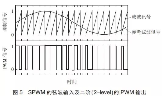
The output of the inverter is achieved using PWM to output AC voltage, among which sinusoidal pulse width modulation (SPWM) is the most direct way to adjust the motor’s voltage and frequency. In Figure 5, there are reference sine wave signals and sawtooth carrier signals that can be adjusted in size and frequency. If the reference signal exceeds the carrier, a high potential is output; conversely, a low potential is output, thus generating a pulse width output signal that varies with time. After filtering, the output signal approaches a sine wave. Besides SPWM, there are other PWM methods, with space vector pulse width modulation (SVPWM) gaining increasing popularity.
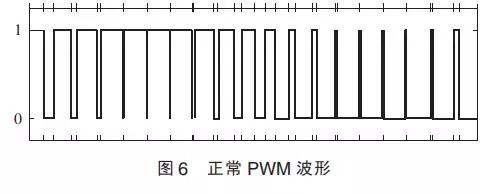
Having understood the drive methods, we began to focus on the drive signal. Using the oscilloscope, we tested the P&N of the DC bus in isolation. The standby signal waveform emitted by the CPU is amplified to each group of square waves by two HC08* chips. One group of square waves showed significant differences, and Figure 6 shows the normal waveform.
After replacing the abnormal HC08* chip with the same brand and model, testing on the machine was performed, and the RTC voltage and current across phases remained balanced. Finally, a complete check-up was performed, loading the fastest single circle scanning protocol, passing the test, and the CT was operating normally.
Similar faults are difficult to locate. Generally, for motion control-related modules, such as variable frequency drives, maintenance must start from the source of the drive waveform, using tools such as oscilloscopes and logic analyzers to check for signal anomalies, thus determining the cause of the abnormalities. Additionally, when replacing components, it is advisable to select original factory models and avoid using substitute models.
[References]
[1] Li Yongzhong. CT Clinical Application Shows Advantages After 40 Years. Liuzhou Medical, 2013, 26(4): 245-247.
[2] Zheng Peiyuan. Electronic Circuits and Electronic Devices. Beijing: Higher Education Press, 2000: 34-38.
[3] He Jinsheng, Wang Hao, Wang Jie. Two Cases of Toshiba Aquilion 16-Row CT Fault Repair. Medical Equipment, 2013, 34(11): 138.
[4] Xu Xiaolei, Li Peixiu. Repair and Analysis of Siemens BIOGRAPH 64 PET/CT Fault. Medical Equipment, 2013, 34(10): 144-145.
[5] Zheng Yu. Basic Basis and Common Methods for CT Fault Finding. Science and Technology Innovation Herald, 2013(24): 7.
【Statement】The source of this article is collected from the internet, author: Zhao Huadong, and does not represent the views of this subscription account nor is responsible for its authenticity. If there are any copyright issues with the content, please contact us immediately, and we will take appropriate measures promptly.
END
Want to learn more about imaging maintenance knowledge?
What are you waiting for?
Quickly scan the code to join the group!


Click the original text for more valuable information!