1. Overview
The positioning instructions in Mitsubishi PLCs (Programmable Logic Controllers) are core functions for achieving precise position control, widely used in automated production lines, CNC machine tools, robotics, and other fields. By controlling servo motors or stepper motors through pulse output, various motion control needs can be met, ranging from simple point control to complex multi-axis coordination. This article will detail the commonly used positioning instructions in Mitsubishi PLCs, including DRVI (Relative Positioning), DRVA (Absolute Positioning), PLSV (Variable Speed Pulse Output), and ZRN (Homing), along with examples to illustrate their application methods.
2. Detailed Explanation of Common Positioning Instructions
2.1 DRVI (Relative Positioning Instruction)
The DRVI (Relative Positioning) instruction is used to achieve relative positioning control, which means moving a specified distance from the current position. Its instruction format is:
plaintext
DRVI S1 S2 D1 D2
Where:
- S1: Relative position (pulse count), a positive number indicates forward rotation, while a negative number indicates reverse rotation.
- S2: Speed (Hz), sets the motor running speed.
- D1: Pulse output port (e.g., Y0, Y1, etc., high-speed pulse output ports).
- D2: Direction output port.
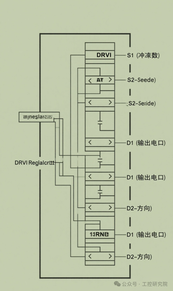
Working Principle: When the DRVI instruction is executed, the PLC will start from the current position and output S1 pulses at the speed set by S2, controlling the motor to move the corresponding distance. The formula for calculating the pulse count is:
plaintext
Pulse Count = Target Position – Current Position
Application Scenarios: Suitable for situations where movement is required relative to the current position, such as material handling, position adjustment, etc.
Notes:
- Must use transistor output type PLC.
- The pulse output port must be configured for high-speed output mode.
- The direction is automatically determined by the sign of S1, and D2 does not need to be controlled separately.
2.2 DRVA (Absolute Positioning Instruction)
The DRVA (Absolute Positioning) instruction is used to achieve absolute positioning control, which means moving to an absolute position relative to the origin. Its instruction format is:
plaintext
DRVA S1 S2 D1 D2
The parameter meanings are the same as DRVI, but S1 represents the absolute position relative to the origin.
Working Principle: The DRVA instruction calculates the pulse count based on the difference between the target position set by S1 and the current position, allowing the motor to move to the target position. The formula for calculating the pulse count is:
plaintext
Pulse Count = Target Position – Current Position
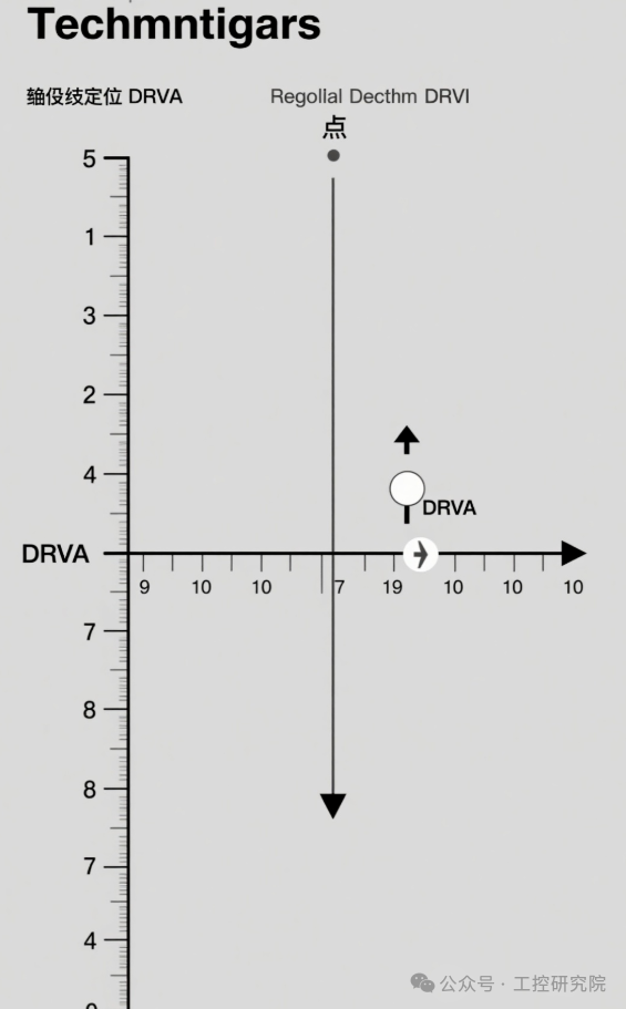
Main Differences Between DRVA and DRVI:
- DRVA uses absolute positions based on the origin.
- DRVI uses relative positions based on the current position.
- DRVA has a position memory function, retaining position information even after power loss.
- DRVI has no position memory; position information is lost after power loss.
Application Scenarios: Suitable for situations requiring precise positioning to a fixed location, such as machining centers, automated assembly lines, etc.
2.3 PLSV (Variable Speed Pulse Output Instruction)
The PLSV (Variable Speed Pulse Output) instruction is used to achieve variable speed pulse output, allowing real-time changes to the output frequency. Its instruction format is:
plaintext
PLSV S1 D1 D2
Where:
- S1: Output frequency (Hz), can be positive or negative; the sign determines the direction.
- D1: Pulse output port.
- D2: Direction output port.
Working Principle: The PLSV instruction outputs pulses at the frequency corresponding to the value of S1 in real-time. By changing the value of S1, speed can be adjusted in real-time. When S1 is positive, D2 outputs ON; when S1 is negative, D2 outputs OFF.
Acceleration and Deceleration Implementation: The PLSV instruction itself does not have acceleration and deceleration functions and needs to be used in conjunction with the RAMP instruction for smooth acceleration and deceleration:
plaintext
RAMP D0 D2 K100 // D0=target frequency, D2=current frequency, K100=transition time (ms)<span>PLSV D2 K500 Y0 // Output pulses to Y0 at D2 frequency, K500=direction signal</span>
Application Scenarios: Suitable for situations requiring continuous speed adjustment, such as conveyor speed control, winding machine control, etc.
2.4 ZRN (Homing Instruction)
The ZRN (Homing) instruction is used to implement the mechanical homing function, aligning the mechanical position with the current value register in the PLC. Its instruction format is:
plaintext
ZRN S1 S2 D1
Where:
- S1: Homing speed (Hz).
- S2: Creep speed (Hz).
- D1: Pulse output port.
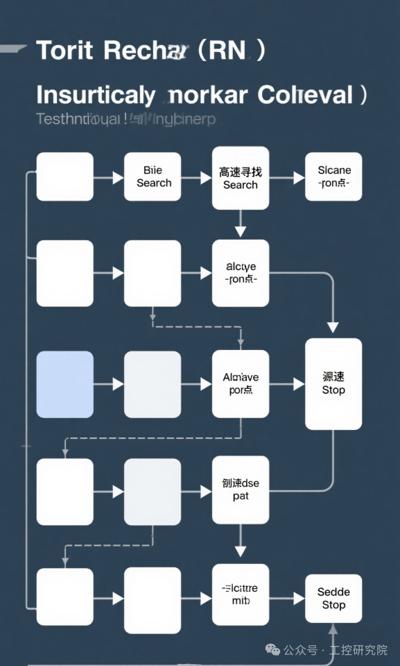
Workflow:
- Start searching for the origin at the high speed set by S1.
- After detecting the origin signal (DOG signal), decelerate.
- Continue moving at the creep speed set by S2.
- Stop after detecting the zero signal.
- Clear the current position register.
Application Scenarios: All systems requiring precise positioning need to execute homing at startup to establish a position reference.
3. Parameter Settings
Positioning control requires the configuration of the following key parameters (via special data registers D):
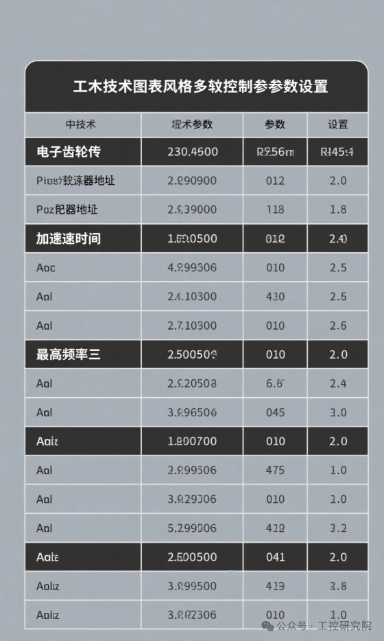
3.1 Speed Parameters
- Maximum Output Frequency: D8145 (Y0), D8146 (Y1).
- Homing Speed: D8340 (Y0), D8350 (Y1).
- Creep Speed: D8341 (Y0), D8351 (Y1).
3.2 Acceleration and Deceleration Parameters
- Acceleration Time: D8348 (Y0), D8358 (Y1).
- Deceleration Time: D8349 (Y0), D8359 (Y1).
3.3 Electronic Gear Ratio
The electronic gear ratio is used to match the pulse count with the actual mechanical displacement, calculated using the following formula:
plaintext
Electronic Gear Ratio = (Pulses per Revolution of Motor × Mechanical Reduction Ratio) / (Ball Screw Pitch × Subdivision Factor)
4. Application Cases
4.1 Single Axis Positioning Control
Below is a simple example of a single-axis positioning control program:
plaintext
// Initialize parameters<span>MOV K5000 D8145 // Set Y0 maximum frequency to 5000Hz</span><span>MOV K100 D8348 // Set acceleration time to 100ms</span><span>MOV K100 D8349 // Set deceleration time to 100ms</span><span>// Homing</span><span>LD M0 // M0 is the homing start signal</span><span>ZRN K2000 K500 Y0 // Return at 2000Hz speed, creep speed 500Hz</span><span>// Relative Positioning</span><span>LD M1 // M1 is the relative positioning start signal</span><span>DRVI K10000 K3000 Y0 Y4 // Move relative 10000 pulses, speed 3000Hz</span><span>// Absolute Positioning</span><span>LD M2 // M2 is the absolute positioning start signal</span><span>DRVA K50000 K3000 Y0 Y4 // Move to absolute position 50000 pulses, speed 3000Hz</span>
4.2 Multi-Axis Coordinated Control
In multi-axis control, independent parameter registers need to be allocated for each axis to avoid parameter conflicts:
plaintext
// X-axis parameters<span>MOV K5000 D8145 // Y0 maximum frequency 5000Hz</span><span>MOV K100 D8348 // Y0 acceleration time 100ms</span><span>MOV K100 D8349 // Y0 deceleration time 100ms</span><span>// Y-axis parameters</span><span>MOV K5000 D8146 // Y1 maximum frequency 5000Hz</span><span>MOV K100 D8358 // Y1 acceleration time 100ms</span><span>MOV K100 D8359 // Y1 deceleration time 100ms</span><span>// Multi-axis synchronous motion</span><span>LD M3 // M3 is the start signal</span><span>DRVA K30000 K4000 Y0 Y4 // X-axis moves to 30000 pulses</span><span>DRVA K20000 K4000 Y1 Y5 // Y-axis moves to 20000 pulses</span>
5. Precautions
-
Hardware Configuration:
- Must use transistor output type PLC.
- The pulse output line should use twisted shielded wire.
- Servo/stepper drivers must be properly grounded.
Software Settings:
- The pulse output port must be configured for high-speed output mode.
- Acceleration and deceleration times should be adjusted according to the characteristics of the mechanical system.
- The electronic gear ratio setting must be accurate; otherwise, it will affect positioning accuracy.
Safety Protection:
- Soft limits and hard limits must be set for protection.
- There should be alarm handling for homing failures.
- The emergency stop signal should be directly connected to the driver.
Tuning Tips:
- First, perform point-to-point debugging to confirm direction and speed.
- Gradually increase the movement distance and observe positioning accuracy.
- Use the PLC monitoring function to observe the actual output pulse count.
6. Conclusion
The positioning instructions of Mitsubishi PLCs provide powerful and flexible motion control capabilities. By appropriately selecting instructions such as DRVI, DRVA, PLSV, and ZRN, various positioning needs of automated equipment can be met. In practical applications, it is essential to choose the right instructions based on specific control requirements and correctly configure related parameters. Additionally, attention should be paid to the matching of mechanical systems and electrical control systems to achieve optimal control effects and positioning accuracy.
With the development of industrial automation, the positioning functions of Mitsubishi PLCs are continuously enhanced, supporting more complex multi-axis synchronization, cam control, and other advanced functions. Mastering these basic positioning instructions is the foundation for further learning advanced motion control.
 Like, Follow + Share!