By utilizing wireless connectivity, designers can transform non-smart products into smart integrated devices for the Internet of Things (IoT), enabling data transmission to the cloud for artificial intelligence (AI)-based analysis, while allowing devices to receive over-the-air (OTA) commands, firmware updates, and security enhancements.
However, adding a wireless link to a product is not a simple task. Before the design phase begins, designers must select a wireless protocol, which can be a tricky task. For example, some wireless standards operate in the popular unlicensed 2.4 GHz spectrum. All these standards represent trade-offs in terms of transmission range, throughput, and power consumption. To choose the most suitable protocol for a specific application, the application requirements must be carefully evaluated against the characteristics of the protocol.Thus, even with highly integrated new transceivers, designing radio frequency (RF) circuits remains a challenge for many design teams, leading to cost overruns and schedule delays. Additionally, RF products will require operational certification, which can be a complex and time-consuming process in itself.A solution is to design based on certified modules that use multi-protocol system-on-chip (SoC). This eliminates the complexity of RF design with discrete components and allows for flexible wireless protocol selection. This modular approach provides designers with an on-demand wireless solution, making it easier to integrate wireless connectivity into products and achieve certification.This article outlines the benefits of wireless connectivity, explores the advantages of several major 2.4 GHz wireless protocols, briefly analyzes hardware design issues, and introduces a suitable RF module from Würth Elektronik that meets global regulatory certification requirements. The article also discusses the certification process required to meet global regulations, explores application software development, and introduces a software development kit (SDK) to help designers get started with the module.
01
Advantages of Multi-Protocol Transceivers
No single short-range wireless technology dominates, as each technology makes trade-offs to meet the needs of its target applications. For example, to provide longer transmission distances and/or higher throughput, power consumption must be increased. Other important factors to consider include interference resistance, mesh networking capabilities, and Internet Protocol (IP) interoperability.
Among various mature short-range wireless technologies, three are clearly leading: Low Energy Bluetooth (Bluetooth LE), Zigbee, and Thread. Since these three protocols inherit the genes of the IEEE 802.15.4 specification, they share some similarities. This specification describes the physical layer (PHY) and media access control layer (MAC) for low data rate wireless personal area networks (WPANs). Although Zigbee has some sub-GHz variants, these technologies typically operate in the 2.4 GHz band.
Low Energy Bluetooth is suitable for IoT applications, such as smart home sensors that only need to transmit data occasionally and have lower speed requirements (Figure 1). The interoperability of Low Energy Bluetooth with the Bluetooth chips used in most smartphones is a significant advantage for consumer-facing applications like wearables. The main drawback of this technology is the need for expensive and power-hungry gateways to connect to the cloud, along with poor mesh networking capabilities.

Figure 1: Low Energy Bluetooth is ideal for smart home sensors, such as cameras and thermostats. Its interoperability with smartphones simplifies the configuration of compatible products. (Image source: Nordic Semiconductor)
Zigbee is also an ideal choice for low-power and low-throughput applications, including industrial automation, commercial, and home environments. Its throughput is lower than that of Low Energy Bluetooth, but its transmission range and power consumption are similar. Zigbee cannot interoperate with smartphones and does not provide native IP functionality. A key advantage of Zigbee is that it was designed for mesh networking from the outset.Like Zigbee, Thread operates using the IEEE 802.15.4 PHY and MAC, supporting large mesh networks of up to 250 devices. The difference between Thread and Zigbee is that it uses 6LoWPAN (a combination of IPv6 and low-power WPAN), which simplifies connectivity with other devices and the cloud, although it requires a network edge device called a border router for connection. (See “Important Considerations for Short-Range Wireless Technologies.”)While standard-based protocols dominate, proprietary protocols in the 2.4 GHz band still have a place. Although these protocols limit connectivity with other devices equipped with the same manufacturer’s chips, they can be fine-tuned to optimize power consumption, transmission range, interference resistance, or other important operating parameters. The IEEE 802.15.4 PHY and MAC fully support 2.4 GHz proprietary wireless technologies.Due to the widespread adoption of these three short-range protocols and the flexibility offered by 2.4 GHz proprietary technologies, it can be challenging to choose a suitable protocol for the broadest applications. In the past, designers had to select a wireless technology and then redesign the product when variants using different protocols were needed. However, since these protocols all use PHY based on similar architectures and operate in the 2.4 GHz band, many chip suppliers offer multi-protocol transceivers.These chips allow for a single hardware design that can be reconfigured for several protocols simply by uploading new software. Moreover, the product can be equipped with multiple software stacks, with switching between stacks monitored by a microcontroller unit (MCU). For example, a user can configure a smart home thermostat using Low Energy Bluetooth via a smartphone and then switch the device’s protocol to join a Thread network.Nordic Semiconductor’s nRF52840 SoC supports Low Energy Bluetooth, Bluetooth mesh, Thread, Zigbee, IEEE 802.15.4, ANT+, and 2.4 GHz proprietary stacks. The Nordic SoC also integrates an Arm®Cortex®-M4 MCU to run RF protocols and application software, providing 1 MB of flash and 256 KB of RAM. When operating in Low Energy Bluetooth mode, the SoC offers a maximum raw data throughput of 2 Mbit/s. The SoC operates on a 3 VDC input power supply, with a transmit current of 5.3 mA at 0 dB (decibel reference of 1 mW) output power, and a receive (RX) current of 6.4 mA at a raw data rate of 1 Mbit/s. The maximum transmit power of the nRF52840 is +8 dBm, with a sensitivity of -96 dBm (Low Energy Bluetooth, 1 Mbit/s).
02
The Importance of Good RF Design
Although wireless SoCs like Nordic’s nRF52840 are powerful devices, good design practices are still required to maximize their RF performance. In particular, engineers must consider various factors such as power filtering, external crystal timing circuits, antenna design and placement, and critically, impedance matching.The key parameter that distinguishes good and poor RF circuits is impedance (Z). At high frequencies, such as the 2.4 GHz frequency used in short-range wireless, the impedance at a point on the RF trace is related to the characteristic impedance of the trace, which in turn depends on the printed circuit board substrate, trace dimensions, distance to the load, and the load’s impedance.In practice, when the load impedance (the antenna in the transmit system, and the transceiver SoC in the receive system) equals the characteristic impedance, the impedance measured at any distance from the load on the trace is the same. This minimizes line losses and achieves maximum power transfer from the transmitter to the antenna, thereby improving stability and extending the transmission range. Therefore, good design practices involve constructing matching networks to ensure that the impedance of RF devices equals the characteristic impedance of the printed circuit board traces. (See “Bluetooth 4.1, 4.2, and 5 Low Energy Bluetooth SoCs and Tools Address IoT Challenges (Part 2).”)
Matching networks consist of one or more shunt inductors and series capacitors. The challenge for designers is how to select the best network topology and component values. Manufacturers often provide simulation software to assist in matching circuit design, but even when following good design rules, the RF performance of the designed circuit can often be disappointing, lacking sufficient transmission range and reliability. This leads to the need for more design iterations to modify the matching network (Figure 2).
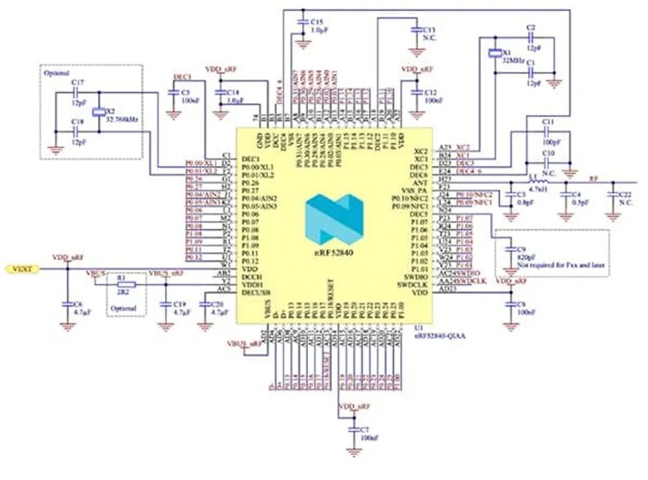 Figure 2: Nordic’s nRF52840 requires external circuitry to function. The external circuitry includes input voltage filtering, support for external crystal timing, and connections to the SoC’s antenna (ANT) pin, with an impedance matching circuit between the SoC and the antenna. (Image source: Nordic Semiconductor)
03
Advantages of Modules
Designing short-range wireless circuits with discrete components has some advantages, particularly lower bill of materials (BoM) costs and space savings. However, even if designers follow one of the many excellent reference designs provided by SoC suppliers, other factors can significantly impact RF performance, including component quality and tolerances, circuit board layout, substrate characteristics, and end device packaging.Another approach is to use third-party modules for wireless connectivity. These modules are fully assembled and optimized solutions that enable “on-demand” wireless connectivity. In most cases, the modules have already been certified for use in global markets, saving designers time and money required for RF regulatory certification.Using modules also has some drawbacks. These drawbacks include higher costs (depending on size), larger final product dimensions, greater reliance on a single supplier and their production capabilities, and sometimes a reduction in the number of available pins on the SoC that the module is based on. However, if design simplicity and faster time-to-market outweigh these drawbacks, then using a module is the best choice.An example based on Nordic’s nRF52840 is Würth Elektronik’s Setebos-I 2.4 GHz radio module 2611011024020. This compact module measures 12 × 8 × 2 mm, has a built-in antenna, features a cover to minimize electromagnetic interference (EMI), and comes with firmware supporting Bluetooth 5.1 and proprietary 2.4 GHz protocols (Figure 3). As mentioned, with the appropriate firmware, the core SoC of this module can also support Thread and Zigbee.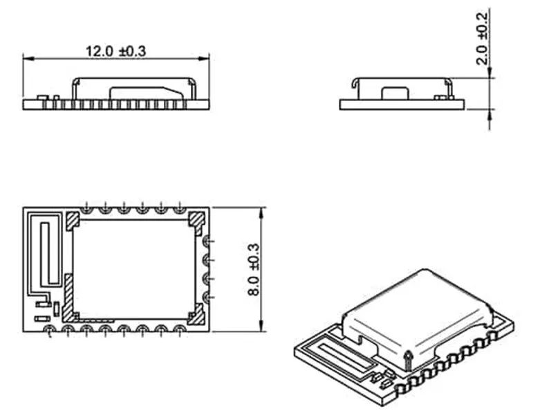 Figure 3: The Setebos-I 2.4 GHz radio module is compact, with a built-in antenna and a cover to limit electromagnetic interference. (Image source: Würth Elektronik)The module accepts an input of 1.8-3.6 V, with a current of only 0.4 µA in sleep mode. Its operating frequency covers the industrial, scientific, and medical (ISM) band, centered at 2.44 GHz (2.402 to 2.480 GHz). Under ideal conditions, the line-of-sight propagation distance between the transmitter and receiver can reach 600 meters at 0 dBm output power, with a maximum Low Energy Bluetooth throughput of 2 Mbit/s. The module has a built-in quarter-wave (3.13 cm) antenna but can also extend its transmission range by connecting an external antenna to the ANT terminal on the module (Figure 4).
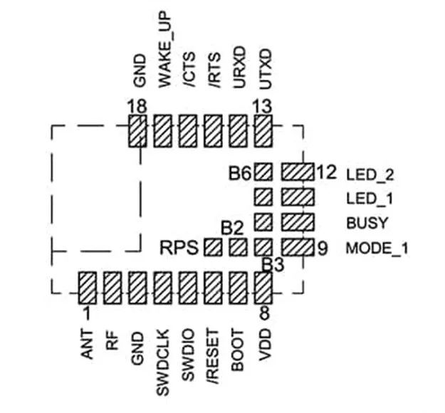 Figure 4: The Setebos-I 2.4 GHz radio module includes a pin for an external antenna (ANT) to extend the radio’s transmission range. (Image source: Würth Elektronik)The Setebos-I radio module connects to the pins of the nRF52840 SoC via pads. Table 1 lists the functions of each module pin. Pins “B2” to “B6” are programmable GPIOs that can be used to connect sensors such as temperature, humidity, and air quality devices.
|
Table 1: Shows the pin names of the Setebos-I 2.4 GHz radio module. The LED outputs can be used to indicate radio transmission and reception. (Image source: Würth Elektronik)
04
Certification of Short-Range Wireless ProductsAlthough the 2.4 GHz band is an unlicensed spectrum allocation, radio devices operating in this band must still comply with local regulations, such as those from the Federal Communications Commission (FCC) in the United States, the European Conformity (CE) declaration, or the Telecommunications Engineering Center (TELEC) in Japan. To comply with these regulations, products must be submitted for testing and certification, a process that can be very time-consuming and costly. If the RF product fails any part of the testing, it must be resubmitted. If the module is to be used in Bluetooth mode, it must also be listed with the Bluetooth Special Interest Group (SIG).Certification of the module does not automatically grant certification to the final product using the module. However, if the final product does not use other wireless devices like Wi-Fi, this typically turns the certification of the final product into a paperwork exercise without the need for extensive retesting. The same is often true when being listed with Bluetooth. Once certified, products using the module will be labeled with FCC, CE, and other relevant ID numbers (Figure 5).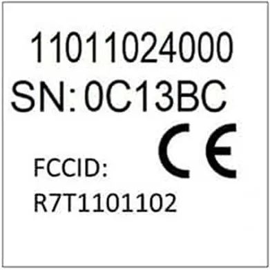 Figure 5: Example of an ID label on the Setebos-I module, indicating that it has passed CE and FCC RF certification. Certification can often be inherited by the final product with some simple paperwork, without the need for retesting. (Image source: Würth Elektronik)Module manufacturers typically obtain RF certification for their modules in the regions where they intend to sell their products (and list with Bluetooth if appropriate). Würth Elektronik has completed this work for the Setebos-I radio module, but it must be used with the factory firmware. In terms of Bluetooth operation, the module has been pre-certified, provided it is used with Nordic’s S140 Low Energy Bluetooth factory stack or the stack provided through the company’s nRF Connect SDK software development kit.Würth and Nordic’s firmware is stable and reliable for any application. However, if designers decide to use an open standard Low Energy Bluetooth or 2.4 GHz proprietary stack, or a stack from other commercial vendors, and reprogram the module, they will need to restart the certification process from scratch in the intended operating area.
05
Development Tools for the Setebos-I Radio Module
For advanced developers, Nordic’s nRF Connect SDK provides comprehensive design tools for developing application software for the nRF52840 SoC. The nRF Connect for VS Code extension is our recommended integrated development environment (IDE) for running the nRF Connect SDK. The nRF Connect SDK can also be used to upload alternative Low Energy Bluetooth or 2.4 GHz proprietary protocols to the nRF52840. (Refer to the earlier comments regarding the impact on module certification.)
The nRF Connect SDK works with the nRF52840 DK development kit (Figure 6). This hardware features the nRF52840 SoC and supports prototype code development and testing. Once the application software is ready, the nRF52840 DK can be used as a J-LINK programmer to transfer code to the flash memory of the Setebos-I radio module’s nRF52840 via the module’s “SWDCLK” and “SWDIO” pins.
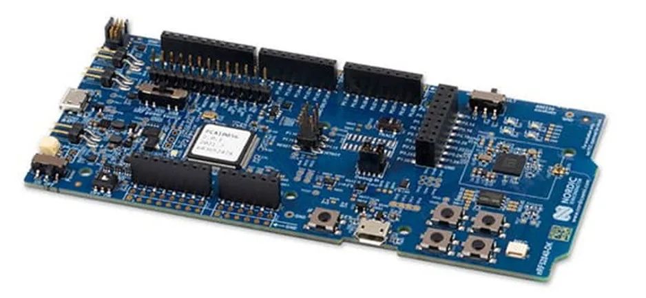 Figure 6: Nordic’s nRF52840 DK can be used to develop and test application software. The development kit can then be used to program other nRF52840 SoCs, such as the SoC used on the Setebos-I module. (Image source: Nordic Semiconductor)Applications developed using Nordic’s development tools are designed to run on the embedded Arm Cortex-M4 MCU of the nRF52840. However, there may be cases where the final product is equipped with another MCU, and developers wish to use it to run application code and monitor the wireless connection. Alternatively, developers may be more familiar with the development tools of other popular host microprocessors, such as STMicroelectronics ’s STM32F429ZIY6TR, which is also based on the Arm Cortex-M4 core.To enable an external host microprocessor to run application software and monitor the nRF52840 SoC, Würth Elektronik provides the Wireless Connectivity SDK, which is a set of software tools that facilitate rapid software integration of the company’s wireless modules with many popular processors, including the STM32F429ZIY6TR chip. The SDK includes C language drivers and examples that communicate with connected radio devices using UART, SPI, or USB peripherals of the underlying platform (Figure 7). Developers only need to port the SDK C code to the host processor. This significantly reduces the time required to design the software interface for the radio module.
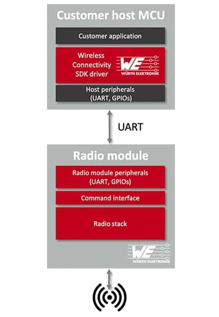 Figure 7: The Wireless Connectivity SDK drivers enable developers to easily drive the Setebos-I radio module using an external host microprocessor via the UART port. (Image source: Würth Elektronik)The Setebos-I radio module uses a “command interface” for configuration and executing operational tasks. This interface provides up to 30 commands to perform various tasks, such as updating various device settings, transmitting and receiving data, and putting the module into various low-power modes. The connected radio device must operate in command mode to use the Wireless Connectivity SDK.
Conclusion
Selecting a single wireless protocol for interconnected products is challenging, and designing radio circuits from scratch is even more daunting. Wireless modules like Würth Elektronik’s Setebos-I not only offer flexibility in protocol selection but also provide an on-demand connectivity solution that complies with regulatory requirements in different operating regions. The Setebos-I module comes with Würth’s Wireless Connectivity SDK, allowing developers to easily and quickly control the module using their chosen host MCU.
Editor’s Note
As mentioned in the article, a key condition for product intelligence is the ability to connect wirelessly, which is also the foundation for achieving the Internet of Things. Whether selecting a suitable wireless protocol, designing wireless RF circuits, or undergoing related certification, these are all challenging tasks for design engineers. The methods and tools mentioned in the article can help colleagues shorten product design cycles and accurately deliver smart products. Are you currently designing the wireless unit of a product? What pain points, experiences, and insights do you have during the design process?Feel free to leave a comment and share your thoughts!
Like Digi-Key’s articles?
Visit Digi-Key’s official website now,
or follow Digi-Key’s official WeChat digikey_electronics!