Click on the “Little P Classmate” above to follow and learn more exciting content!
The S32G, as NXP’s next-generation high-performance automotive-grade gateway chip, supports functional safety levels up to ASIL D. It uses four Arm® Cortex®-A53 cores and three dual-core lockstep Arm Cortex-M7 cores, providing not only excellent safety computing performance but also a combination of automotive and enterprise networking technologies, as well as various interfaces suitable for automotive networks (CAN/LIN/FlexRay/Ethernet, etc.).
BSP 28.0 was officially launched in early May, and individual users can download it from NXP’s official website.
By reading this article, you can gain the following knowledge points:
-
How to create a new layer in Yocto
-
How to add your own drivers and apps in Yocto
-
Understanding the Linux character device driver framework
Software environment: BSP 28.0
Hardware platform: S32G-VNP-RDB2.
1 Create a New Layer
1.1 Why Create a New Layer
The release of BSP is based on NXP’s hardware platforms, such as RDB/EVB (Reference Design Board / Evaluation Board). In reality, the user’s hardware circuit will certainly differ from NXP’s; moreover, there may be certain software functionalities that are not fully developed, failing to meet customer needs. Therefore, users need to modify the BSP released by NXP to adapt (port) it to their own hardware boards. This adaptation can be achieved by directly modifying NXP’s BSP, which is a simple and straightforward method but has a major drawback: once NXP’s BSP has a new update, maintaining one’s own code becomes difficult. Another method is to create your own Yocto layer, implementing kernel modifications (patching) or adding drivers in your own layer. Without modifying the existing layer contents, drivers, or configurations in Yocto, even if the BSP changes, it will hardly affect your development.
1.2 How to Create a New Layer
Step 1. First, compile a BSP image that has not been modified (refer to the document Linux BSP 28.0 User Manual for S32G274A, Chapter 2.1 Building the Linux BSP using Yocto, compile fsl-image-auto).
Step 2. Create a Meta layer
Create a folder cs-gw-s32grdb2 under the downloads directory and create the layer.
$ cd ~/bsp28.0/fsl-auto-yocto-bsp/downloads/
$ mkdir cs-gw-s32grdb2
$ cd cs-gw-s32grdb2
$ bitbake-layers create-layer ./meta-cs-learning_28

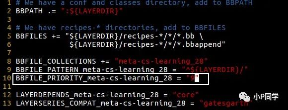
A new meta layer has been generated and provides an example recipe.
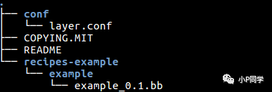
Tips: The priority of the new layer is 6, but the priority of meta-alb is 8. To ensure that the recipes-* (recipes) under our newly created meta layer are executed by OE first, you can modify the BBFILE_PRIORITY variable to 9.
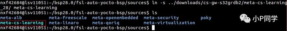
Step 3. Create a soft link for the new meta layer to the source directory
$ cd ../source
$ ln -s ../downloads/cs-gw-s32grdb2/meta-cs-learning_28/ meta-cs-learning
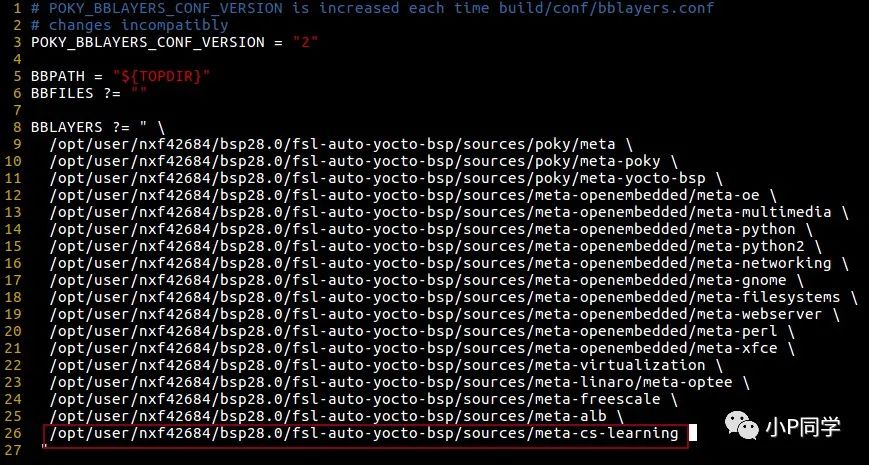
Step 4. Add the newly created layer to the Yocto project’s environment variables (build_s32g274ardb2/conf/bblayers.conf).
$ cd build_s32g274rdb2
$ vim conf/bblayers.conf
Add the absolute path of meta-cs-learning to the BBLAYERS variable.
Above is the introduction to creating a layer in Yocto.
2 Linux Character Device Driver Development – LED
Implement a simple LED driver using the Linux character device driver framework.
2.1 Add RGB Device Driver Recipe
Step 1. Create a recipe for the LED driver
$ cd meta-cs-learning
/* Create the directory structure for the LED driver */
$ mkdir -p recipes-kernel/s32grdb2-rgb/s32grdb2-rgb/source
Step 2. Create a bb file in the recipes-kernel/s32grdb2-rgb directory
$ touch s32grdb2-rgb_0.1.bb
Tips: The naming rule for recipe files is ${PN}_${PV}.bb
-
PN: Represents the package file name extracted from the recipe file (e.g., s32grdb2-rgb)
-
PV: Represents the version number (e.g., 0.1)
Step 3. Write the bb file. You can find a similar one to modify or write from scratch. Below is a template I provide, and readers can adapt it by replacing the highlighted parts of the code for different drivers.
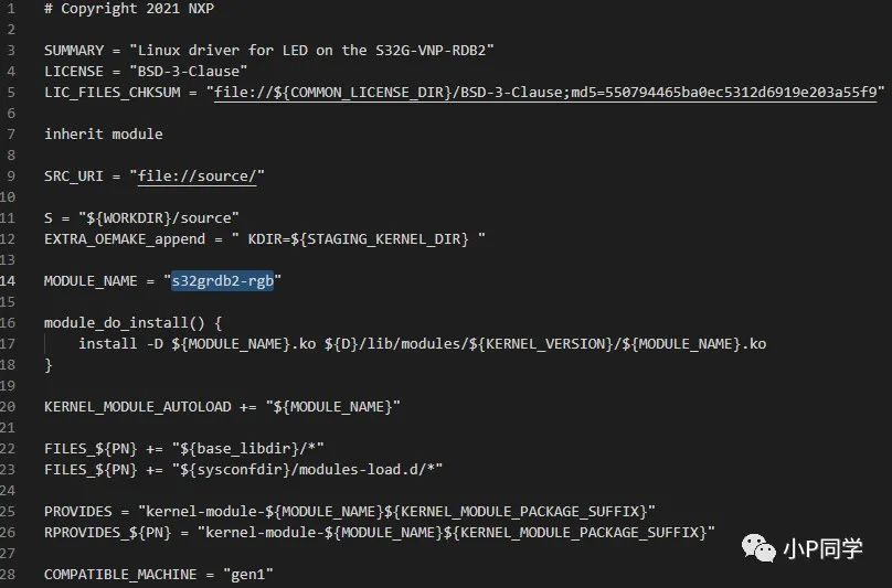
Line 5, LIC_FILES_CHKSUM is mandatory. You can also use other files you specify, such as the driver code file or Makefile. If the specified file is modified, the md5 value needs to be modified accordingly. It is recommended to directly use the LICENSE text.
Line 16, configures the rootfs path for storing the ko file.
Line 20 indicates that the driver module will be automatically loaded after startup.
Tips: It is recommended not to spend too much effort researching the meanings of other parameters. Those interested can refer to the following link: https://www.yoctoproject.org/docs/2.1/ref-manual/ref-manual.html.
Step 4. Write the driver and Makefile in the source directory. The following is the directory structure of the RGB driver
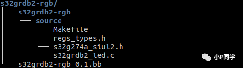
Step 5. Write the Makefile
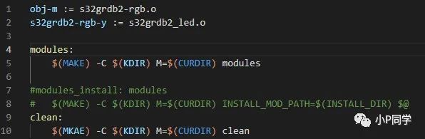
Lines 1 and 2 indicate that the s32grdb2_led.c file is compiled into the s32grdb2-rgb.ko module. Additionally, note that the name of the obj-m variable must match the name in the bb file.
2.2 RGB Driver Introduction
2.2.1 Hardware Principle Analysis
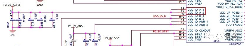
On the S32G-VNP-RDB2, there is an RGB device controlled by three GPIOs (which are actually three LEDs displaying different colors). The hardware circuit diagram is as follows:
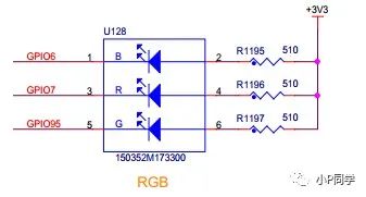
Control Principle:
Since these three GPIOs can output a 3.3V high level, when GPIOx outputs high (1), the LED is off, and when GPIOx outputs low (0), the LED is on.

Tips: These three GPIOs correspond to the same power domain VDD_IO_A; the circuit diagram also shows that VDD_IO_A is connected to the P3_3V_IO3P3 power rail.
2.2.2 S32G SIUL2 Introduction
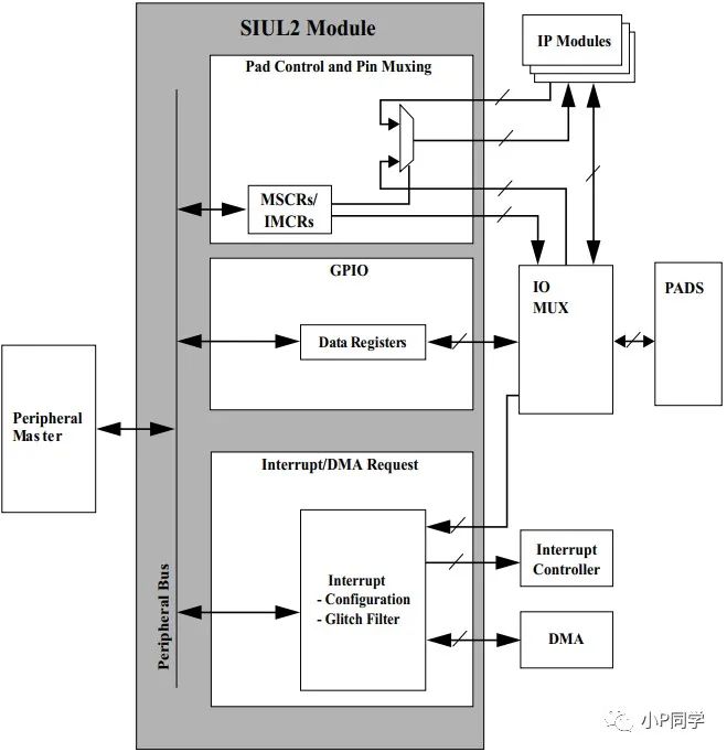
From the structure diagram of the SIUL2 module below, it can be seen that the PADS (pins) are configured through the MSCR and IMCR registers. The MSCR/IMCR registers can configure the PADS as GPIO or certain IP (such as CAN, LIN, GMAC, SPI…) function pins through IO multiplexing. When configured as GPIO mode, the pad can be read and written through GPDIx / GPDOx registers.
The MSCR register is responsible not only for configuring IO multiplexing but also for configuring electrical characteristics.
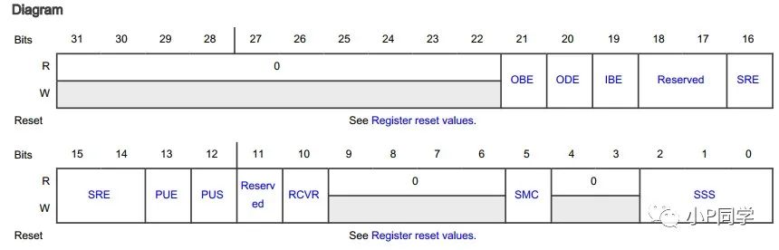
OBE(bit21): Output enable bit.
ODE(bit2): Open-drain output enable bit. The open-drain output mode cannot output a high level, so a pull-up resistor must be connected to the pin. It is generally used in scenarios for level conversion, for example, when the GPIO connecting to the LED can only output 1.8V, it cannot control the LED when the positive terminal is connected to a 3.3V power supply. In this scenario, the GPIO can be configured in open-drain mode with an external pull-up resistor connected to 3.3V to control the LED switch. Additionally, pins with open-drain outputs are connected together to form a “wired-AND” relationship; if one pin is pulled low, all connected pins will be pulled low. The I2C bus is based on this principle to determine the bus state.
IBE(bit19): Input enable bit.
SRE(bit16-14): Rate control bits. The higher the rate configuration, the faster the IO level response.
PUE(bit13): Enable pull-up/down.
PUS(bit12): Pull-up or pull-down selection bit.
RCVR(bit10): Related to the value captured by input; currently, it is unknown in which application scenario it will be used.
SMC(bit5): Enable safety mode.
SSS(bit2-0): Multiplexing configuration, configuring the function of the IO.
2.2.3 Bare Metal Code Driver Implementation
Pseudocode
int main(){/*OBE = 1, ODE = 1, IBE = 0, PUS = 0 pull down PUE = 1 PULL enable SSS = 0x0*/ SIUL2_0.MSCR[x].R = 0x303000; /*Configure GPIO output to high or low, achieve LED switch control*/SIUL2_0.GPDOx.R = LEDOFF or LEDON;return 0;}2.2.4 Linux Driver Code Implementation
Writing drivers under Linux must comply with the Linux driver framework, but ultimately, the corresponding hardware registers must be configured.
2.2.4.1 Address Mapping
To run an older version of Linux on the processor, the processor must support MMU (now the Linux kernel can support processors without MMU). The main function of the MMU is to complete the mapping of virtual addresses to physical addresses and to protect memory (such as Data Access Permissions to control read and write permissions).
The S32G is based on the ARMv8 architecture, and its address mapping relationship is shown in the figure below:
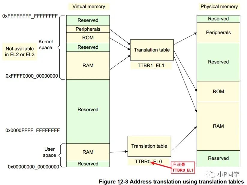
The base address of the page table in Kernel Space is stored in the TTBR1_EL1 register, and the base address of the User Space page table is stored in the TTBR0_EL1 register, where the high bits of the kernel address space are all 1 (0xFFFF0000_00000000 ~ 0xFFFFFFFF_FFFFFFFF), and the high bits of the user address space are all 0 (0x00000000_00000000 ~ 0x0000FFFF_FFFFFFFF). This is a significant difference from ARM32. Currently, the maximum width of the virtual address supported by AArch64 is 48 bits, and the size of the virtual address space can be configured using the TCR_ELx register. The default for the S32G BSP is 48 bits. (MMU is a bit complex; if you delve too deeply into the details, you might get stuck. Just a brief mention!)

After enabling the MMU, you can no longer directly configure the SIUL2_0 register addresses as in bare-metal code. You need to obtain the virtual address corresponding to the base address of SIUL2_0 in Linux before you can configure data into the target register. Linux has provided two functions for converting between virtual and physical addresses: ioremap() and iounmap().
2.2.4.2 Linux Driver Code Implementation for LED Control
Pseudocode:
#define SIUL2_0 (*p_siul2_0) { struct SIUL2_0_tag *p_siul2_0 = ioremap_nocache(SIUL2_0_REG_BASE, SIUL2_0_REG_SIZE); SIUL2_0.GPDO6.R = LEDOFF or LEDON; SIUL2_0.GPDO7.R = LEDOFF or LEDON; SIUL2_0.GPDO95.R = LEDOFF or LEDON; iounmap(p_siul2_0); return 0;}2.2.4.3 Linux Character Device Driver Model
The following part of the LED driver code can be found on GitHub: https://github.com/harry-Zhao/cs-gw-s32grdb2.git
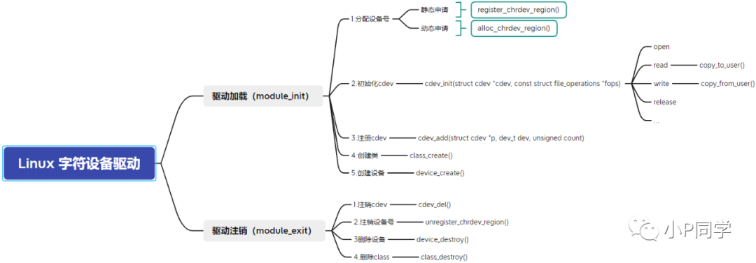
static int __init led_init(void){ int ret = 0; uint8_t led_num = 0; printk("%s\n", __FUNCTION__); led_pad_init(); RGB_init(); /** * 1. Create the number of the device */ chrled.major = 0; // Select dynamic allocation of device number if(chrled.major) { chrled.devid = MKDEV(chrled.major, 0); register_chrdev_region(chrled.devid, LED_CNT, LED_NAME); } else { alloc_chrdev_region(&chrled.devid, 0, LED_CNT, LED_NAME); // Dynamically allocate device number, starting from 0, allocating 3 chrled.major = MAJOR(chrled.devid); // @chrled.devid: output parameter for first assigned number } // printk("chrled major = %d\n", chrled.major); /* *2. initialize cdev Associate the character device (cdev) with file operation functions (file_operation) */ chrled.cdev.owner = THIS_MODULE; cdev_init(&chrled.cdev, &chrled_fops); /* *3. add cdev Register the character device to the kernel */ cdev_add(&chrled.cdev, chrled.devid, LED_CNT); /* *4. create class Create a class for this device * Use udev to implement automatic creation of device files, create a class (create a directory under /sys/class/, the directory name is the second parameter) * After the class is created successfully, use device_create() to create a device node in the /dev directory */ chrled.class = class_create(chrled.cdev.owner, LED_NAME); if(IS_ERR(chrled.class)) { return PTR_ERR(chrled.class); } /* *5. create device Create 3 LED devices * Sub-device number 0: led-Blue * Sub-device number 1: led-Red * Sub-device number 2: led-Green */ for(led_num=0; led_num<led_cnt; led_num++) {< div=""> chrled.device = device_create(chrled.class, NULL, MKDEV(chrled.major, led_num), NULL, rgb_name[led_num]); if(IS_ERR(chrled.device)) { return PTR_ERR(chrled.device); } } return 0;}static void __exit led_exit(void){ uint8_t led_num = 0; printk("%s\n", __FUNCTION__); cdev_del(&chrled.cdev); unregister_chrdev_region(chrled.devid, LED_CNT); for(led_num=0; led_num<led_cnt; led_num++) {< div=""> device_destroy(chrled.class, MKDEV(chrled.major, led_num)); } class_destroy(chrled.class);}module_init(led_init);module_exit(led_exit);3. Writing an APP to Test the Driver
3.1 Add LED Test APP Recipe
Create a new recipes-app directory under the meta-cs-learning layer to add user-level apps. Create ledAPP, the directory structure is as follows.
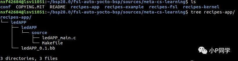
The Makefile and bb file are not much different from the driver layer, so they will not be elaborated on.
3.2 Write Test Code
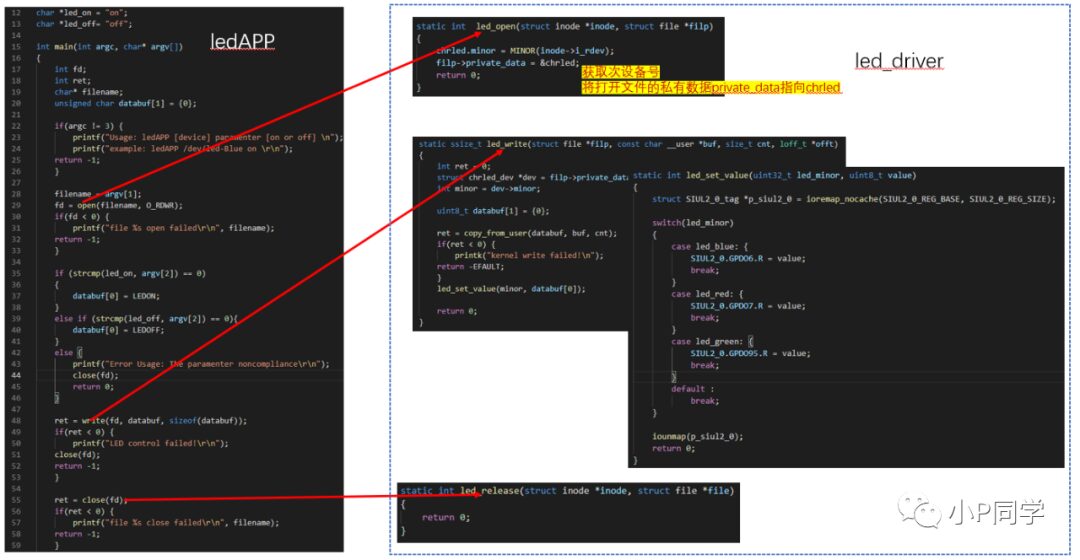
Lines 29, 48, and 55 will call system calls from user space to kernel space and then call functions from the LED driver layer to control the LEDs. Their association is achieved through the cdev_init() function.
Tips: The led_open() function extracts the sub-device number from the opened device identifier using MINOR(inode->i_rdev), allowing the driver to know which LED in the RGB device is being operated on.
3.3 Testing
Method 1: Copy the compiled driver module and APP to the Linux file system, then load the driver module and test it.
Method 2: Based on Yocto, compile and package the driver module and APP directly into the BSP image.
Advantages and disadvantages: Method 1 is more useful during the development phase because the speed of compiling and copying a single file is much higher than that of Method 2. Method 2 is suitable for final release.
Here, we mainly introduce the implementation of Method 2:
Step 1. Create a new recipes-fsl directory under the meta-cs-learning layer to add image files. The directory structure is as follows:
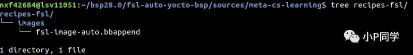
Tips: I compiled the object fsl-image-auto, so Yocto will append the contents of fsl-image-auto.bbappend to the meta-alb/recipes-fsl/images/fsl-image-auto.bb file during compilation.
Step 2. Write the content of fsl-image-auto.bbappend as follows:
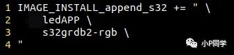
Step 3. After compiling, write the fsl-image-auto-s32g274ardb2.sdcard file to the SD card or eMMC and start testing
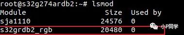
I. Use the lsmod command to check whether the driver module has been automatically loaded
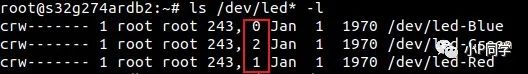
II. Check whether the sub-device numbers of the three devices created by the driver correspond in the /dev directory
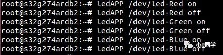
III. Test whether the LED switch function works normally
Disclaimer: All articles from this public account are free to read, and all views/descriptions in the text are personal actions and do not represent any company’s official views. All demos/code/programs are for reference and learning only, and do not guarantee quality. If used for commercial purposes, the responsibility lies with the user.