Cao HX, Nguyen VD, Park JO, Choi E, Kang B. Acoustic Actuators for the Manipulation of Micro/Nanorobots: State-of-the-Art and Future Outlooks. Micromachines (Basel). 2024 Jan 26;15(2):186. doi: 10.3390/mi15020186. PMID: 38398914; PMCID: PMC10890471.
Compared to other actuation methods, acoustic actuators have the unique capability of non-contact operation of small objects (such as micro and nanoscale robots). Additionally, they possess the ability to penetrate skin, capturing and manipulating micro/nanorobots carrying therapeutic agents in various media. In this review, we summarize the advancements in the manipulation of micro/nanorobots used in various biomedical applications through acoustic actuators. First, we introduce actuation methods that use sound waves to manipulate objects, including the working principles and different types of acoustic actuators commonly employed. We then review applications involving the manipulation of different types of devices, including bubble-based microbots, non-bubble robots, biohybrid microbots, and nanorobots. Finally, we discuss the challenges and future prospects of developments in this field.

The term “robot” originates from the Czech word “robota,” meaning “forced labor.” It was first introduced in the 1921 play R.U.R. (translated as “Rossum’s Universal Robots”). Subsequently, Isaac Asimov (a Russian-American science fiction writer) depicted robots as empathetic entities that meet human needs, viewing them as a more advanced and refined species. Asimov proposed the “Three Laws of Robotics,” which govern his own robot creations and influence the portrayal of robots in various other science fiction narratives. Thus, despite the existence of multiple definitions, the question of how to define robots in real life remains challenging. In this review, we follow the definition proposed by the American Robotics Institute in 1979: a reprogrammable multifunctional mechanical device designed to move materials, parts, tools, or specialized devices to perform various tasks through various programmed motions. In the context of this review, the term micro/nanorobots (MNR) refers to wireless robots ranging from nano to submillimeter scales. These robots are designed to autonomously perform specific tasks at the microscopic scale or can be controlled externally. Compared to traditional robots, MNRs can access very small areas that were previously unobserved, such as microchannels [1,2,3,4,5] and microcontainers [6]. MNRs show great potential in various biomedical applications, including chemical detection [7,8], biosensing [9,10,11,12], and microsurgery. In recent decades, the rapid development of MNR manufacturing technologies has greatly propelled the advancement of autonomous robotic systems, which have become valuable technologies in healthcare, biotechnology, biomedical engineering, and life sciences. This progress opens up new possibilities for the application of these MNRs across various fields. Ongoing research and development in this area are expected to enable these MNRs to perform tasks that were once deemed unattainable in the future. One of the most promising applications is in drug delivery [13,14,15,16,17]. In this case, MNRs serve as carriers for delivering therapeutic agents to designated target sites, subsequently releasing the drugs. This targeted approach can enhance therapeutic efficacy and reduce adverse side effects typically associated with systemic drug distribution. MNRs can self-propel using internal or external energy sources, such as chemical catalysis, light, electric/magnetic, and acoustic energy. Recent advancements in the manufacturing and measurement instruments used for MNRs have significantly broadened the application of these driving technologies in the self-propulsion of micro/nanorobots. In this review, we focus on the control of MNRs using acoustic energy. According to the Science Direct database, the number of publications containing the keywords “microbot,” “nanorobot,” or “acoustic actuator” is shown in Figure 1, indicating an increasing interest in MNR and acoustic actuator research from January 2010 to the present review date (November 2023). In MNR power sources, acoustic energy possesses unique characteristics of non-contact and biocompatibility. Moreover, it is versatile and has a wide working frequency range (from kHz to GHz). These characteristics make acoustic energy a powerful platform for the wireless control of MNRs. In terms of biocompatibility, several studies have shown that the operational parameters of the sound source can be optimized to avoid damage to cells and small animal models. For example, placing red blood cells in an acoustic tweezers device for the same duration does not result in developmental abnormalities or changes in mortality rate [18]. In terms of versatility, acoustic manipulation techniques can be used to capture and manipulate MNRs as acoustic tweezers or achieve rapid fluid delivery for pumping and mixing different liquids [19,20,21,22,23].
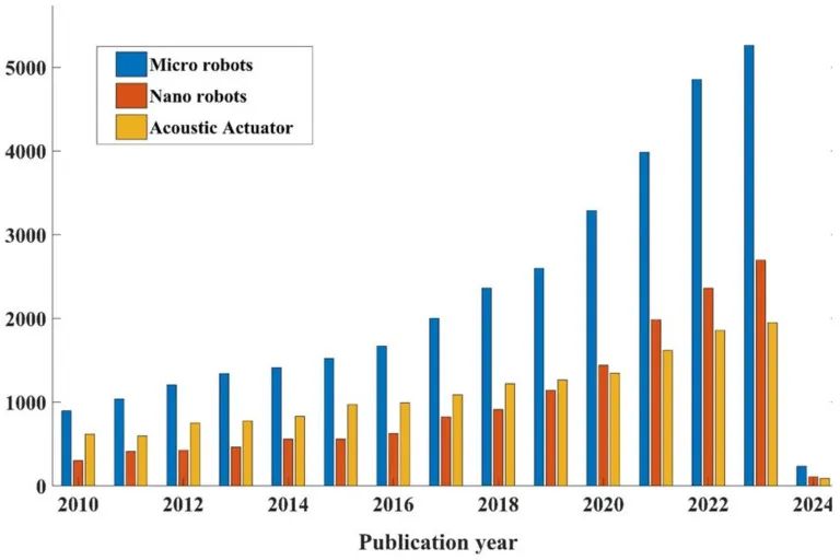
Figure 1
The number of academic articles published from January 2010 to November 15, 2023, using the keywords “microbot,” “nanorobot,” and “acoustic actuator” according to the Science Direct database.
Many methods have been adopted to drive robots and move them to target areas, including biological, chemical, magnetic, and acoustic driving. For biological driving, the navigation of robots to target sites relies on the inherent characteristics of the driving biological cells. Biological driving has advantages such as inherent biocompatible power sources, integrated sensing and targeting capabilities, and suitability for fluid physical environments [24]. However, there are also disadvantages, including limited driving force and relatively weak targeting ability. To improve positioning effectiveness, it is suggested to adopt other positioning strategies. Robots can be propelled by inducing chemical reactions to generate bubbles, thus becoming chemical targets. This propulsion mechanism relies on the catalytic decomposition of hydrogen peroxide, which is present in specific environments. This decomposition occurs through platinum nanoparticles coated on the inner surface of the robot or its payload, forming water and oxygen. This process can generate, form, and release oxygen bubbles from one end, thereby triggering motion in the opposite direction [25]. Although chemical driving methods lead to higher induced propulsion speeds compared to other driving methods, they exhibit poorer directionality and limitations in targeting accuracy, rapid action, and immediate feedback. Moreover, the fuel crucial for the robot is highly toxic, limiting the applicability of this targeting strategy. Magnetic targeting has been emphasized as an effective and widely adopted technology for precise control of robots within target tissues [26]. This method has multiple advantages, including unbound maneuverability, no fuel requirements, and compatibility with other systems. For robots to respond to magnetic fields, magnetic nanoparticles must be incorporated. Two common types of magnetic targeting for robot control are electromagnetic drive (EMA) systems and permanent magnetic drive (PMA) systems. The EMA system consists of electromagnetic coils connected to a power source, which adjusts the coil current through computer software. This setup can generate uniform magnetic fields, magnetic gradients, and/or rotating magnetic fields to manipulate robots. In contrast, the PMA system consists of a set of permanent magnets, with robot control achieved by changing the distance and position of these magnets [27]. Each system has its own advantages and disadvantages. The EMA system can generate magnetic fields in three-dimensional space. Additionally, the magnetic current and frequency can be easily adjusted, providing flexible and precise control. The disadvantages of the EMA system include cost, spatial prerequisites, and heat generation. Compared to the EMA system, the PMA system does not require complex coils, control interfaces, or power sources, thereby alleviating overheating issues. However, the flexibility of magnetic field control is limited, and stopping the magnetic field during operation can be challenging [28].
Due to the generation of strong driving forces, non-physical contact with robots, biocompatible power sources, and the possibility of combining them with ultrasound imaging to track robots, using acoustic actuators for targeting is becoming a powerful MNR manipulation technology. Several review articles have been published, providing comprehensive insights into microbots [3,29,30,31,32,33], nanorobots [34,35,36], and acoustic actuators [36,37,38,39,40,41]. Each review offers researchers unique perspectives and different approaches. In this work, we summarize the latest advancements in the manipulation of MNRs for biomedical applications using acoustic actuators. This research first outlines MNR from fundamentals to applications. Additionally, it describes the principles of acoustic control, which is the primary field application of using acoustic control for MNR in biomedical applications. We then review applications involving the manipulation of different types of MNRs, such as bubble-based microbots, non-bubble microbots, biohybrid microbots, and nanorobots. Finally, we discuss the challenges and potential solutions for MNR manipulation using acoustic signals.
2. Principles of Acoustic Manipulation
2.1. Acoustic Fundamentals
In the context of sound waves, transducers induce vibrations within a medium by converting electrical signals into mechanical oscillations, which are subsequently transmitted through matching layers to the medium. Sound waves are mechanical waves that propagate through a medium (such as solids, liquids, or gases). The characteristics of the medium through which sound waves propagate play a crucial role in adjusting wave acoustic properties. For example, the speed of sound waves in solids is 6000 m/s. In liquids at 20 degrees Celsius, the speed of sound is 1481 m/s. In air at 20 degrees Celsius, the speed of sound is 343 m/s, and at 0 degrees Celsius, it is 331 m/s.
Sound waves have four characteristics: wavelength (m) is the distance between adjacent identical parts of the sound wave, frequency (Hz) is the number of waves passing through a fixed point per second, speed (m/s) is the speed at which sound waves travel through a medium, and intensity (W/m2) is the ratio of the sound energy carried by the wave per unit area in a direction perpendicular to that area [42,43]. Acoustic waves can be classified based on their frequency range as follows:
-
Infrasound: These are sound waves with frequencies less than 20 Hz. They are typically used for applications such as earthquake monitoring and studying low-frequency sound phenomena.
-
Sound waves: This category includes sound waves with frequencies ranging from 20 Hz to 20 kHz, which is the range of human hearing. Sound waves are widely used in various fields such as music, communication, and environmental noise analysis.
-
Ultrasound: Sound waves in the ultrasound range have frequencies from 20 kHz to 200 MHz. They are widely used in medical applications, such as ultrasound imaging, non-destructive testing, and cleaning processes.
-
Hypersound: Sound waves with frequencies above 200 MHz belong to the hypersound category. These waves are primarily used in acoustic microscopy, capable of high-resolution imaging of small-scale structures.
Figure 2a shows the acoustic directory from infrasound to hypersound (less than 20 Hz to over 200 MHz) and its various applications.
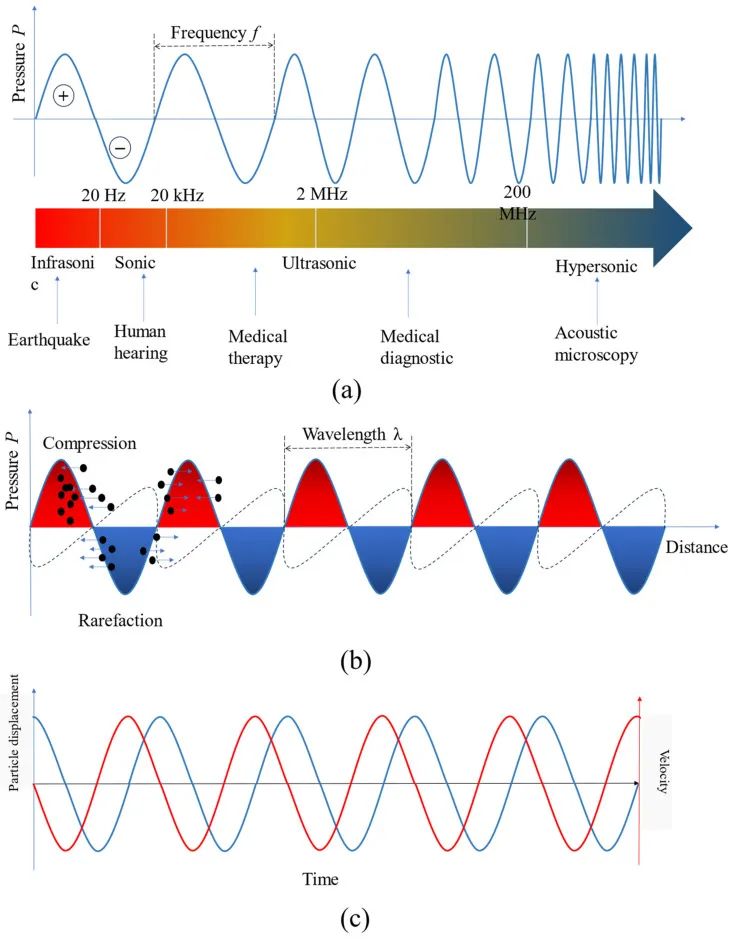
Figure 2
The fundamental characteristics of sound waves: (a) Acoustic directory and its various applications; (b) Sound pressure field formed in the medium; (c) Particle displacement (blue) and velocity (red) in the time domain.
In addition to the four basic parameters of sound waves (such as wave frequency, wave speed, wavelength, and sound intensity), several other key parameters must be considered to fully characterize sound waves. These include particle displacement and velocity, absolute and oscillating sound pressure, density fluctuations (resulting from oscillating pressure), sound attenuation, and acoustic impedance. Sound pressure is a measure of the force exerted by sound waves on a surface perpendicular to the direction of the sound source. It is measured in Pascals (Pa). The oscillation of particles in the medium through which sound waves pass generates pressure fields, leading to periodic regions of compression (high pressure) and rarefaction (low pressure). This region is called a pressure node. Objects immersed in the medium tend to move towards these pressure nodes for stability.Figure 2b illustrates the compression and rarefaction areas relative to the wavelength of sound waves. This fundamental property of sound waves can be used to manipulate targets within the sound pressure field.Figure 2c shows the dependence of particle displacement on velocity. The phase difference between sound pressure and velocity is 0 or 180 degrees, while the phase difference between velocity and displacement is 90 or -90 degrees, depending on the coordinate reference and wave propagation direction. Another acoustic parameter to consider is acoustic impedance, which measures the resistance of a material to sound wave propagation; it is determined by the product of sound speed and medium density.
2.2. Acoustic Radiation Force
When sound waves propagate in gases or liquids, they produce a sound field with varying sound pressures. These pressure differences in the sound field exert forces on immersed or suspended objects, commonly referred to as acoustic radiation force. Additionally, sound waves induce motion in the surrounding medium through a phenomenon known as acoustic streaming.
In the sound field, immersed or suspended objects are influenced by four forces: Fg is the gravitational force acting on the object, Frad is the acoustic radiation force, Fscatter is the acoustic scattering force, and Fstream is the force induced by the flow on the object. Figure 3 illustrates the acoustic radiation force acting on the target object and its dimensions. In summary, the motion of an object in the sound field is described by the following equation:
(1)
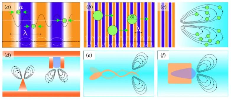
Figure 3
The acoustic radiation force acting on the target object, where a is the dimension and λ is the wavelength of the sound source, with k = 2π/λ defined as the ratio of 2π to the wavelength. Scene (a): The dominant force acting on the target object is the gradient force resulting from the potential sound field U; Scene (b): The scattering force overcomes the gradient force, with the gradient force being the primary force exerted on the target object by the propagating wave; Scene (c): The drag force is the maximum dominant force exerted on the target object by the flow; Scene (d): The flow pattern formed by vibrations; Scene (e): Asymmetric design of micro-swimmers; and Scene (f): Bubble self-propulsion. Reproduced from reference [36]. © 2020 Authors.
2.3. Acoustic Tweezers Propulsion
The working principle of acoustic tweezers propulsion is to generate a geometrical sound field within a defined workspace. In this geometry, the acoustic gradient force acts on the target objects, allowing them to be captured at the desired location. By repositioning or adjusting the acoustic tweezers, the movement of the target objects can be controlled and manipulated to follow the movement of the acoustic tweezers. The two main types of acoustic tweezers propulsion based on the characteristics of the acoustic propulsion mechanism are standing wave tweezers and traveling wave tweezers.
-
Standing wave tweezers
To use standing waves to generate tweezers, sound waves are produced by transducers. Different types of sensors operate on different principles. Standing waves can be further divided into two subtypes: Surface Acoustic Waves (SAW) and Bulk Acoustic Waves (BAW). SAW is generated on the surface of a piezoelectric film by a finger transducer (IDT) fabricated on the surface of the transducer. The characteristics of SAW, such as resonant frequency and amplitude, are identified by the design features of the IDT, such as electrode size, material properties, and applied electrical signals [56–74]. During manufacturing, the IDT is typically made from micro-devices containing electronic and moving parts. These components are very small, with sizes reaching up to 1 micron. Therefore, SAW-based tweezers can be easily integrated with microfluidic systems, making them a versatile tool for lab-on-a-chip applications.
BAW is generated by applying alternating (AC) electrical signals on both sides of the piezoelectric material. This causes sound waves to propagate through the thickness of the material, forming standing waves at specific frequencies [75]. When sound waves are reflected from a reflective layer, they generate standing waves, establishing pressure distributions in the fluid. By adjusting the frequency of the wave according to the dimensions of the channel geometry, the number of pressure nodes and antinodes formed within the channel can be customized.
Due to their high precision acoustic patterns, standing wave tweezers are primarily used for the separation and arrangement of various particles and cells. BAW-based standing wave tweezers have the advantage of processing larger volumes of liquid in a shorter time, making them very suitable for applications such as blood processing in transfusion scenarios [76,77,78]. In contrast, SAW-based tweezers demonstrate higher precision due to the use of higher frequencies, making them more suitable for nanoparticle manipulation and tissue engineering applications [54,57,79,80,81,82,83].
-
Traveling wave tweezers
Traveling wave tweezers generate sound pressure nodes by designing a single beam structure rather than relying on beam interference. This is typically achieved by carefully calculating the phase map on the radiation aperture [61,84,85,86,87,88,89,90,91,92]. The sound wave’s origin can come from a single element or an array of multiple elements, forming traveling wave tweezers. In the case of a single element, an acoustic lens is positioned on the surface of the element. The geometric design of the acoustic lens facilitates the manipulation of the sound focusing field. This approach can generate singular traveling wave acoustic tweezers that meet pre-established parameters. The target objects will be trapped in stable tweezers. To move the target objects, the entire structure (including the transducer and lens) is moved. This feature represents the inherent constraint of traveling wave tweezers derived from a single acoustic element. To overcome this limitation, sound waves can be generated by an array of multiple elements. In this method, phase modulation control algorithms can calculate different delay times for the electrical signals directed to each element. By determining the appropriate delay times, various types of tweezers configurations can be established. The three most popular types of traveling wave tweezers produced by this method are dual tweezers [17,62,93], bottle tweezers [51], and vortex tweezers [61,63,94]. Compared to standing wave tweezers, traveling wave tweezers have greater real-time modulation capabilities and have been shown to be more suitable for in vivo applications.
2.3.2. Flow-driven Acoustics
Acoustic streaming is a stable fluid flow generated by the nonlinear interaction of sound waves with fluid media, typically involving vibrating microbubbles or vibrating solid boundaries. These streams are designed to control the surrounding medium and any MNR immersed in it. Depending on the source of the flow generation, they can be classified into two types: (1) bubble oscillation-based flow and (2) flow based on solid boundary vibrations applied in geometric designs. In bubble oscillation-based flows, bubbles oscillate at their inherent frequencies to generate surrounding fluid vortices. Therefore, they can rotate MNRs at fixed positions and achieve fluid-driven mass transfer enhancement in laminar flow within closed microchannels [95,96,97]. In flows based on solid boundary vibrations, sound waves are reflected onto solid boundaries to induce fluid flow along the boundary. The geometric design of the device is characterized by sharp protrusions or combined symmetric structures. The solid boundaries can be rigid walls, flexible membranes, or microstructures. Although flow-driven acoustics require user-friendly simple acoustic actuators, they are limited to use in liquid media and have lower spatial resolution. Therefore, this technology is primarily used in microfluidic channel technology, fluid management, or rotational operation of biological samples [21,66,97].
3. Acoustic Manipulation of Micro/Nanorobots
Acoustics can operate in a frequency range from kilohertz to gigahertz, facilitating the capture and manipulation of target objects ranging in size from nanometers to centimeters [6,20,98,99,100,101,102,103,104,105,106,107,108,109,110,111,112,113]. In the past decade, global researchers have made significant progress in the acoustic manipulation of micro/nanorobots (MNRs). These developments are at the forefront of transitioning to clinical applications. Huang’s team developed an acoustic platform realized through microfluidic technology that can isolate 110-nanometer particles from complex culture media, with a yield of over 99% [114]. Using SAW tweezers, they separated and analyzed circulating tumor cells (CTCs) from whole blood cells (WBCs), achieving a recovery rate of over 83% [115]. Cao et al. introduced AcoMan, an acoustic manipulation device designed to manipulate nanoclusters in water with five degrees of freedom (5-DoF) [17,62,93]. The transducer array consists of 30 ultrasonic elements, operating at a frequency of 1 MHz and a working voltage of 60 Vpp. AcoMan can manipulate nanoclusters within a working space of 5×5×4 m, with a positioning error of less than 200μm. Additionally, it facilitates the rotation motion of clusters, unrestricted vertically, with a horizontal range of -30.31° to +29.93°. Ghanem et al. developed a manipulable vortex-based acoustic trapping beam capable of lifting and moving a 3 mm glass ball inside a pig bladder [94]. Compared to the expected trajectory, this system can perform 3D motion with a positioning error of less than 10%. No damage was detected on the bladder wall or intervening tissues.
In this section, we discuss the acoustic manipulation of different types of robots, including bubble-based microbots, non-bubble microbots, biohybrid microbots, and nanoparticle-based robots (nanorobots).
3.1. Bubble-based Microbots
Normal living cells are difficult to manipulate with acoustic actuators because these cells have similar acoustic impedance to the medium. To address this issue, Yang et al. genetically engineered bacteria to ensure that numerous submicron-sized bubbles could be induced in the cytoplasm of the bacteria, making the engineered bacteria (GVs@E. coli) sensitive to sound waves and manipulable by sound waves [116]. Using a 64-element acoustic tweezers operating at a working frequency of 3 MHz, the authors guided E. coli GVs@ in the vascular system of living animals in reverse flow or on-demand flow, as shown in acoustic guidance (Figure 4a-f). Due to the interaction of microbubbles with sound waves, integrating microbubbles into microbots allows them to be manipulated by acoustic actuators. In a recent study, Fonseca et al. prepared microbots consisting of lipid shell microbubbles, which could autonomously aggregate and be propelled when exposed to ultrasound [117]. Using a piezoelectric sensor with a resonant frequency of 490 kHz, the authors could control and track microbots in vitro within an artificial vascular system, achieving a movement speed of up to 1.5 μm/s and approximately 10 mm/s of blood flow (Figure 4g, h).
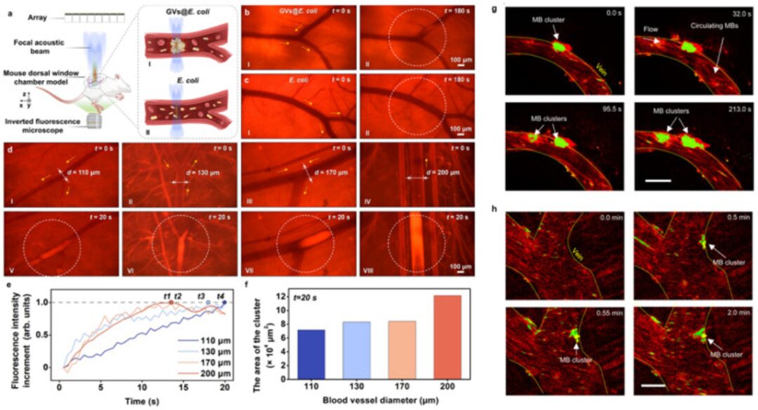
Figure 4
(a) Schematic diagram of the in vivo experimental setup. I and II respectively show the acoustic trapping process of E. coli GVs@ and control E. coli. (b) Comparison of acoustic trapping of GVs@E. coli and control E. coli in superficial blood vessels of mice. I in (b, c) shows microscopic images of blood vessels without ultrasound after injecting E. coli GVs@. II in (b, c) shows the corresponding microscopic images of the blood vessels after exposure to ultrasound for 180 s based on the cases I in (b, c). Only GVs@E. coli can be trapped at the focal beam center and form clusters in the blood vessels. (d) Acoustic trapping of E. coli GVs@ in blood vessels of different diameters. I, II, III, and IV respectively show the microscopic images of blood vessels with diameters of 110, 130, 170, and 200 μm before ultrasound is turned on. V-VIII are the corresponding microscopic images of trapped GVs@E. coli clusters in the respective blood vessels in cases I-IV after 20 seconds of ultrasound activation. The yellow arrows, white dotted circles, symbols (d), and (b-d) indicate blood flow direction, lesion area, vessel diameter, and time, respectively. (e) The curve of normalized fluorescence intensity increases over time in the focal area under different diameter blood vessels shown in (d). T1 to T4 represent the moments when the maximum increment of fluorescence intensity is reached in vessels with diameters of 200, 170, 130, and 110 μm, respectively. (f) The area of clusters of E. coli GVs@ in blood vessels of different diameters (after 20 seconds of ultrasound activation). Reproduced from reference [116] under the terms of the Creative Commons Attribution 4.0 International License. © 2023 Authors. (k, g) Microbubbles (MB) aggregate over time and adhere to the walls of small veins under the acoustic signal at 490 kHz and 35 V. This phenomenon was reproduced in at least ten independent acoustic activation experiments. After image processing, the microclusters were colored bright green and marked with arrows, while the non-responsive individual microbubbles flowing downstream were colored red. Scale bar: 50 μm. Reproduced from [117] under the terms of the Creative Commons Attribution 4.0 International License. © 2023 Authors.
Moreover, microbubbles can be integrated into 3D-printed microstructures for effective operation using acoustic actuators [118,119,120,121,122]. This is possible because the confinement of microbubbles within the cavities of microstructures leads to significant scattering, resulting in powerful propulsion forces when activated by sound waves [123]. 3D printing using two-photon polymerization (TPP) is an emerging technology widely applicable for manufacturing micro/nanoscale robots. TPP allows for simple and precise fabrication of nanoscale robots. Furthermore, the shape and size of the robots can be customized using commercial design software.
3.2. Non-bubble Microbots
Using microbubbles encapsulated in microstructures provides an effective method for manipulating microbots using acoustic transducers. However, the performance of microbots is not stable, as the lifespan of the carried microbubbles is short, only reliably lasting for a few hours, which can trigger gradual switching of the working resonant frequency [124]. Additionally, advanced hydrophobic treatments are needed to retain microbubbles within microstructures. These issues limit the use of bubble-based robots in in vivo applications. Therefore, non-bubble robots with sharp-edged structures allow stable liquid flow when excited by sound waves and are currently attracting researchers’ attention to address the limitations of bubble-based robots. For instance, in their recent study, Deng et al. 3D printed a helical microbot with a length of 350 μm and a diameter of 100 μm, demonstrating that the microbot could move through a finned helical microstructure [123]. Specifically, the microbot exhibited responsive motion to sound stimulation in the frequency range of approximately 13.5 to 18.6 kHz, mimicking the helical motion observed in natural biological bacteria. The asymmetric helical structure interacts with the incident sound field, generating propulsion torque that produces a driving force for rotation around the long axis of the microbot. Interestingly, the microbot has the unique ability to switch direction simply by adjusting the frequency of the sound field. Using a single acoustic piezoelectric transducer connected to a function generator and amplifier, the authors demonstrated motion in two-dimensional and three-dimensional artificial vascular systems (Figure 5a-e). Recently, Wrede et al. introduced the use of hollow borosilicate microparticles characterized by rigid shells, which can be effectively captured and manipulated using single-lens focused ultrasound transducers (operating at frequencies of 2 MHz or 500 kHz) under physiologically relevant flow conditions [125]. These hollow microparticles exhibit stability and good acoustic properties. The authors demonstrated the successful capture dynamics of transducers in circular tubes of different diameters, confirming their effectiveness under realistic flow rates and ultrasound amplitudes. Furthermore, they showcased the ability to displace hollow microparticles by guiding the transducer upstream. Additionally, potential biomedical applications were introduced, including active cell labeling and navigation in bifurcated channels, as well as ultrasound imaging in the liver tissue of mice [Figure 5f-j).
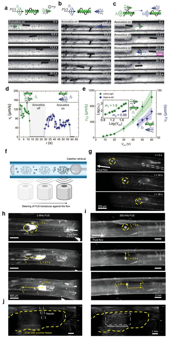
Figure 5
(a–e) Translational motion of microbots in circular microchannels. (a) The microbot responds to external sound waves showing movement from left to right at f1 = 13.5 kHz and 20 V polypropylene. The symbols P(t) in the top schematic diagram indicate pressure waves, while the black arrows show the direction of the sound wave field. (b) The microbot exhibits movement from right to left at f2 = 18.6 kHz and 60 V polypropylene. (c) The microbot demonstrates its bidirectionality by switching from f1 = 13.5 kHz and 20 VPP to f2 = 18.6 kHz and 60 V polypropylene. (d) This figure illustrates the speed curve of the microbot in its bidirectional trajectory. (e) The speeds vt1 (from left to right) and vt2 (from right to left) of the microbot are related to the sound-driven voltage V polypropylene, indicating that the microbot advances at a speed nearly proportional to V polypropylene. The illustration shows the corresponding log-log plot. Note that it is challenging to predict vt2’s scaling due to the lack of data points at higher voltages, as our amplifier limits the maximum voltage to 60 V polypropylene. The gravity direction is opposite to the y-direction, i.e., perpendicular to the plane of the figure. Each data point represents the average speed of at least three microbots. Error bars represent SD. Reproduced from [123] under the terms of the CC BY-NC license. © 2023 Authors. (female, day) Control and retrieval of hollow particles against fluid flow.
(f) Schematic diagram of acoustic manipulation of fluid flow retrieved hollow particles using FUS transducer. (g) Time-lapse images showing the immersion of hollow microparticle clusters in a Tygon tube with a diameter of 4.77 mm at a flow rate of 0.93 mm/s. The particles were captured using a focused 500 kHz ultrasound transducer. The particles were moved back to the injection side using relative motion between the tube and the transducer. There, they were retrieved using a 28 G needle similar to the injection. (h) Movement of hollow microparticles captured by acoustic waves in a tube with a diameter of 500 μm. Here, 100 μL of particles with a concentration of 5 mg/mL were injected into the tube using a 28 G needle. After injection, the particles were captured and moved within the tube using a 2 MHz focused ultrasound transducer. High-speed cameras mounted on an optical microscope were used to image the particles. The applied flow rate was 25.46 mm/s. (i) Capture dynamics of hollow microparticles in a tube using focused 500 kHz sensors. Using a manual x-y-z stage, the particles moved in 2D within the tube. The applied flow rate was 4.67 mm/s. (j) Ultrasound images showing needle positioning (left) and subsequent injection (right) into the hepatic portal vein of an ex vivo mouse liver with multiple liver metastases. The liver region is marked in yellow. Ultrasound imaging was performed in B-mode at a frequency of 40 MHz. Reproduced from reference [125] under the terms of the CC-BY license. © 2023 Authors.
3.3. Biohybrid Microbots
Biohybrid microbots are prepared by hybridizing living cells with synthetic materials. These cells can be immune cells (such as monocytes/macrophages [126], T cells [127], neutrophils [128]), red blood cells [129], or bacteria [130]. The synthetic materials are typically encapsulated with drugs or therapeutic agents as the accompanying payload of the robots. The combination of cells and payloads is achieved through internalization (endocytosis) [131] or through chemical bonding for surface attachment [132]. Wu et al. designed a hybrid microbot that utilizes functionalized magnetic nanoparticles (MNPs) to enter red blood cells (RBCs). The asymmetric distribution of MNPs in RBCs induces net magnetization, allowing the microbots to be simultaneously manipulated by magnetic fields and acoustic propulsion [133]. Using a piezoelectric transducer mounted on a slide, the continuous sine wave operating frequency was tuned in the range of 2.93 MHz with voltage amplitudes adjusted between 0 and 10.0 V, enabling the microbots to achieve speeds exceeding 30 μm/s in PBS. Tang et al. [127] coupled magnetic beads with CAR T cells (Figure 6a, b).
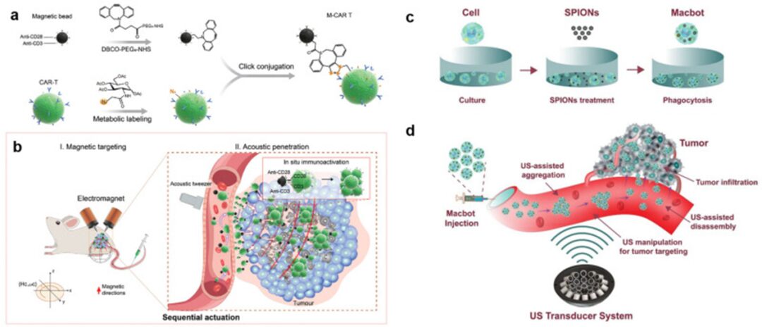
Figure 6
Magneto-acoustic sequential actuation of M-CAR Ts for programmable entity tumor targeting and enhanced immunotherapy. (a) Immunomagnetic beads were modified using DBCO-PEG5-NHS coupling with dibenzocyclooctyne (DBCO) motif and simultaneously labeled with azide sugar Ac4GalNAz to obtain azide-labeled CAR T cells (N3-CAR T). Next, N3-CAR T cells effectively coupled with DBCO-modified beads, producing functionalized M-CAR T through a click chemistry reaction between DBCO and azide groups. (b) Magneto-acoustic sequential driving successfully achieved precise targeting and in situ immunotherapy activity of M-CAR Ts in vivo. Step I (left): Intravenous injection of M-CAR Ts, precisely targeting and accumulating around the tumor edge under the drive of an external gradient magnetic field. The red arrow indicates the magnetic direction. Step II (right): M-CAR Ts accumulated around the tumor are propelled deeper into the tumor by the acoustic force of the tumor-fixed acoustic tweezers, stimulating the proliferation and activation of CAR T cells with anti-CD3/CD28 immunomagnetic beads, thereby achieving a strong anti-tumor effect. Reproduced from reference [127] with permission. © 2023 Wiley-VCH GmbH. Schematic diagram of the concept of targeted tumor therapy using acoustic-driven microbots: (c) The fabrication process of microbots; (d) The working principle of microbots using ultrasound actuator systems. Reproduced from reference [134] under the CC-BY license. © 2022 Authors.
M-CAR Ts are sequentially controlled by electromagnetic fields and acoustic tweezers, with the tweezers consisting of a 3 MHz, 64-element (8 × 8) array capable of generating a focusing vortex acoustic field with a maximum peak-to-peak sound pressure of 1.58 MPa at a stimulation voltage of 30 V. Due to the dual driving in vivo, the authors confirmed a 6.6-fold increase in accumulated CD8+ CAR T cells compared to the number of cells without driving. As a result, the in vivo anti-tumor efficacy in a CD19-SPCA1 tumor-bearing mouse model was improved. Recently, our group used a newly designed acoustic actuator to manipulate macrophage-based biohybrid microbots, proposing a feasible approach for actively targeting tumors for anti-tumor therapy [134]. The acoustic actuator consists of 30 ultrasonic transducers operating at 1 MHz, creating a dual trap configuration at the capture point. These microbots are fabricated by hybridizing macrophages with magnetic nanoparticles, which serve as therapeutic payloads for the microbots. When exposed to the sound field, a group of microbots can be precisely guided along predetermined paths, allowing them to approach the target from various angles.
Thus, we successfully controlled the microbot cluster to reach any point within a region of interest measuring 4×4×4 mm, with a positioning error of less than 300 μm, which is impressive. Moreover, the cluster demonstrated the ability to rotate within the O-XY plane at 45° intervals, with no restrictions on the overall angle range (Figure 6c, d).
3.4. Nanorobots
Although the manipulation of nanorobots using acoustic actuators has not been extensively studied in the literature, the feasibility of this approach has been demonstrated. In a pioneering study, Li et al. prepared a hybrid nanorobot (nano-motor) with one end consisting of concave gold (Au) nanorods and the other end of nickel (Ni)-coated palladium (Pd) helical nanowires (Figure 7a-c). The concave gold nanorod structure enables effective acoustic manipulation, while the nickel-coated helical nanowire allows the nanorobot to be controlled within a magnetic field [135]. Thus, the nanorobot can switch its operational mode by toggling between acoustic and magnetic signals. Under acoustic manipulation, the nanorobot can achieve speeds of 22.3 μm/s at an applied voltage of 6 V. In a recent study, we employed an acoustic transducer system comprising 30 ultrasonic transducers, operating at a resonant frequency of 1 MHz, with controllable peak-to-peak voltages ranging from 10 to 200 V, arranged on one side to generate active traveling waves [17]. These waves were used to manipulate the position and orientation of unbound nanorobots within a spherical working space in water, allowing for three degrees of freedom in translation and two to three degrees of freedom in rotation. Phase modulation algorithms were applied to independently control the phase signals of each transducer, enabling precise manipulation of the position of the nanorobots. The feasibility of this method was demonstrated through in vitro and ex vivo experiments involving pig ribs (Figure 7d–g) andTable 2 summarizes the different types of acoustic actuators used for operating MNRs and their applications.
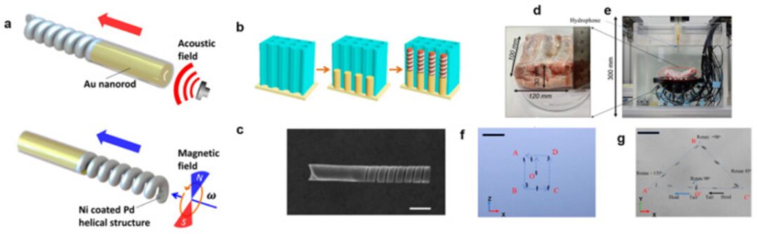
Figure 7
(a) Design scheme of the magneto-acoustic hybrid nanomotor and its dual propulsion modes under acoustic and magnetic fields. (b) Schematic diagram of the template-assisted fabrication of the segmented magneto-acoustic hybrid nanomotor. (c) SEM image of the magneto-acoustic hybrid nanomotor. Scale bar: 500 nm. Reproduced from reference [135] with permission. © 2015 American Chemical Society. (d-g) In vitro experiments for testing the manipulation and rotation of nanocarrier clusters: (d) Size of pig ribs; (e) Experimental setup; (f) Time-lapse images of manipulation in the XOZ plane; (g) Time-lapse images of operation and rotation in the XOY plane (scale bar: 2 mm). Reproduced from reference [17] under the terms of the CC-BY license. © 2022 Authors.
Table 2
Manipulation of different types of acoustic actuators for the operation of MNRs and specific applications.
| No. | Type of Acoustic Actuator, Operating Frequency | Type of Robot | Application | Reference |
|---|---|---|---|---|
| 1 | 30 ultrasonic transducer array, active traveling wave, 1 MHz | Nanorobots | 3D operation | [17] |
| 2 | Piezoelectric disk transducer, 237 kHz | Bubble-based microbots | 3D operation | [39] |
| 3 | Ultrasound 16 transducer array, active traveling wave, 1 MHz | Non-bubble microbots | 3D operation, targeted drug delivery | [62] |
| 4 | Piezoelectric transducer, 4.6 kHz | Non-bubble microbots | Remote driving | [71] |
| 5 | 64-element array acoustic tweezers, 3 MHz | Bubble-based microbots | In vivo tumor targeting | [116] |
| 6 | Piezoelectric sensor, 490 kHz | Bubble-based microbots | In vivo operation | [117] |
| 7 | Piezoelectric transducer, 70–270 kHz | Bubble-based microbots | Multi-degree motion, cancer cell lysis | [118] |
| 8 | PA1951 sensor, 50–120 kHz | Bubble-based microbots | Debris removal, cell collection | [119] |
| 9 | Ceramic piezoelectric transducer, 320 kHz | Bubble-based microbots | Epithelial fixation and drug delivery | [122] |
| 10 | Piezoelectric sensor, 12−19 kHz | Non-bubble microbots | 2D, 3D operation | [123] |
| 11 | Piezoelectric sensor, 5–270 kHz | Non-bubble microbots | Biological operation, targeted therapy | [124] |
| 12 | Focused ultrasound sensor, 500 kHz and 2 MHz | Non-bubble microbots | Active cell labeling, navigation, and ultrasound imaging | [125] |
| 13 | 64-element array acoustic tweezers, 3 MHz | Biohybrid microbots | In vivo operation, anti-cancer therapy | [127] |
| 14 | Piezoelectric transducer, 2.93 MHz | Biohybrid microbots | Therapeutic transport | [133] |
| 15 | 30 ultrasonic transducer array, active traveling wave, 1 MHz | Biohybrid microbots | 3D operation, targeted drug delivery | [134] |
| 16 | Piezoelectric sensor, 618 kHz, 2.66 MHz | Nanorobots | Autonomous reconfiguration operation | [135] |
| 17 | Piezoelectric ceramic actuator, 4.6 kHz | Bubble-based microbots | 3D maneuverability | [136] |
| 18 | Immersion ultrasound transducer, 234 kHz, 301 kHz | Bubble-based microbots | Targeted delivery, remote microsurgery | [137] |
| 19 | Piezoelectric transducer, 28.0 kHz | Non-bubble microbots | Acoustic-magnetic manipulation | [138] |
| 20 | Piezoelectric transducer, 20–100 kHz | Non-bubble microbots | Similar particle capture | [139] |
| 21 | Piezoelectric transducer, 22.3−23 kHz | Bubble-based microbots | Train-like assembly and cargo transport | [140] |
| 22 | Piezoelectric sensor, 4.25 MHz | Bubble-based microbots | In vivo operation | [141] |
| 23 | Piezoelectric ceramic transducer, 1 to 3 MHz | Bubble-based microbots | Single particle manipulation | [142] |
Chapter 4: Challenges and Future Perspectives
As a promising method for manipulating MNRs, acoustic manipulation is still in an immature development stage, although it has been applied in many research areas of biomedical applications. However, there are still many challenges associated with this technology in biomedical applications, which can be highlighted in two main categories based on the acoustic propulsion source and the following aspects of MNRs: (1) Micro/nanorobotics is an emerging interdisciplinary field that encompasses various scientific disciplines, including mechanics, electronics, materials, biology, and others. Therefore, achieving the potential applications of MNRs in the biomedical field requires collaborative efforts from researchers across these different disciplines to overcome inherent challenges. (2) Regarding the current manufacturing technologies for MNRs, the available material choices are still very limited. Thus, the potential biomedical applications are restricted by the materials of MNRs. (3) The biodegradability and biocirculation of these materials still pose challenges in practical biomedical applications.
Issues related to sound source propulsion are as follows: (1) The primary challenge of using acoustic-driven MNRs is their application in complex media, such as the human body. The differences in acoustic impedance between various materials that sound energy must traverse before reaching the target can significantly reduce its energy and even alter its properties. This issue poses a significant barrier that needs to be addressed to make acoustic driving of MNRs more effective. (2) Currently, the second main challenge of acoustic actuation is the limitations in spatial and temporal resolution of acoustic actuators. While using higher frequencies allows for smaller target control, it reduces acoustic penetration. Therefore, many researchers are investigating metamaterials and phononic crystals to improve the precision of acoustic actuators. (3) In biomedical applications, safety and avoiding harm to the target is of utmost importance. However, sound energy can harm the target through generated heat and acoustic cavitation. To avoid these issues, research and the establishment of standardized methods for characterizing the effects of sound waves on specific organs and frequencies are needed. This way, researchers can ensure that the technology is compatible with their research goals.
Additionally, most existing studies have adopted single or few commercial piezoelectric actuator arrays, which generate small driving forces and may limit the flexibility and workspace of the actuation system. This reduces the applicability of acoustic driving systems compared to other types. Therefore, future research should focus on developing acoustic actuation systems with stronger driving forces and larger workspaces, and should include imaging capabilities. In terms of manipulation capabilities, although the feasibility of manipulating MNRs has been well established in the literature, directional controllability remains challenging. Recently, Deng et al. demonstrated the possibility of controlling the orientation of helical microbots in simple 3D channels with different inclination angles [123]. Thus, to achieve effective directional manipulation of microbots, combining with other driving methods (such as magnetic fields) may be beneficial [143]. Additionally, simple open-loop control has been highlighted. Future research could focus on feedback controllability, allowing for the precise manipulation of such robots to target areas. Additionally, more complex environments should be tested to demonstrate meaningful biomedical applicability. Real-time tracking and visualization of MNRs in vivo also remain challenging and require further research. Finally, the design of MNRs is still too simplistic, and the biodegradability and biocirculation of these MNRs remain limitations for