4 Network Layer IP
The transmission of packets mainly goes through Application Layer, Transport Layer, Network Layer, and Link Layer. Following the explanation of the application layer HTTP and Transport Layer TCP, the application layer data is encapsulated by the transport layer and then needs to be encapsulated by the network layer. The core task of the Network Layer is to enable communication between hosts. Before discussing the IP layer, many foundational concepts need to be laid out.
4.1 IP Basics
4.1.1 Definition of IP
In real life, people can find each other because they know each other’s detailed addresses. In a network, to communicate, one must know the other’s IP address. IPv4 is represented by 32 bits of binary data, with every 4 bits forming a group, converted into decimal data, separated by ..

4.1.2 IP Classification
To facilitate addressing and hierarchical network construction, IP addresses are divided into five classes: A, B, C, D, and E.
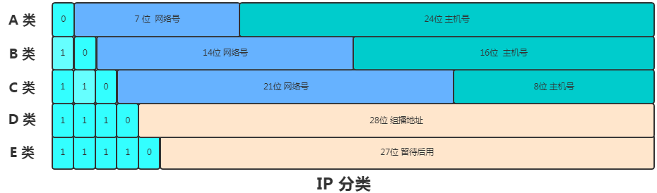

In classes A, B, and C, the IP address consists of a network number and a host number. The commonly stated formula is IP address = Network Address + Host Address. Each of these classes has a few fixed bits representing different types, and if the network number is all 0, the network is unavailable. The host bits of the network address that are all set to 1 are marked as broadcast address, while all bits set to 0 indicate the host address, which refers to all hosts in that network.
Broadcast Address
The Broadcast Address refers to sending messages simultaneously to all hosts on the local area network. For example, 136.78.255.255 is a broadcast address in class B. If you send information to this address, it is sent to all hosts with the network number 136.78.
Broadcasting within the same network is called local broadcast, and the IP packets sent from this broadcast address will be filtered by the router.
Broadcasting between different networks is called direct broadcast.
Host Address
In a network segment, when the host number is all 0, it represents the network segment itself, known as the network number. This address cannot be assigned to a host.
Multicast
The
multicastin class D is used to send packets to all hosts in a specific group.The one-to-one communication mode between hosts is called
unicast, while the one-to-all communication mode is calledbroadcast, and the one-to-a-group communication mode is calledmulticast.
4.1.3 Subnet Mask
Subnet Mask, also known as Network Mask or Address Mask, has only one function: to divide an IP address into network address and host address.
-
The subnet mask is a 32-bit address used to mask part of the IP address to distinguish between network identification and host identification, indicating whether the IP address is on a local area network or on a remote network.
-
The host number part of the subnet mask is all 0, while the non-host number part is all 1.
-
The subnet mask cannot exist independently; it must be used in conjunction with the IP address.
-
Using the subnet mask, one can determine whether two IPs are within the same local area network.
-
The subnet mask reveals how many bits are for the network number and how many bits are for the host number.
The subnet mask can be used to obtain the network address and host address.
-
Convert the IP address and subnet mask into binary.
-
Perform a ‘AND’ operation on the binary form of the IP address and the subnet mask, converting the result to decimal to obtain the network address.
-
Invert the binary form of the subnet mask.
-
Perform an
ANDoperation between the inverted subnet mask and the IP address, converting the result to decimal to obtain the host address.
Subnet masks are generally divided into two categories: the first is the system default:
The subnet mask for class A addresses is 255.0.0.0.
The subnet mask for class B addresses is 255.255.0.0.
The subnet mask for class C addresses is 255.255.255.0.
The second category is custom subnet masks, which divide a network into several subnets, requiring each segment to use different network numbers or subnet numbers. In practice, this can be seen as dividing the host number into two parts: subnet number and subnet host number. The format is as follows:
The IP address without subnet division: network number + host number; after subnet division: network number + subnet number + subnet host number.
In other words, after subnetting, part of the previous host number is given to the subnet number, while the remainder is the subnet host number.
4.1.4 Classless Addressing
Advantages of Classful Addressing:
-
Simple and clear; one can judge based on the fixed values of the first few bits.
Disadvantages of Classful Addressing:
-
In reality, you may find that class C addresses have a limited maximum number of hosts, while class B has too many, making IP allocation poorly match actual network needs.
-
There is no address hierarchy within the same network; for example, if a company uses a class B address, but its production, testing, and development segments need different address hierarchies. This cannot be achieved.
Since classful addressing leads to so many inconveniences, people later proposed a classless addressing scheme, which divides the 32-bit IP address into two parts: the front part is the network number, and the back part is the host number.
For example, 10.100.34.33/24, this address representation is CIDR, where /24 indicates that the first 24 bits are the network number, and the remaining 8 bits are the host number. At this point, the following information is available:
-
Subnet mask: 255.255.255.0
-
Network number: 10.100.34.0
-
Available address range: 10.100.34.0 ~ 10.100.34.255
-
Broadcast address: 10.100.34.255
4.1.5 Private IP and Public IP
Private IP: Generally used within a local area network, different local area networks may have the same private IP address. When a computer wants to access the internet, it must use a public IP; private IPs are not allowed. Public IP: There is only one public IP in the world, and accessing the internet requires a public IP as an identity identifier. Public IPs are managed by the Inter NIC Internet Information Center. These IP addresses are allocated to organizations that register and apply to the Inter NIC.
4.2 IP Layer + MAC Layer Basic Information
4.2.1 ARP and RARP
After TCP processes the data, the next step is to determine the next hop for the IP packet through the host’s routing table or the router’s routing table. Here, it is important to note that the lowest layer of data transmission is the link layer, which transmits based on MAC addresses. Thus, the question becomes how to obtain the next hop’s MAC address using the target IP.
The Address Resolution Protocol (ARP) is the protocol used to resolve IP addresses to MAC addresses. The main tasks of the ARP protocol include establishing, querying, updating, and deleting ARP table entries.
ARP introduces the concept of an ARP cache table, where each host or router maintains an ARP cache table that contains the mapping of IP addresses to MAC addresses. The entries in the table are known as ARP table entries, and the data typically includes a TTL attribute, defaulting to 10 minutes. You can view the ARP cache table information on a server using arp -a.
ARP Workflow:
-
The host sends an ARP request packet via broadcast, containing the IP address of the host whose MAC address it wants to know.
-
All hosts within the same local area network receive this request. If the target IP address matches the IP address of the host receiving the ARP request, it will respond with an ARP reply, providing the target MAC address, and then send the data.
-
If the target IP is not in the same local area network, it will hop to the router, first checking the routing table. If it finds the target MAC, it returns; if not, the router continues to hop down, requesting the MAC address at each hop until the data is sent to the target MAC address’s host. This is how data is ultimately sent to the target machine through a
hop-by-hopmethod. -
The operating system typically caches the first MAC address obtained through ARP for future direct retrieval of the corresponding MAC address from the cache.
-
Throughout the entire data transmission, you will notice that the source IP and target IP remain unchanged; what changes is the MAC address, as the link layer requires MAC addresses for packet transmission between two devices in Ethernet.
RARP functions oppositely to ARP; it is used to obtain an IP address given a known MAC address. For instance, small devices like printers may obtain their IP addresses through their MAC addresses. The workflow of RARP is as follows:
-
The host sends a local RARP broadcast that reaches all devices on the local network, declaring its MAC address and requesting any RARP server receiving this request to assign it an IP address.
-
The RARP server on the local segment receives this request and checks its RARP list to find the corresponding IP address for that MAC address;
-
If it exists, the RARP server sends a response data packet to the source host, providing it with that IP address. If it does not exist, the RARP server does not respond.
-
The source host uses the obtained IP address for communication upon receiving the response from the RARP server. If a response is not received, it indicates that initialization has failed.
4.2.1 Network Interface Card MAC
ARP seeks MAC addresses, which are found on the network interface card. The Network Interface Card operates at the link layer and serves as the interface connecting computers to the transmission medium in a local area network. The network cable connects to the NIC, which is plugged into the computer’s motherboard, facilitating internet connectivity.
The important component of the NIC is the MAC, or Media Access Control address, which is a 6-byte data encoded in the NIC and has global uniqueness, similar to a person’s ID number. The NIC also contains a processor and memory, including RAM and ROM, and performs the following functions:
-
Data encapsulation and decapsulation.
-
Link management, automatically handling erroneous frame data.
-
Encoding and decoding, processing data sent to the network and interpreting data received from the network.
After the IP layer obtains the MAC address, the NIC needs to convert digital signals to electrical signals. The NIC generally operates through a NIC driver. Here’s a brief overview of the NIC workflow:
-
After the NIC receives data from the IP layer, it copies the data to the NIC buffer.
-
It adds headers and start frame delimiters to indicate the start of the packet and appends a frame check sequence at the end to check if the packet is damaged.
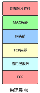
Physical Layer Data Frame -
Finally, the NIC sends the final electrical signal out.
4.2.3 Relationship Between IP and MAC
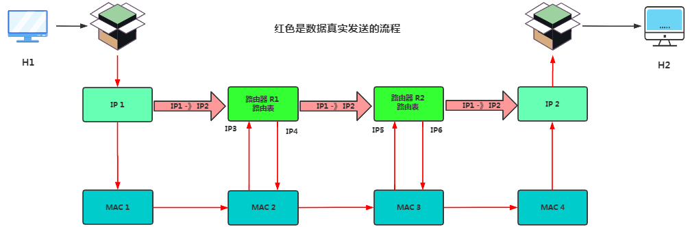
-
Host H1’s network layer datagram transfers the data to MAC1 via the ARP protocol, then the data is encapsulated into a frame and sent to MAC2.
-
Router R1 receives the MAC frame from MAC2, transmits it to the network layer, and decapsulates the MAC frame header to obtain clean data, then sends it to MAC3.
-
Router R2 receives the MAC frame from MAC3, transmits it to the network layer, and decapsulates the MAC frame header to obtain clean data, then sends it to MAC4.
-
The target router receives the information packet, continuously unpacks it, and ultimately sends the data to H2.
-
During transmission, data flows from the upper layers down to the lower layers before being transmitted over the communication link. The IP datagram using the IP address is encapsulated with MAC addresses when handed over to the data link layer. In actual transmission, both the source and destination addresses used are MAC addresses.
One might wonder, since MAC addresses are unique, why not use MAC addresses directly instead of IP addresses? There are various types of MAC addresses distributed globally. An IP address is like a house number, while a MAC address is like an ID number. Knowing just the ID number requires searching globally, but knowing the IP address is like knowing a person’s detailed address in the world, allowing for quicker tracking.
The IP layer abstracts away the complexities of the lower layers, allowing users to discuss issues at an abstract network layer, using a unified and abstract IP address to study communication between hosts or between hosts and routers. Simply put, having an IP address allows one to find the destination host through a router, abstracting the heterogeneous nature of the lower-level network, with MAC addresses completing the actual forwarding at the lower level.
4.2.4 Gateway and Modem
Gateway
-
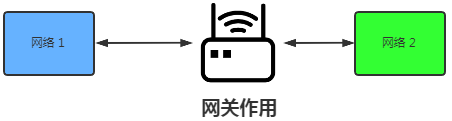
To move from one room to another, one must pass through a door. Similarly, to send information from one network to another, it must pass through a gateway, which is a network connection point between two different networks.
-
The concept of a gateway is logical; it is a broad concept and does not specifically refer to a type of product. Any device that connects two different networks can be called a gateway, whether local or wide area.
-
A gateway is essentially an IP address that connects one network to another; different network segments communicate through the gateway.
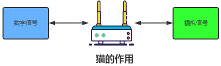
Modem
-
Is a type of computer hardware, commonly known as a
modem, which converts the digital signals that the computer wants to send into electrical pulse signals in the network cable, allowing information to be transmitted through the cable. In the early days, modems were often used over telephone lines, with maximum speeds generally not exceeding 56kpbs, and they are now rarely used.
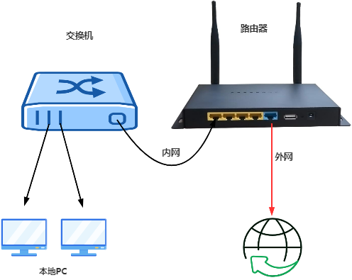
4.2.5 Switch and Hub
Data reaches the switch after being processed by the NIC. The switch operates at the MAC layer and is also known as a Layer 2 network device.
-
Function: The switch connects multiple terminals (computers, phones, printers) and helps forward data between them, suitable for interconnection within a local area network.
-
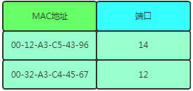
Principle: The forwarding principle of the switch is to record the MAC addresses of each terminal and which interface corresponds to each MAC address. When information arrives, it checks the table for navigation. It is important to note that the switch does not have a MAC address.
MAC If the MAC address table lookup fails to find the required information, the switch will broadcast the packet to all ports except the source port, and the target port will automatically receive the data, while non-target ports will filter out the garbage data. It is worth noting that both MAC and IP addresses have special broadcast addresses. The following two are broadcast addresses:
MAC = FF:FF:FF:FF:FF:FF
IP = 255.255.255.255
Hub:
-
A signal received at one port is sent unchanged to all other ports, leaving the devices on the other ports to decide whether to accept the signal. This is somewhat similar to broadcasting but is more pure than broadcasting.
4.2.6 Router
After data passes through the switch, if the target IP is not in the local area network, it must find the router. The router, or Router, generally refers to a specific type of product that can achieve routing and forwarding. Clearly, the router can perform the function of a gateway. Generally speaking, routers serve as hubs connecting different networks, forming the main framework of the TCP/IP-based international internet network, or in other words, the skeleton of the internet.
Routers determine the output port and next hop address based on the network layer address in the received data packet and the routing table maintained internally, and they rewrite the link layer data packet header to forward the data packet. Routers generally provide the following functions:
-
Network Interconnection: Enabling communication between different networks.
-
Path Selection: Finding the best transmission path for each data frame passing through the router.
-
Data Processing: Providing packet filtering, forwarding, prioritization, firewall, etc.
-
Network Management: Providing configuration management, performance management, traffic control, etc.
Routers perform two tasks that ordinary switches cannot:
-
Interconnecting Different Subnets: Each host has its own IP address, which is subnetted. To interconnect different subnets, routers must be used. Players from different regions will have different subnet IP addresses.
-
Network Address Translation: Hosts in internal networks or internet cafes use private IP addresses, and private IP addresses cannot access the internet. To access the internet, they must be converted to public IPs. Address conversion is also done by routers.
Routers are designed based on IP, commonly referred to as Layer 3 network devices. Each port of a router has a MAC address and an IP address. The router checks the data frame’s destination address field for the data link identifier. If it contains the router interface identifier or the broadcast identifier, the router will strip the data packet from the frame and pass it to the network layer.
When the router receives electrical signals, they are also converted into digital signals, followed by FCS checks. If the sender’s MAC address matches its own, the frame is accepted; otherwise, it is discarded.
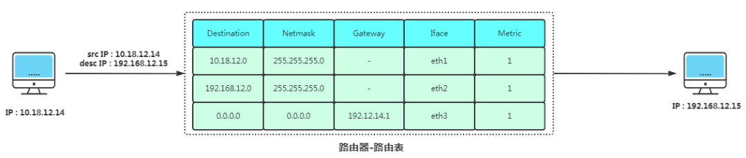
Based on the target IP and Routing Table, the router decides how to forward the information. The routing table stores subnet marking information, the number of routers on the internet, and the names of the next routers. The routing table can be fixed by system administrators or dynamically modified. It can be automatically adjusted by routers or controlled by hosts. Linux servers generally use route -n to query the current routing table.
-
Compare the destination IP with each row in the routing table using a bitwise AND operation with the Netmask to obtain the target IP, checking which row’s Destination matches.
-
Upon finding the target row, use the Gateway and corresponding network interface (Iface) to proceed.
If the Gateway is not empty: it indicates that the Gateway is still needed for further routing transmission.
If the Gateway is empty: it indicates that the target address in the IP packet header has been found, reaching the endpoint.
Perform an ARP request, first attempting to convert from the routing cache, then sending an ARP request to replace the header MAC address.
Convert digital signals to electrical signals, then send the data out.
The data reaches the next router through the switch, continuing until it reaches the target address.
The last line of Destination and Netmask is 0.0.0.0, indicating the default gateway. If no other entries can match, it will automatically match this line and subsequently send the packet to the Gateway.
4.2.7 DHCP
Dynamic Host Configuration Protocol is a local area network protocol, which is an application layer protocol. When we set the client host’s IP address to be dynamically obtained, the DHCP server assigns an IP address to the client based on the DHCP protocol, eliminating the need for users to set IP addresses and subnet masks, allowing the client to use this IP to access the internet.
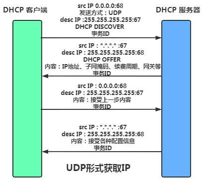
Briefly, the DHCP interaction process is as follows:
-
Since the client does not have an IP address, it sends a DHCP Discover packet using
UDPbroadcast throughout the process. -
The server responds with a DHCP Offer packet, providing details such as IP address, subnet mask, default gateway, and IP lease duration.
-
The client selects one of the numerous responses to configure and sends a DHCP Request packet to the selected server requesting the assigned IP.
-
Upon receiving the Request packet, the server responds with a DHCP ACK message confirming the requested parameters.
-
It is important to note that UDP broadcasts only occur within a local area network. So does each local area network need a DHCP server? To solve this, the system introduces
DHCP relay agents, allowing a single DHCP server to manage IP address allocation across different subnets.
DHCP is typically applied in large local area network environments, mainly serving to centrally manage and allocate IP addresses, enabling hosts in the network environment to dynamically obtain IP addresses, Gateway addresses, DNS server addresses, etc., thus improving address utilization.
4.2.8 NAT
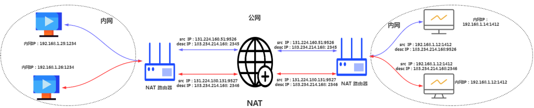
When a server with a private IP wants to access the internet, it needs to be converted to a public IP to communicate with the outside world. The Network Address Translation is responsible for this. However, it should be noted that NAT only implements IP conversion, so it does not solve the problem of expanding IPv4. NAPT can perform address and port conversions together. This allows multiple computers to share a single public IP, a technique known as network address and port translation.
This conversion uses the NAPT router’s conversion table, which is generally automatically generated and maintained by the router.
Disadvantages:
-
If the NAT router restarts during communication, the TCP connection must be reset.
-
The production and conversion of the NAT table must be generated and maintained.
-
Public IPs cannot actively connect to NAT internal servers because the NAPT table does not record them.
Solutions:
-
NAT Traversal Technology: This technology allows network programs to actively discover their location on NAT devices, obtain the public IP of the NAT device, and then establish the NAPT table.
-
Switch to IPv6: 128 bits of binary are definitely enough for the terminals on Earth.
4.2.9 ICMP
Internet Control Message Protocol (ICMP) is a sub-protocol of the TCP/IP protocol suite, used for transmitting control messages between IP hosts and routers. Control messages include network connectivity, host reachability, and route availability. When you ping to check network connectivity, the underlying mechanism is based on ICMP.
ICMP provides consistent and understandable error report information. Error packets sent back to the device that sent the original data allow the sending device to determine the type of error that occurred and decide how to resend the failed data packets more effectively. However, ICMP’s sole function is to report problems, not to correct errors, which is the sender’s responsibility.
ICMP is generally divided into two categories:
-
Query message types: Used for diagnostic query messages.
-
Error message types: Notify the sending device of the cause of the error.
In IPv4, ICMP plays a supplementary role in supporting IPv4. That is to say, during the IPv4 era, even without ICMP, IP communication could still be achieved. However, in IPv6, ICMP’s role has expanded; without ICMPv6, normal communication in IPv6 would not be possible.
4.3 IP Layer Analysis
4.3.1 Meaning of the IP Header
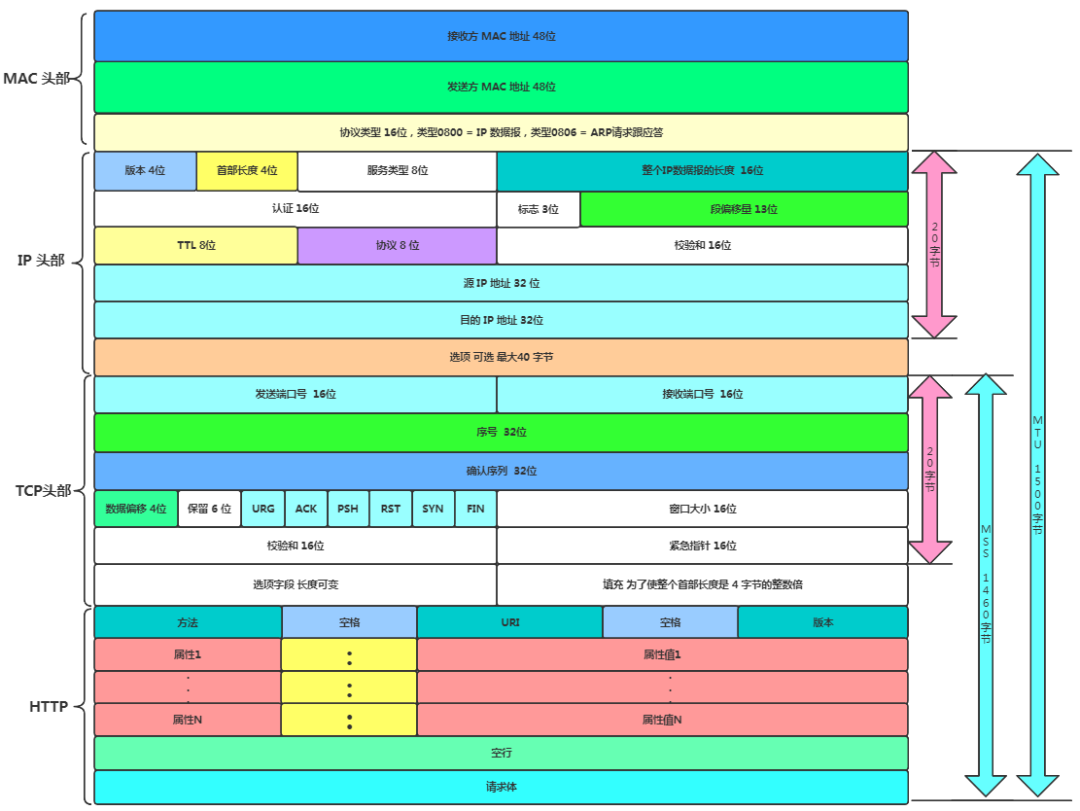
Having explained the essential knowledge of the IP layer and link layer, it is much easier to understand the transition of data from TCP to IP. Here, we will roughly discuss the core IP header fields in IPv4.

-
Version Number: A 4-bit version indicating the version of the IP protocol. For IPv4, its value is 4. Other extended versions of the IPv4 protocol (like SIP and PIP protocols) have different version numbers (their header structures also differ from that of IPv4).
-
Header Length: A 4-bit header length indicating how many 32-bit words (4 bytes) the IP header contains. Since a 4-bit field can represent a maximum of 15, the longest IP header is 60 bytes.
-
Type of Service: An 8-bit Type of Service (TOS) field, including a 3-bit priority field (now ignored), a 4-bit TOS field, and a 1-bit reserved field (must be set to 0). The 4-bit TOS field can indicate: minimum delay, maximum throughput, highest reliability, and lowest cost. At most, one can be set to 1, and applications should set this according to their actual needs. For example, login programs like SSH and Telnet require minimum delay service, while file transfer programs like FTP require maximum throughput service.
-
Total Length: A 16-bit total length indicating the length of the entire IP datagram in bytes, so the maximum length of an IP datagram is 65535 bytes (2^16-1). However, due to MTU limitations, datagrams exceeding the MTU will be fragmented during transmission, so the actual transmitted IP datagram (or fragments) length is far less than the maximum value. The next three fields describe how fragmentation is implemented.
-
Identification: A 16-bit identification uniquely identifies each datagram sent by the host. Its initial value is randomly generated by the system; each time a datagram is sent, its value increments by 1. This value is copied to each fragment during fragmentation, so all fragments of the same datagram have the same identification value.
-
Flags: A 3-bit field where the first bit is reserved. The second bit (Don’t Fragment, DF) indicates whether fragmentation is prohibited. If this bit is set, the IP module will not fragment the datagram. In such cases, if the IP datagram length exceeds the MTU, the IP module will discard the datagram and return an ICMP error message. The third bit (More Fragment, MF) indicates whether there are more fragments. All fragments except the last one must set this to 1.
-
Fragment Offset: A 13-bit fragmentation offset indicates the offset relative to the start of the original IP datagram (referring only to the data portion). The actual offset value is obtained by left-shifting this value by 3 bits (multiplying by 8). For this reason, all IP fragments except the last one must have a data portion length that is a multiple of 8 (to ensure subsequent IP fragments have a suitable offset).
-
Time to Live: An 8-bit Time To Live (TTL) indicates the number of router hops the datagram is allowed to take before reaching its destination. The TTL value is set by the sender (commonly 64). As the datagram is forwarded, this value is decremented by 1 for each hop. When the TTL value reaches 0, the router will discard the datagram and send an ICMP error message to the source. The TTL value prevents datagrams from getting stuck in routing loops.
-
Protocol: An 8-bit protocol used to distinguish upper-layer protocols, as discussed in Chapter 1. The /etc/protocols file defines the values corresponding to all upper-layer protocols. ICMP is 1, TCP is 6, and UDP is 17. The /etc/protocols file is a subset of RFC 1700.
-
Header Checksum: A 16-bit header checksum filled by the sender, which the receiver uses the CRC algorithm to verify whether the IP datagram header (note: only the header) is damaged during transmission.
-
Source and Destination IP Addresses: 32 bits used to identify the sender and receiver of the datagram. Generally, these two addresses remain unchanged throughout the transmission of the datagram, regardless of how many intermediate routers it passes through.
-
Options Field: The options field is variable in length and can contain up to 40 bytes, as the maximum IP header length is 60 bytes (including the previously discussed 20 bytes of fixed parts). Available IP options include
Record Route: The record route option tells all routers that forward the datagram to fill in their IP addresses in the IP header’s options section, allowing us to track the path of the datagram.
Timestamp: The timestamp option tells each router to fill in the time (or time with IP address) the datagram was forwarded into the IP header’s options section, enabling measurement of the time taken for the datagram to travel between routers.
Loose Source Routing: Loose source routing specifies a list of router IP addresses that the datagram must pass through during transmission.
Strict Source Routing: Strict source routing is similar to loose source routing, but the datagram may only pass through the specified routers.
4.3.2 IPv6
IPv4 addresses are 32 bits long, providing approximately 4.2 billion addresses, but by 2011, IPv4 addresses had been fully allocated. Thus, IPv6 was proposed, which features 128-bit addresses, offering a better network experience compared to IPv4.
IPv6 addresses are 128 bits long, grouped every 16 bits and separated by :. If there are consecutive 0s, these can be omitted and represented with two colons ::. However, a single IP address can only contain two consecutive colons once.

-
Version: Like IPv4, this is 4 bits long. The version number for IPv6 is 6, so the value in this field is 6.
-
Traffic Class: Equivalent to the TOS (Type of Service) field in IPv4, also 8 bits long. Although TOS achieved little in IPv4 and was planned to be removed in IPv6, it was retained for future research considerations.
-
Flow Label: Composed of 20 bits, intended for quality of service control.
-
Payload Length: This indicates the length of the packet’s data portion. In IPv4, TL (Total Length) refers to the entire length, including the header. However, in IPv6, this payload length does not include the header, only indicating the length of the data portion.
-
Next Header: Corresponding to the protocol field in IPv4, this is 8 bits long, usually indicating that the upper-layer protocol is TCP or UDP. However, in cases with IPv6 extension headers, this field indicates the protocol type of the first extension header following it.
-
Hop Limit: Also 8 bits long, equivalent to TTL in IPv4. This emphasizes the concept of the number of routers that can be traversed, hence the name change to Hop Limit. Each time data passes through a router, this value is decremented by 1; if it reaches 0, the data is discarded.
-
Source Address: 128 bits long, representing the sender’s IP address.
-
Destination Address: 128 bits long, representing the receiver’s IP address.
-
IPv6 Extension Header: The length of the IPv6 header is fixed, and optional fields cannot be included in it. Extension headers effectively expand functionality. Extension headers typically reside between the IPv6 header and the TCP/UDP header. In IPv4, optional field length is fixed at 40 bytes, while the length of IPv6 extension headers can vary.
Improvements in IPv6:
-
The header checksum field has been removed because checks exist at both the transport and link layers.
-
Optional fields have been removed; the IPv6 header is fixed at 40 bytes.
-
Fragmentation and reassembly have been eliminated; in IPv4, data is transmitted in frames, which may be split and recombined in transit. In IPv6, fragmentation and reassembly are only permitted at the source and destination hosts, speeding up transmission.
Theoretically, since IPv6 is superior, it should be quickly adopted to replace IPv4. However, due to the incompatibility between IPv4 and IPv6, not only must our devices (computers, phones, etc.) support it, but network operators must also upgrade existing equipment, resulting in a slow adoption rate for IPv6.
5 Link Layer MAC
Much has already been discussed regarding link layer devices, such as NICs, routers, etc.
-
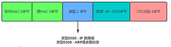
Receiver’s MAC Address: Globally unique, 6 bytes.
-
Sender’s MAC Address: Globally unique, 6 bytes.
-
Protocol Type: 2 bytes, most types are IP packets, which include TCP, UDP, and HTTP. Type 0800 = IP datagram, Type 0806 = ARP request and response.
-
Actual Data Layer: Generally 46-1500 bytes.
-
CRC Check: Cyclic Redundancy Check. This uses the XOR algorithm to determine whether errors occurred during the transmission of the entire packet.
-
It is important to note that the diagram above shows a containment relationship from top to bottom!
5.1 Main Functions of the Link Layer
5.1.1 Concurrency Resolution
The link layer primarily addresses how to resolve the order and data confusion issues that arise in the event of concurrency.
-
Dividing into multiple lanes. Each vehicle has one lane; in computer networks, this is called channel partitioning.
-
Odd-numbered travel today, even-numbered travel tomorrow, alternating. In computer networks, this is called turn-taking protocol.
-
No matter what, if there is something to do, head out first, and if it gets too congested, go back. Miss the peak and head out again. This is called random access protocol. The
famous Ethernetuses this method.
5.1.2 Robustness in Data Transmission
Who is this packet for? Who should receive it? What happens if there is an error in transmission? The solution is to use a physical address, called the link layer address, also commonly referred to as MAC address.
5.2 Link Layer Services
The most basic service of the data link layer is to reliably transmit data from the network layer of the source computer to the network layer of the target computer at the adjacent node. To achieve this, the data link layer must possess a series of corresponding functions:
-
Encapsulate data into frames; frames are the transmission units of the data link layer.
-
Control frame transmission, including handling transmission errors and adjusting the sending rate to match the receiver.
-
Manage the establishment, maintenance, and release of data link paths between two network entities.
These functions are specifically manifested in the following aspects.
5.3 Frame Encapsulation
To provide services to the network layer, the data link layer must use the services provided by the physical layer. The physical layer transmits data as a bitstream, so the data link layer uses a frame data block for effective error control. It adds headers and trailers to a segment of data, forming a frame. Upon receiving the bitstream from the physical layer, the receiver can identify the start and end of the frame based on the headers and trailers.
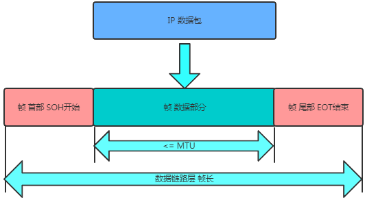
The advantage of using frame transmission is that when errors are detected in transmission, only the erroneous frame needs to be retransmitted, rather than retransmitting the entire stream of bits, greatly improving transmission efficiency.
Frame synchronization must solve the following issues:
-
How to identify the start and end of frames, which requires special frame headers and trailers for separation.
-
Identifying retransmitted data frames: when the receiving end receives a retransmitted data frame, it must be determined whether it is a new frame or a retransmitted frame. Various
frame synchronizationtechniques help make this distinction. Frame synchronization techniques allow the receiver to accurately distinguish the start and end of each frame from a bitstream that is not completely ordered and also identify retransmitted frames.
5.4 Transparent Transmission
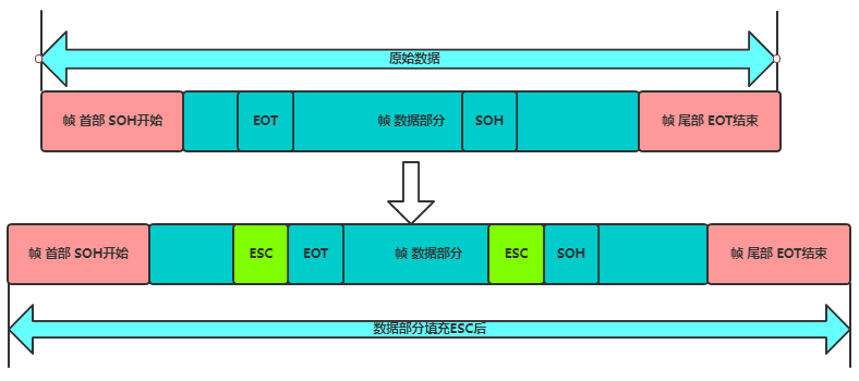
Since the start and end markers of frames use specially designated control characters, any 8-bit combination in the transmitted data must not match the bit encoding used for frame delimitation; otherwise, frame delimitation errors may occur.
If the frames being transmitted consist of text files entered from the keyboard, their data portions will not contain control characters like SOH or EOT. Thus, any characters typed from the keyboard can be transmitted in such frames, making this a transparent transmission.

The issue arises when the transmitted data is not keyboard input, such as binary code from a computer program or image. If EOT is encountered in the middle, it may lead to errors. The solution is to add an ESC escape character when the data portion encounters EOT or SOH.
5.5 Error Detection
Errors during the underlying data transmission can be broadly classified into two categories:
-
Bit errors: These occur when bits may change during transmission, meaning 1 may become 0 and vice versa.
-
Frame loss, duplication, or disorder: For example, if 123 is sent, the received packets might be 13, 1223, or 132 in such an order.
The metric for data transmission is the Bit Error Rate (BER): the ratio of erroneous bits to the total bits transmitted over a period of time.
Real communication links are not ideal; it is impossible to reduce the BER to zero. Therefore, to ensure reliable data transmission, various detection measures must be implemented. Currently, Cyclic Redundancy Check (CRC) detection technology is widely used in the data link layer.
6 The Story of Data Transmission
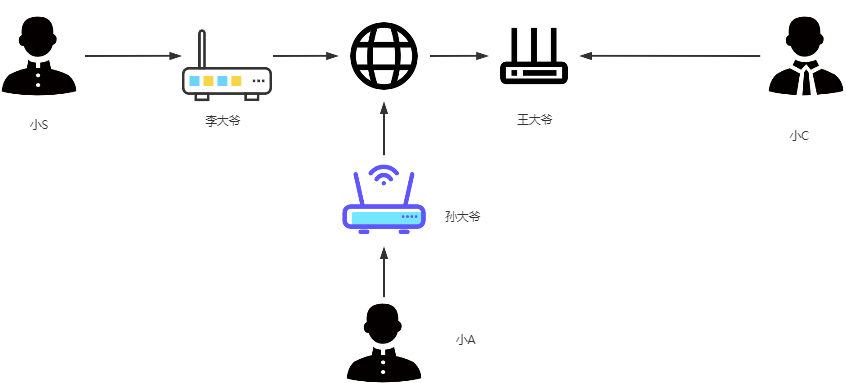
HTTP explanation + TCP explanation + this article’s IP explanation + link layer explanation = a packet’s journey diary. If purely technical articles feel too dull, let’s connect the knowledge points through a less rigorous life example:
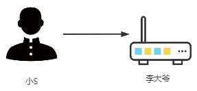
Your name is Little S, and you live in a neighborhood with many friends. When you want to play with your friends, you shout (hub), and everyone hears and comes down to play. Those who don’t want to play find the noise annoying, so they let Mr. Li in the reception room act as the switch. When you want to play with someone in the yard, you tell Mr. Li, and he informs you about the friend you’re looking for.
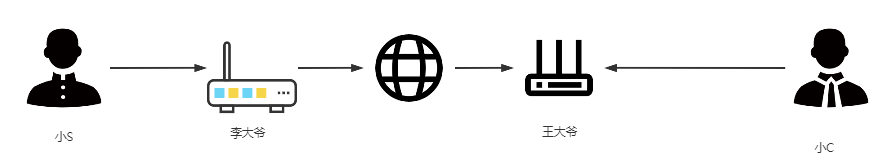
Later, you were grounded and not allowed to leave the neighborhood. At this point, when you want to communicate with the outside world, Little C, you send the information to Mr. Li. Mr. Li sees you want to communicate with the outside world. He instructs you to write the information in the standardized format (TCP/IP), but you find the address on the envelope is written as Little W, which cannot be delivered outside! You ask Little L for the real address, and Little L pulls out a name-address mapping book (DNS) to look up the real address of Little C, and then Mr. Li calls a courier responsible for delivering to this neighborhood (router). Here, it is important to note that the neighborhood only exposes a public address (public IP), but the neighborhood cannot have just one person! The neighborhood is divided into N rooms (private IP), and since N residents may switch rooms, every time they want to communicate with the outside, the courier router dynamically assigns a internal IP to you. Moreover, the router is clever enough to automatically assign different ports even if two residents use the same method (port) to send information, which is known as NAT technology.
Mr. Li, the courier, sends your information using SF/Yunda (modem) to convert the digital signals into pulse signals before sending it out. The information does not reach Little C’s neighborhood directly! Just like your parcel from Shenzhen sent to Beijing may pass through multiple transits, although your sender and receiver addresses are fixed, it may go through various routers and transits. This actually utilizes ARP packets and forwarding based on MAC addresses, providing routing functionality because the courier has a notebook (routing table) that records the next station address. Ultimately, the information will reach the reception room of Little C, where Mr. Wang is stationed, and he will send the information to Little C using the same method.

You have a friend, Little A, who lives in a neighborhood watched over by Mr. Sun. Since Little A’s yard has just been built, Mr. Sun just arrived, and he does not have Mr. Li’s and Mr. Wang’s phone numbers. Mr. Li and Mr. Wang also do not have Mr. Sun’s phone number. There are two scenarios:
-
The community aunt, Mrs. Zhao, informs Mr. Sun about Mr. Li and Mr. Wang’s addresses, while also telling Mr. Li and Mr. Wang about Mr. Sun’s address. This is called static routing.
-
Mrs. Zhao is ill, so Mr. Sun goes around spreading information, telling people that he is responsible for collecting and delivering messages for Little A’s yard, and this is overheard by Mr. Li and Mr. Wang, who then note it down in their contact lists (routing tables). Then Mr. Li and Mr. Wang send a message back to Mr. Sun, saying they are responsible for collecting and delivering messages for that yard. This is called dynamic routing.
One day, Little S wants to find Little A, so he tells Mr. Li his request, and Mr. Sun checks his contact list to find out that Mr. Sun is responsible for Little A’s yard. At this point, the goal is to find Mr. Sun, but there are two ways:
-
Mr. Li goes directly to find Mr. Sun.
-
Mr. Li asks Mr. Wang to find Mr. Sun.
Whether Mr. Li chooses 1 or 2 is called routing selection. Mr. Li would definitely choose 1 because he follows the principle of the least steps.
A few days ago, Little S had a quarrel with Little C. During this time, Little S has been calling Little A, and Little C wonders if Little S is speaking ill of him. So, Little C decides to eavesdrop on Little S and Little A’s conversation, but he cannot leave his yard. What should he do? Little C makes a decision: first, he tells Mr. Wang to call Mr. Li, saying, “You tell Mr. Li that Little A has moved to our yard, and from now on, I will handle all the calls for him.” Mr. Wang, confused, calls Mr. Li to say, “Now I am in charge of Little A, and Mr. Sun is no longer responsible.” As a result, Mr. Li updates his contact list, which is called routing deception.
From then on, whenever Little S tries to contact Little A, Mr. Li forwards it to Mr. Wang, who receives the information and pretends to be Little A communicating with Little S. Since Little C is guilty, fearing that Little S and Little A will meet and ask him directly, he also calls Little A in the name of Little S to reiterate the previous communication. This is called data eavesdropping.
Later, Little S continues to call Little A, and Little C thinks to himself, “Since you don’t call me, I will make sure you cannot reach Little A!”
-
Little C contacts a group of friends and conspires with them to send messages to Little A’s reception room at a fixed time every day. The moment the reception room’s Mr. Sun starts receiving, he will hear messages like “It’s thundering, bring in the clothes!”, “People are born from their mothers, demons are born from their mothers”, “What is your mother’s surname?” etc., making his head spin. He has to listen, but he cannot avoid it, and the phone keeps ringing!
Eventually, one day, Mr. Sun cannot take it anymore and yells, “I can’t stand it anymore!” and hangs himself!
This is the simplest DDOS attack, with Mr. Sun’s weak psychological resilience representing a bug in the data packet processing module, and Mr. Sun’s suicide representing router paralysis.
After a few days, a beautiful girl named Little B moves into Little C’s neighborhood, and he likes her very much, but Little B has a handsome boyfriend, leaving Little C helpless. Since Little B cannot leave her yard, the boyfriend must send messages to pursue her. Little C, eager to act, discovers that Mr. Wang can manage phone calls because he has a contact list. Since there may be two children named Little C in the same yard, names alone cannot differentiate them, so each line in the contact list has only two items:
Doorplate (MAC) Phone (IP) 1st Door 1234567 (Inside the 1st door is Little C) 2nd Door 7654321 (Inside the 2nd door is Little B)Every time a message is sent, the sender must state the phone number (IP) they are looking for, and Mr. Wang will check the contact list to knock on the door of the yard. For example, if someone says they are looking for 1234567, Mr. Wang will go to the 1st door to collect the information. If they are looking for 7654321, he will go to the 2nd door to collect the information. Here, the phone number represents the so-called IP address, and the doorplate represents the so-called MAC address. Each NIC has a unique MAC address, which is hardcoded by the manufacturer into the NIC’s chip.
Little C, in his quest to woo the girl, decides to tamper with Mr. Wang’s contact list. While Mr. Wang is in the restroom, Little C sneaks into the reception room and carefully alters Mr. Wang’s contact list. A few days later, when Little B’s boyfriend sends a message to Little B, he reports 7654321. Mr. Wang looks at the contact list:
Doorplate (MAC) Phone (IP) 1st Door 1234567 (This is Little C) 1st Door 7654321 (This has been altered to map to the 1st door)Mr. Wang is unaware of the change and goes to the 1st door to collect the information. Little C, posing as Little B’s father, sternly reprimands the boyfriend for his improper relationship with Little B and orders him to break up with her immediately. This behavior is known as ARP spoofing, as it is implemented in actual networks by sending ARP packets.
It is important to note that Mr. Wang now has two contact lists: one that records the phone numbers for each yard’s reception room, called the routing table, and another that records detailed information within the yard, called the ARP table. To ensure security, Mr. Wang can hide these tables, which corresponds to program encryption and decryption.
Mr. Wang’s employee handbook states that every month, the doorplate and phone number correspondence must be checked, which is the ARP table. This action is known as refreshing the ARP table, and the monthly time limit is referred to as the ARP table refresh cycle. Consequently, Little C must secretly alter that contact list every month to prevent the boyfriend from ever finding Little B, although this is also something he must do!
To add, Little C is very clever; if the contact list (ARP table) is altered to look like this:
Doorplate (MAC) Phone (IP) 1st Door 1234567 (This is Little C) 2nd Door 1234567 (Note: This has been altered, but he mistakenly changed it)The computer will pop up a dialog box indicating duplicate IP address, ultimately causing Mr. Wang to be at a loss, leading him to notify the 1st and 2nd doors that their phone numbers are duplicated. This way, Little B will realize someone is sabotaging her relationship, a phenomenon known as the scam being exposed.
Of course, to prevent his calls from being eavesdropped, Little S can also encrypt the content of the calls, which details were covered in the HTTP section.
5 References
-
On Gateways: https://zhuanlan.zhihu.com/p/35200000
-
TCP/IP Explanation: https://developer.51cto.com/art/201906/597961.htm
-
Little Lin’s Network: https://t.1yb.co/fQG3
Highly recommend a quality content sharing on architecture + algorithms. If you haven’t followed yet, please long press to follow:
Long press to subscribe for more exciting content ▼ If you find it helpful, please give it a thumbs up. Thank you sincerely.