Here is a collection of articles on the ARM series:
“Learning ARM from Scratch Collection“
0. Introduction
The UART is a very important module in an embedded system, serving as a bridge for interaction between the CPU and the user. User input to the program and CPU output to the terminal both rely on UART.
This article will explain the principles of UART and how to write a driver program based on the UART controller of Exynos4412.
1. What is UART
UART stands for Universal Asynchronous Receiver/Transmitter and is a key module for asynchronous communication between devices. UART handles the conversion between serial and parallel data streams and defines the frame format; as long as both communication parties use the same frame format and baud rate, communication can be completed with just two signal lines (Rx and Tx) without sharing a clock signal. Thus, it is also referred to as asynchronous serial communication. UART supports bidirectional communication and can achieve full-duplex transmission and reception. In embedded design, UART is used for communication between hosts and auxiliary devices, such as communication between car audio systems and external APs, as well as communication with PCs including monitoring debuggers and other devices like EEPROMs.
Typically, a suitable level shifter is needed, such as SP3232E or SP3485, and UART can also be used for RS-232, RS-485 communication, or connected to computer ports. UART is widely used in applications such as mobile phones, industrial control, and PCs.
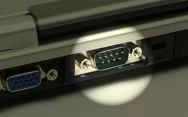
2. UART Communication Methods
UART uses asynchronous, serial communication.
Serial Communication
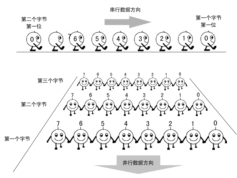
Serial communication refers to using a single transmission line to transmit data one bit at a time. It is like a line of people, with each data element arranged one after the other. As shown in the figure below, during transmission, data is sent serially bit by bit, with one bit transmitted per clock cycle. This method is relatively simple and slower, but requires fewer signal lines, typically one receive line and one transmit line to achieve serial communication.
The downside is that additional data must be added to control the start and end of a data frame. The advantage is that the communication lines are simple, allowing communication with simple cables, reducing costs, and making it suitable for long-distance communication, albeit at slower speeds.
Parallel Communication
Parallel communication is like a row of people moving forward together, transmitting simultaneously. This method transmits data proportional to the total bus width per clock cycle but is more complex to implement.
Asynchronous Communication
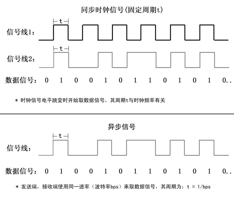
Asynchronous communication uses a character as the unit of transmission, and the time interval between two characters is not fixed, while the time interval between two adjacent bits within the same character is fixed.
In asynchronous communication technology, the data sender and receiver do not share a synchronized clock; they only have data signal lines, but the sender and receiver will sample data according to an agreed protocol (fixed frequency). The data sender sends data at a rate of 57600 bits per second, and the receiver also receives data at 57600 bits per second, ensuring the validity and correctness of the data. Typically, the baud rate is used to specify the transmission speed, measured in bps (bits per second).
Synchronous Communication
When sending data signals, a synchronous clock signal is sent simultaneously to synchronize the sampling frequency of the sender and receiver. As shown in the figure below, during synchronous communication, signal line 1 is a synchronous clock signal line that switches levels at a fixed frequency, with a frequency period of t. After each rising edge of the level, the data signal line 2 is sampled (high level represents 1, low level represents 0), and the output data information is obtained based on the sampled data levels. If both parties do not have a synchronous clock, the receiver will not know the sampling period and cannot correctly obtain the data information.
3. Frame Format
The data transmission rate is expressed by the baud rate, which is the number of binary bits transmitted per second. For example, if the data transmission rate is 120 characters per second, and each character is 10 bits (1 start bit, 7 data bits, 1 parity bit, 1 stop bit), the transmission baud rate would be 10 × 120 = 1200 characters per second = 1200 baud. The data communication format is shown in the figure below:
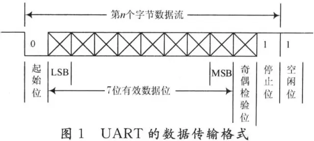
The meanings of each bit are as follows:
-
Start Bit: A logic “0” signal is sent first, indicating the start of character transmission. -
Data Bit: Can be 5 to 8 bits of logic “0” or “1”. For example, ASCII (7 bits), extended BCD code (8 bits). Little-endian transmission. -
Parity Bit: This bit, when added to the data bits, ensures that the number of “1” bits is even (even parity) or odd (odd parity). -
Stop Bit: This is a character data end marker. It can be 1 bit, 1.5 bits, or 2 bits of high level. -
Idle Bit: In a logic “1” state, it indicates that there is no data transmission on the current line.
Note: Asynchronous communication is character-based, and the receiving device can correctly receive data as long as it maintains synchronization with the sending device within the transmission time of one character after receiving the start signal.
The arrival of the next character’s start bit recalibrates synchronization (achieved by detecting the start bit for self-synchronization of the clocks of sender and receiver).
For standards like RS-232, RS-422, RS-485, readers can refer to the article “Understanding Serial Ports: UART, RS-232, RS-422, RS-485”.
4. Exynos4412 UART
This article discusses UART based on the Cortex-A9 architecture using Exynos4412 as an example.
1) Features
-
In Exynos4412, the UART has 4 independent channels, each of which can operate in interrupt mode or DMA mode, allowing UART to generate interrupts or DMA requests for data transmission between UART and CPU. Using the system clock, the UART baud rate of Exynos4412 can reach 4Mbps. Each UART channel contains two FIFOs for receiving and sending: -
Channel 0 has a 256-byte sending FIFO and a 256-byte receiving FIFO. -
Channels 1 and 4 have 64-byte sending FIFOs and 64-byte receiving FIFOs. -
Channels 2 and 3 have 16-byte sending FIFOs and 16-byte receiving FIFOs.
UART includes:
-
The baud rate can be programmed. -
Infrared receive/send. -
Each channel supports stop bits of 1 or 2. -
Data bits can be 5, 6, 7, or 8 bits.
Each UART also includes:
-
A baud rate generator, transmitter, receiver, and control logic.
2) UART Controller
Functional Modules
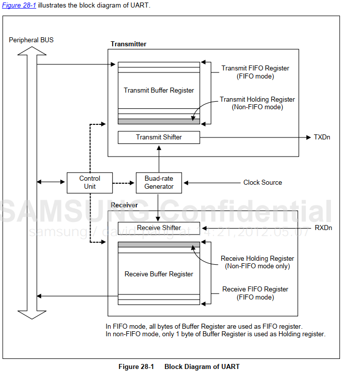
Each UART contains a baud rate generator, transmitter, receiver, and a control unit, as shown in the figure above:
-
Sending Data: The CPU first writes data into the sending FIFO, then the UART automatically copies the data from the FIFO to the “Transmit Shifter,” which sends the data bit by bit to the TxDn data line (inserting start bits, parity, and stop bits according to the set format). -
Receiving Data: The “Receive Shifter” receives data bit by bit from the RxDn data line and then copies it to the FIFO, from which the CPU can read the data.
UART implements communication asynchronously, with the sampling speed determined by the baud rate. The working frequency of the baud rate generator can be input from three clocks: PCLK (peripheral device frequency), FCLK/n (CPU working frequency division), UEXTCLK (external input clock). The baud rate setting register is programmable, allowing users to set the baud rate to determine the sending and receiving frequency.
The transmitter and receiver include a 64-byte FIFO and data shifter. UART communication is byte-stream oriented; after the data to be sent is written to the FIFO, it is copied to the data shifter (1-byte size), and the data is sent out through the sending data pin TXDn.
Similarly, received data comes in through the RXDn pin (1-byte size) to the receiving shifter, and then is copied to the FIFO receive buffer.
(1) Data Sending: The sending data frame is programmable, with a frame length specified by the user, including a start bit, 5-8 data bits, an optional parity bit, and 1-2 stop bits. The data frame format can be set through the ULCONn register. The transmitter can also generate a termination signal, which consists of a data frame of all zeros. After the current sending data is fully transmitted, the module sends a termination signal. After the termination signal is sent, it can continue to send data through the FIFO (FIFO) or the sending holding register (NON-FIFO).
(2) Data Receiving: Similarly, the receiving data is also programmable. The receiver can detect overflow errors, parity errors, frame errors, and termination conditions, with each error having a set error flag. • Overflow Error: New data overwrites old data before it can be read. • Parity Error: The receiver detects that the received data’s parity check fails, making the received data invalid. • Frame Error: The received data does not have a valid stop bit, making it impossible to determine the end of the data frame. • Termination Condition: RxDn maintains a logic 0 state for longer than the transmission time of a data frame.
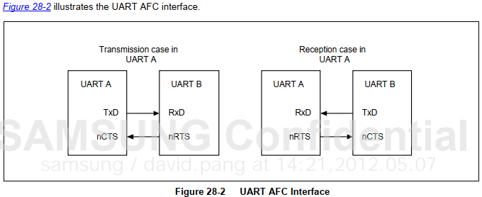
(3) Automatic Flow Control (AFC): UART0 and UART1 support automatic flow control with nRTS and nCTS. In the AFC case, both parties’ nRTS and nCTS pins are connected to each other’s nCTS and nRTS pins, controlling the sending and receiving of data frames through software. When AFC is enabled, the sender checks the nCTS signal status before sending data frames; when it receives the nCTS activation signal, it sends the data frame. The nCTS pin connects to the other party’s nRTS pin. The receiver, before preparing to receive data frames, must have more than 32 bytes of free space in its receiver FIFO; the nRTS pin will send an activation signal, and when its receiver FIFO has less than 32 bytes of free space, the nRTS must be set to inactive.
3) Selecting Clock Source
The clock sources for Exynos4412 UART have eight options: XXTI, XusbXTI, SCLK_HDMI24M, SCLK_USBPHY0, SCLK_HDMIPHY, SCLKMPLL_USER_T, SCLKEPLL, SCLKVPLL, controlled by the CLK_SRC_PERIL0 register.
After selecting the clock source, the division coefficients can also be set through DIVUART0 to 4, controlled by the CLK_DIV_PERIL0 register. The clock obtained from the divider is referred to as SCLK UART.
SCLK UART passes through the “UCLK Generator” shown in the figure above to obtain UCLK, whose frequency is the baud rate of the UART. The “UCLK Generator” is set through these two registers: UBRDIVn (UART BAUD RATE DIVISOR), UFRACVALn.
4) UART Configuration Registers
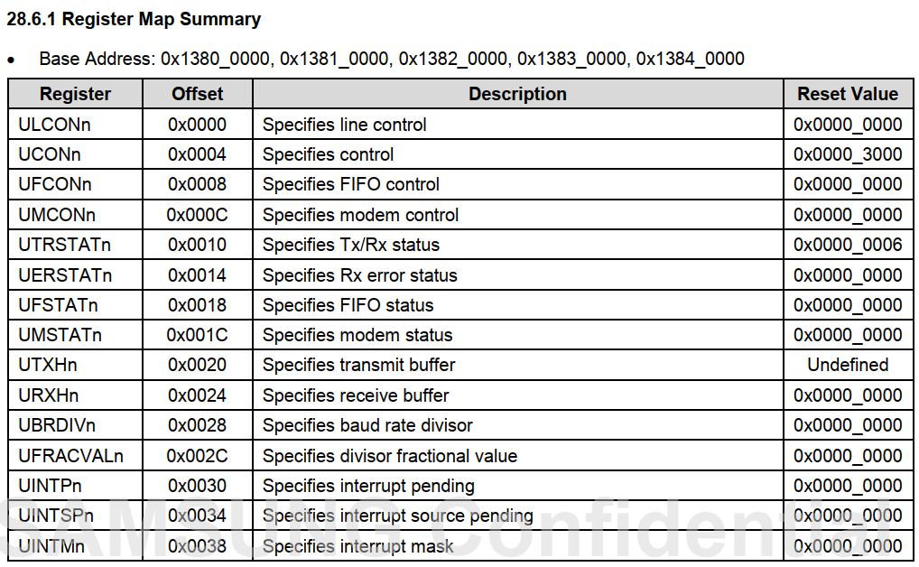
ULCONn
-
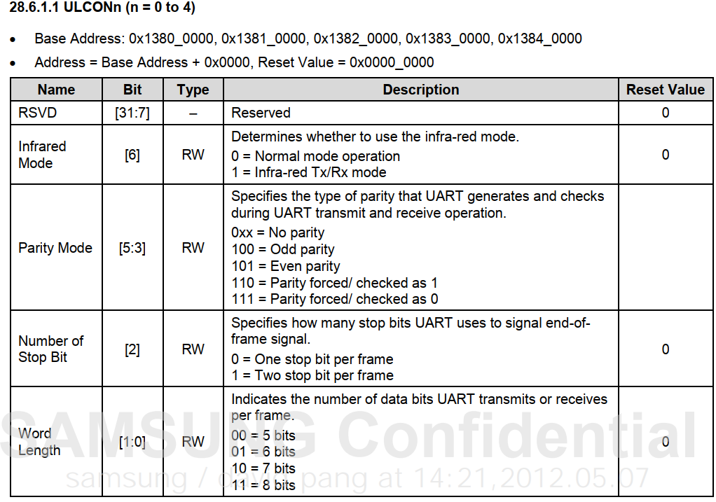
bit [6] Infrared Mode: Select whether UART0 uses infrared mode: 0 = normal communication mode, 1 = infrared communication mode.
-
bit [5:3] Parity Mode: Set the parity mode used by UART0 during data receiving and sending: 0xx = no parity, 100 = odd parity, 101 = even parity, 110 = forced parity/check for 1, 111 = forced parity/check for 0.
-
[2] Stop Bit: Set the number of stop bits for UART0: 0 = one stop bit per data frame, 1 = two stop bits per data frame.
-
[1:0] Data Bit: Set the number of data bits for UART0: 00 = 5 data bits, 01 = 6 data bits, 10 = 7 data bits, 11 = 8 data bits.
The common configuration for this register is:
ULCON2 = 0x3; //Normal mode, No parity, One stop bit, 8 data bits
UCONn
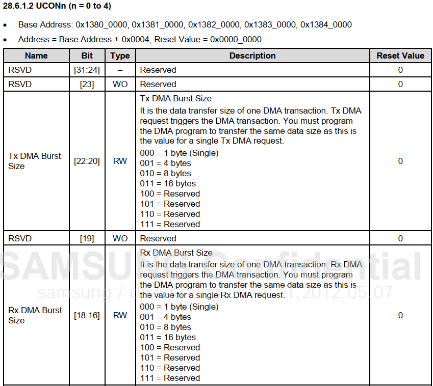
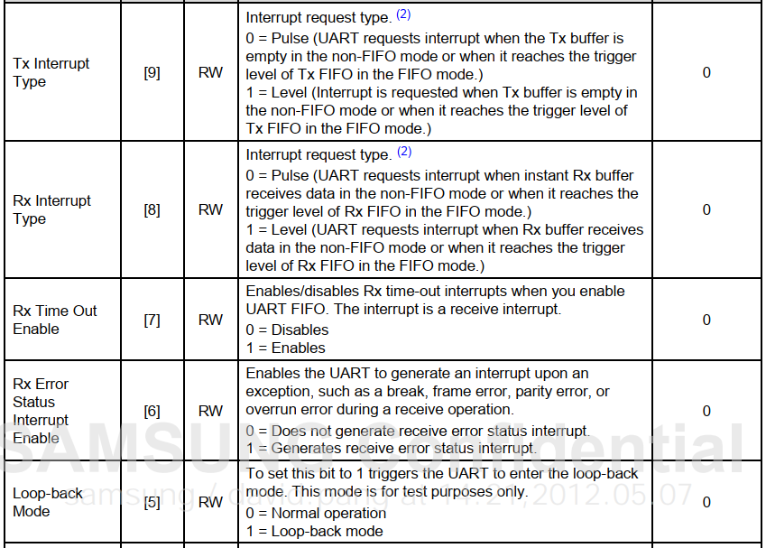
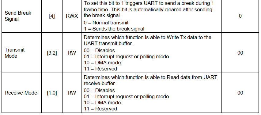
-
[15:12] FCLK Division Factor: When UART0 selects FCLK as the clock source, set its FCLK division factor. The working clock frequency of UART0 = FCLK / FCLK division factor + 6.
-
[11:10] UART Clock Source Selection: Choose the working clock for UART0: PCLK, UEXTCLK, FCLK/n: 00, 10 = PCLK, 01 = UEXTCLK, 11 = FCLK/n. When selecting FCLK/n as UART0’s working clock, other settings are required; please refer to the hardware manual.
-
[9] Data Sending Interrupt Generation Type: Set the UART0 interrupt request type. In non-FIFO transmission mode, an interrupt signal is generated immediately when the sending data buffer is empty. In FIFO transmission mode, an interrupt signal is generated immediately when the sending data trigger condition is met: 0 = pulse trigger, 1 = level trigger.
-
[8] Data Receiving Interrupt Generation Type: Set the UART0 interrupt request type. In non-FIFO transmission mode, an interrupt signal is generated immediately when data is received. In FIFO transmission mode, an interrupt signal is generated immediately when the receiving data trigger condition is met: 0 = pulse trigger, 1 = level trigger.
-
[7] Data Receiving Timeout: Set whether to generate a receiving interrupt if data times out: 0 = do not enable timeout interrupt, 1 = enable timeout interrupt.
-
[6] Data Receiving Error Interrupt: Set whether to generate a receiving status interrupt signal if an exception occurs during data reception, such as transmission abort, frame error, parity error: 0 = do not generate error status interrupt, 1 = generate error status interrupt.
-
[5] Loopback Mode: When this bit is set, UART enters loopback mode, which is only used for testing: 0 = normal mode, 1 = loopback mode.
-
[4] Send Termination Signal: When this bit is set, UART sends a termination signal of a frame length, and after sending, this bit automatically resets to 0: 0 = normal transmission, 1 = send termination signal.
-
[3:2] Sending Mode: Set which method to use to write data into the sending buffer: 00 = invalid, 01 = interrupt request or polling mode, 10 = DMA0 request.
-
[1:0] Receiving Mode: Set which method to use to write data into the receiving buffer: 00 = invalid, 01 = interrupt request or polling mode, 10 = DMA0 request.
The common configuration for this register is:
UCON2 = 0x5; //Interrupt request or polling mode
In general bare-metal cases, polling mode is used.
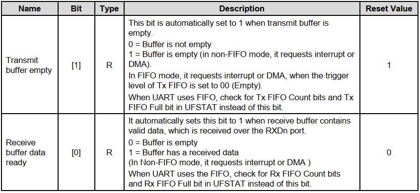
UTRSTATn
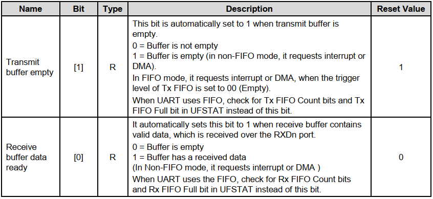
The UTRSTATn register indicates whether data has been sent completely and whether data has been received, as shown in the format below. The “buffer” mentioned above actually refers to the FIFO in the figure below; when not using FIFO functionality, it can be considered to have a depth of 1.
When we read data, we poll to check if bit[0] is set to 1, and then read data from the URXHn register; when we write data, we poll to check if bit[1] is set to 1, and then write data to the UTXHn register to send data.

UTXHn Register (UART Transmit Buffer Register)
CPU writes data into this register, and UART will save it into the buffer and automatically send it out.
URXHn Register (UART Receive Buffer Register)
When UART receives data, reading this register will give you the data.
UFRACVALn Calculate Baud Rate

Based on the given baud rate and the selected clock source frequency, the value of UBRDIVn register (n ranges from 0 to 4, corresponding to 5 UART channels) can be calculated using the following formula:
UBRDIVn = (int)( UART clock / ( baud rate x 16) ) – 1
The calculated UBRDIVn register value may not be an integer; the integer part is taken, and the fractional part is set by the UFRACVALn register. The introduction of the UFRACVALn register allows for more precise baud rate generation. “【Example】” When the UART clock is 100MHz and the desired baud rate is 115200 bps, then:
   100000000/(115200 x 16) – 1 = 54.25 – 1 = 53.25
       UBRDIVn = integer part = 53
       UFRACVALn/16 = fractional part = 0.25
       UFRACVALn = 4
5) Circuit Diagram
Peripheral circuit diagram:
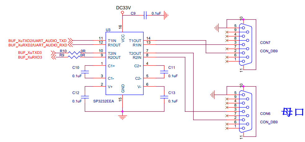
SP3232EEA is used to convert TTL levels to RS232 levels. We are using COM2.
Peripheral connection circuit diagram with the core board:

It can be seen that the UART’s send/receive pins are connected to GPA. Open the Exynos4412 chip manual:
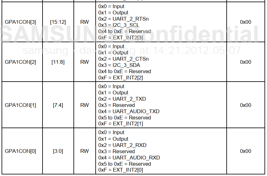
We only need to set the lower 8 bits of GPA1 to 0x22.
6. Example Code
This bare-metal code mainly implements the functions uart_init(), putc(), and getc().
uart_init()
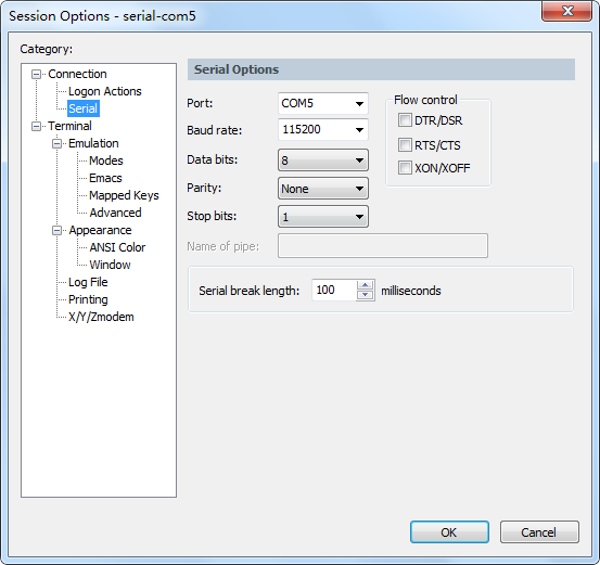
This function mainly configures the UART with a baud rate of 115200, data bits: 8, parity bit: 0, stop bits: 1, no flow control settings.
The following figure shows commonly used serial port tool configuration information running under Windows; the configuration information must be completely consistent.
putc()
This function sends a data byte to the serial port. Its implementation logic is to poll check the register UART2.UTRSTAT2, determining whether bit[1] is set to 1; if it is, the data to be sent can be stored in UART2.UTXH2.
getc()
This function receives a data byte from the serial port. Its implementation logic is to poll check the register UART2.UTRSTAT2, determining whether bit[0] is set to 1; if it is, it indicates that data is ready, and data can be taken from register UART2.URXH2.
Code
/*
 * UART2
 */
typedef struct {
    unsigned int ULCON2;
    unsigned int UCON2;
    unsigned int UFCON2;
    unsigned int UMCON2;
    unsigned int UTRSTAT2;
    unsigned int UERSTAT2;
    unsigned int UFSTAT2;
    unsigned int UMSTAT2;
    unsigned int UTXH2;
    unsigned int URXH2;
    unsigned int UBRDIV2;
    unsigned int UFRACVAL2;
    unsigned int UINTP2;
    unsigned int UINTSP2;
    unsigned int UINTM2;
} uart2;
#define UART2 (* (volatile uart2 *)0x13820000)
/* GPA1 */
typedef struct {
    unsigned int CON;
    unsigned int DAT;
    unsigned int PUD;
    unsigned int DRV;
    unsigned int CONPDN;
    unsigned int PUDPDN;
} gpa1;
#define GPA1 (* (volatile gpa1 *)0x11400020)
void uart_init()
{ /*UART2 initialize*/
 GPA1.CON = (GPA1.CON & ~0xFF ) | (0x22); //GPA1_0:RX;GPA1_1:TX
 UART2.ULCON2 = 0x3; //Normal mode, No parity,One stop bit,8 data bits
 UART2.UCON2 = 0x5;  //Interrupt request or polling mode
 //Baud-rate : src_clock:100Mhz
 UART2.UBRDIV2 = 0x35;
 UART2.UFRACVAL2 = 0x4;
}
void putc(const char data)
{ while(!(UART2.UTRSTAT2 & 0X2));
 UART2.UTXH2 = data;
 if (data == '\n')
   putc('\r');
}
char getc(void)
{ char data;
 while(!(UART2.UTRSTAT2 & 0x1));
 data = UART2.URXH2;
 if ((data == '\n')||(data == '\r'))
 {
   putc('\n');
   putc('\r');
 }else
   putc(data);
 return data;
}
puts/gets
void puts(const char *pstr)
{ while(*pstr != '\0')
  putc(*pstr++);
}
void gets(char *p)
{ char data;
 while((data = getc())!= '\r')
 {  if(data == '\b')
  {p--;
  }
  *p++ = data;
 }
 if(data == '\r')
 *p++ = '\n';
 *p = '\0';
}
7. How Bare-Metal Programs Can Support printf Function
First, let’s take a look at the directory structure of the files:
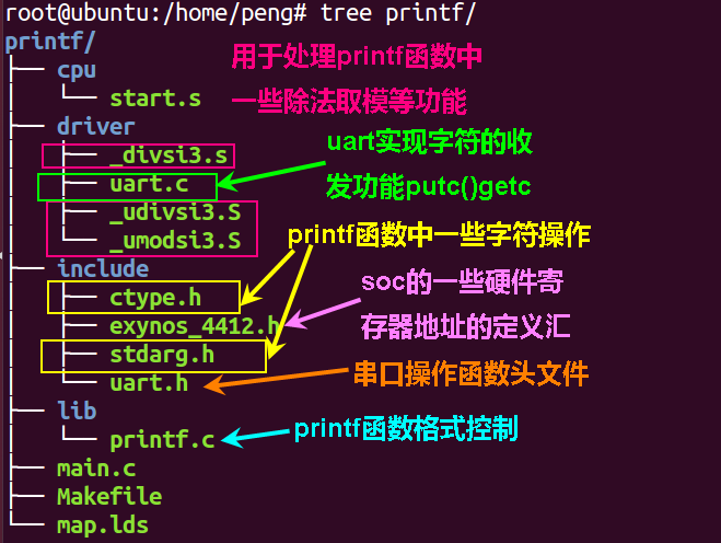
As usual, focus on the background and reply with “armprintf” to obtain the code.
Here we only show part of the file’s code.
“cpu/start.s” This file mainly implements the exception vector table and initializes the stacks for various modes.
.text
.global _start
_start:
  b  reset
  ldr  pc,_undefined_instruction
  ldr  pc,_software_interrupt
  ldr  pc,_prefetch_abort
  ldr  pc,_data_abort
  ldr  pc,_not_used
  ldr  pc,=irq_handler
  ldr  pc,_fiq

_undefined_instruction: .word  _undefined_instruction
_software_interrupt: .word  _software_interrupt
_prefetch_abort:  .word  _prefetch_abort
_data_abort:   .word  _data_abort
_not_used:    .word  _not_used
_irq:     .word  irq_handler
_fiq:     .word  _fiq

reset:

 ldr r0,=0x40008000
 mcr p15,0,r0,c12,c0,0  @ Coprocessor instruction sets the exception vector table address

init_stack:
  ldr  r0,stacktop         /*get stack top pointer*/

 /********svc mode stack********/
  mov  sp,r0
  sub  r0,#128*4          /*512 byte  for irq mode of stack*/
 /****irq mode stack**/
  msr  cpsr,#0xd2
  mov  sp,r0
  sub  r0,#128*4          /*512 byte  for irq mode of stack*/
 /***fiq mode stack***/
  msr  cpsr,#0xd1
  mov  sp,r0
  sub  r0,#0
 /***abort mode stack***/
  msr  cpsr,#0xd7
  mov  sp,r0
  sub  r0,#0
 /***undefine mode stack***/
  msr  cpsr,#0xdb
  mov  sp,r0
  sub  r0,#0
   /*** sys mode and usr mode stack ***/
  msr  cpsr,#0x10
  mov  sp,r0             /*1024 byte  for user mode of stack*/

  b  main @ Jump to the main function in C

 .align 4

 /****  swi_interrupt handler  ****/

 /****  irq_handler  ****/
irq_handler:

 sub  lr,lr,#4
 stmfd sp!,{r0-r12,lr}
 .weak do_irq   @ This function may not be defined
 bl do_irq  @ Jump to interrupt entry
 ldmfd sp!,{r0-r12,pc}^

stacktop:    .word   stack+4*512 @ Define stack top
.data

stack:  .space  4*512  @ Allocate a block of stack space
“lib/printf.c”
This file mainly implements the printf function with some format controls and string conversions that require the use of some macros from ctype.h and stdarg.h. The specific implementation of vsprintf will not be detailed here; interested readers can research it themselves.
……
void printf (const char *fmt, ...)
{
 va_list args;
 unsigned int i;
 char printbuffer[100];
 va_start (args, fmt);

 /* For this to work, printbuffer must be larger than
  * anything we ever want to print.
  */
 i = vsprintf (printbuffer, fmt, args);// Format the input parameters
 va_end (args);
 puts (printbuffer); // Call the puts function we encapsulated in the previous chapter to print the string to the serial port
}
“main.c” This file can directly call the printf() function to print information.
void  delay_ms(unsigned int num)
{
    int i,j;
    for(i=num; i>0;i--)
 for(j=1000;j>0;j--)
  ;
}
/*
 *  Bare-metal code, unlike LINUX application layer, must include loop control
 */

int main (void)
{
 int i = 0;
 while (1) {
  printf("aaaaaaaaaaaaa\n");
  delay_ms(500);
 }
   return 0;
}
“Makefile”
CROSS_COMPILE = arm-none-eabi-
NAME =gcd
CFLAGS=-mfloat-abi=softfp -mfpu=vfpv3 -mabi=apcs-gnu -fno-builtin  -fno-builtin-function -g -O0 -c  -I ./include -I ./lib
LD = $(CROSS_COMPILE)ld
CC = $(CROSS_COMPILE)gcc
OBJCOPY = $(CROSS_COMPILE)objcopy
OBJDUMP = $(CROSS_COMPILE)objdump
OBJS=./cpu/start.o ./driver/uart.o  \
        ./driver/_udivsi3.o ./driver/_divsi3.o ./driver/_umodsi3.o main.o ./lib/printf.o
#=============================================================================#
all:  $(OBJS)
 $(LD)  $(OBJS) -T map.lds -o $(NAME).elf
 $(OBJCOPY)  -O binary  $(NAME).elf $(NAME).bin
 $(OBJDUMP) -D $(NAME).elf > $(NAME).dis
%.o: %.S
 $(CC) $(CFLAGS) -c -o  $@ $<
%.o: %.s
 $(CC) $(CFLAGS) -c -o  $@ $<
%.o: %.c
 $(CC) $(CFLAGS) -c -o  $@ $<
clean:
 rm -rf $(OBJS) *.elf *.bin *.dis *.o
Makefile and map.lds refer to “Starting from Scratch with ARM-GNU Pseudo Instructions, Code Compilation, and lds Usage”.
In the future, we will use this template to write driver codes for other hardware.
Recommended Reading

To join the group, please add a contact on WeChat, and I will guide you through embedded systems.