The Raspberry Pi, as a microcomputer with powerful functions and an affordable price, is favored by developers, makers, and enthusiasts. It can be used in various fields such as website building, smart home control, game development, and programming skill learning.
Aili Light Technology has launched the Raspberry Pi 5 GMSL Camera Access Kit to meet the demand for GMSL camera integration with the Raspberry Pi development board, providing multi-channel GMSL camera access capabilities. This article aims to introduce the application scenarios, hardware, and software usage methods of the Aili Light GMSL Camera Access Kit, helping you smoothly complete the installation and configuration, thus starting your innovative development journey.
Application Scenarios
The Aili Light Technology Raspberry Pi 5 GMSL Camera Access Kit provides three combination configuration schemes, allowing you to choose the appropriate configuration according to your project development needs. The core product of the kit is Aili Light Technology’s self-developed adapter board, which achieves the physical connection between the GMSL camera and the Raspberry Pi 5 development board through the adapter board.
|
Model |
Contents List |
|
AKT-R48A-000 |
Adapter board*1, FPC cable*2 |
|
AKT-R48A-200 |
Adapter board*1, FPC cable*2, 8MP camera*2, Fakra cable*2 |
|
AKT-R48A-400 |
Adapter board*1, FPC cable*2, 3MP camera*4, Fakra cable*4 |
For more product information, please follow the Aili Light Technology official website: www.aili-light.com
The adapter board is currently compatible with two GMSL cameras from Aili Light Technology, namely: ISX031 series 3M (1920*1536) 30fps camera and OX08B series 8M (3840*2160) 30fps camera, and provides driver support.

The GMSL Camera Access Kit meets the following typical application scenarios:
1
Master Application


Connection Diagram
2
Slave Application

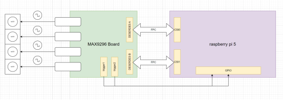
Connection Diagram
Hardware Connection Guide
1. Power Connection
Connect the power adapter of the adapter board and the power adapter of the Raspberry Pi 5 development board.
2. CSI Interface Connection
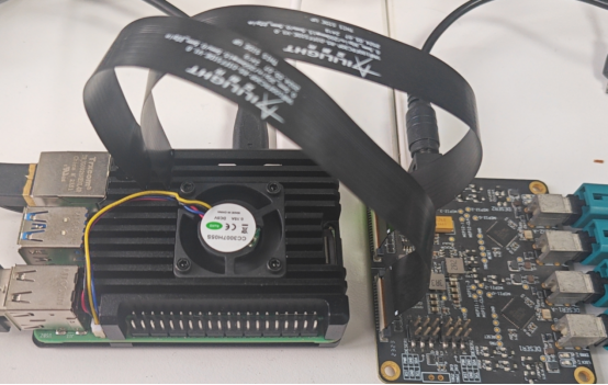
The Raspberry Pi 5 development board’s CSI interface supports 2 channels of 4Lane MiPi signal input. Through the custom FPC cable from Aili Light, the connection between the adapter board and the development board can be achieved, as shown in the diagram below:
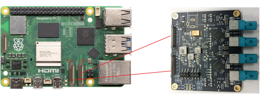
Note: The CSI0 and CSI1 marked in the figure are software-defined information and are related to software parameters. Please refer to the indicated method in the diagram for connection. If connected in other ways, the software may not run normally.
3. RST and PWR Pin Connection
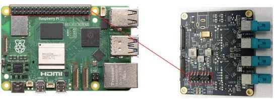
The adapter board is equipped with RST (reset) and PWR (power control) pins, where the RST pin is used for camera reset, while the PWR pin is responsible for camera power management. To achieve repeated configuration and restart of the camera by software within a single power-on cycle, just connect these two pins to the 40-pin interface of the Raspberry Pi 5 development board to control the camera.
4. External Trigger Connection
The adapter board is equipped with RST (reset) and PWR (power control) pins, where the RST pin is used for camera reset, while the PWR pin is responsible for camera power management. To achieve repeated configuration and restart of the camera by software within a single power-on cycle, just connect these two pins to the 40-pin interface of the Raspberry Pi 5 development board to control the camera.
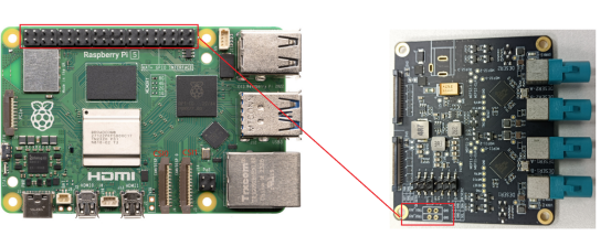
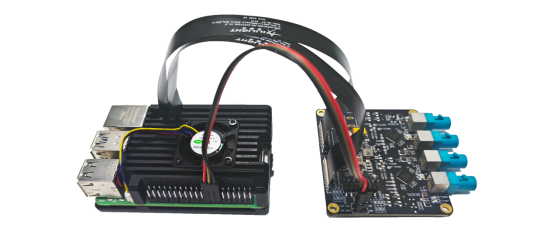
Software Configuration Guide
1. Driver Loading
The driver loading consists of two parts: the loading of the device tree and the loading of the Driver.
1.1 Loading the Device Tree
① Place the DTBO file in the corresponding path
The Raspberry Pi supports a mature Overlays mechanism, namely DTBO (Device Tree Overlay), used to patch the device tree, which is not greatly related to specific kernels. As long as there are no major changes in the device tree (such as node name changes), the independently compiled DTBO file is usually universal.Therefore, we only need to copy max9296\bin\6.6.31+rpt-rpi-2712\dtbo\max9296.dtbo, to the /boot/firmware/overlays/ directory of the Raspberry Pi.
Reference command:
sudo cp /mnt/nas_share/raspi_image/overlays/max9296.dtbo /boot/firmware/overlays/② Execute loading DTBO to the device tree
Here, we need to add support for max9296.dtbo in the config.txt file, reference command:
sudo vim /boot/firmware/config.txtdtoverlay=max9296,sensor-type=ISX031_MAX96717_2CHdtoverlay=max9296,cam0,sensor-type=ISX031_MAX96717_2CH[all]#dtoverlay=max9296,sensor-type=0X08B MAX96717 1CH#dtoverlay=max9296,cam0,sensor-type=0X08B MAX96717 1CHdtoverlay=max9296,sensor-type=ISX031 MAX96717 2CHdtoverlay=max9296,cam0,sensor-type=ISX031 MAX96717 2CH#dtoverlay=max9296,sensor-type=ISX031 MAX96717 1CH#dtoverlay=max9296,cam0,sensor-type=ISX031 MAX96717 1CH#dtoverlay=max9296,sensor-type=ISX031 MAX96717 2CH#dtoverlay=max9296,cam0,sensor-type=0X08B MAX96717 1CHcd /proc/device-tree/axi/pcie@120000/rp1/i2c@80000/max9296@10
Based on the official image version released by Raspberry, we compile the corresponding driver program for each version and store it on GitHub for everyone to use. You only need to place the .ko file corresponding to the kernel version in the /lib/modules/{kernel version}/ directory.
$ uname -r6.6.31+rpt-rpi-2712sudo depmodFinally, input the following command:
sudo modprobe max9296When the driver is successfully loaded, the dmesg command will output the corresponding log information. If no error reports appear in the log content, it indicates that the driver has been successfully loaded.
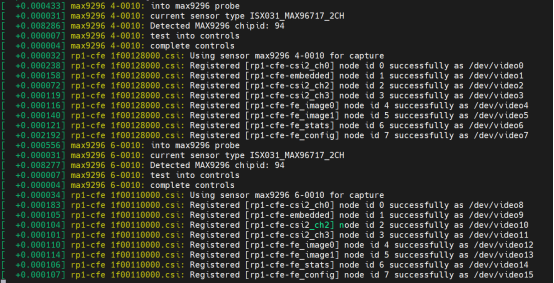
Note: In this scenario, we choose to use the modprobe method instead of the insmod method to load the driver. The core reason is that the v4l2 driver framework under Linux is relatively complex and highly dependent on multiple modules. Using the modprobe method can automatically load and manage these dependent driver modules, ensuring that the v4l2 driver can be loaded and run correctly and completely.
./aili_run_camera.sh csi_channel width height deserdes_channelParameter Analysis:
-
csi_channel: Indicates the specified CSI (Camera Serial Interface) channel to be used. All configurable parameters are as follows:
csi0 — Use csi0, refer to the hardware connection diagram
csi1 — Use csi1, refer to the hardware connection diagram
all — Use both csi0 and csi1 simultaneously
-
width: Indicates the current width of the resolution of the sensor connected to this CSI channel.
-
height: Indicates the current height of the resolution of the sensor connected to this CSI channel.
-
deserdes_channel: Used to specify whether to use one or two deserdes channels. When only one channel is used, LINKA must be used, with the following configuration parameters:
1ch — Use one channel of deserdes, LINKA
2ch — Use two channels of deserdes
Notes:
-
The width and height must match the loaded sensor driver. Specifically, when loading the ISX031_MAX96717_2CH or ISX031_MAX96717_1CH driver, width should be set to 1920, and height should be set to 1536. When loading the OX08B_MAX96717_1CH driver, width should be set to 3840, and height should be set to 2160.
-
When loading the OX08B_MAX96717_1CH driver, deserdes_channel can only be configured as 1ch (single channel). Example usage:
./aili_run_camera.sh all 1920 1536 2ch //Indicates using csi0 and csi1 simultaneously, with the resolution set to 1920×1536, and the two channels of deserdes output simultaneously, that is, collecting 4 images simultaneously.
After execution, if the console displays the executed command without errors, it indicates that the operation has been successfully completed.
3. Using GStreamer to Display Images
You can use the script located in the max9296\script\ path to display images simultaneously. Please copy the aili_review_camera.sh script file to any location on the Raspberry Pi and execute the following command to start the image display function.
./aili_review_camera.sh csi_channel width height deserdes_channelParameter Analysis:
-
csi_channel: Indicates the specified CSI (Camera Serial Interface) channel to be used. All configurable parameters are as follows:
csi0 — Use csi0, refer to the hardware connection diagram
csi1 — Use csi1, refer to the hardware connection diagram
all — Use both csi0 and csi1 simultaneously
-
width: Indicates the current width of the resolution of the sensor connected to this CSI channel.
-
height: Indicates the current height of the resolution of the sensor connected to this CSI channel.
-
deserdes_channel: Used to specify whether to use one or two deserdes channels. When only one channel is used, LINKA must be used, with the following configuration parameters:
1ch — Use one channel of deserdes, LINKA
2ch — Use two channels of deserdes
Notes:
-
Ensure that the parameters of this script are consistent with those of the ./aili_run_camera.sh script. -
This command must be executed on a local console with a graphical user interface and cannot be executed through remote SSH connection.
Application Examples
“
Example One:
4 Channels of 3M (1920*1536) Camera Application
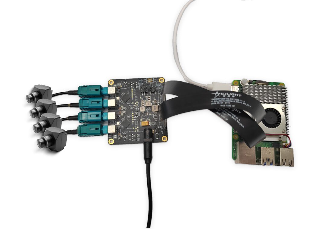
➯ Using 4 Aili Light ISX031 series cameras
config.txt configuration:
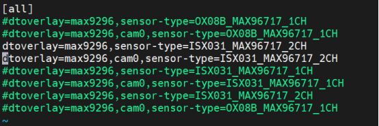
Execute commands in sequence:
./aili_run_camera.sh all 1920 1536 2ch./aili_review_camera.sh all 1920 1536 2chExecution Result:

“
Example Two:
2 Channels of 8M (3840*2160) Camera Application
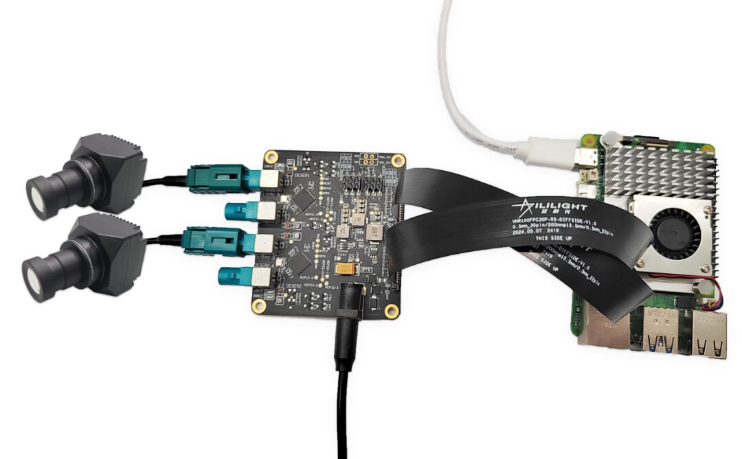
➯ Using 2 Aili Light OX08B series cameras
config.txt configuration:
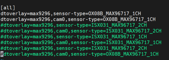
Execute commands in sequence:
./aili_run_camera.sh all 3840 2160 1ch./aili_review_camera.sh all 3840 2165 2chExecution Result:

“
Example Three:
3 Channel Camera Application
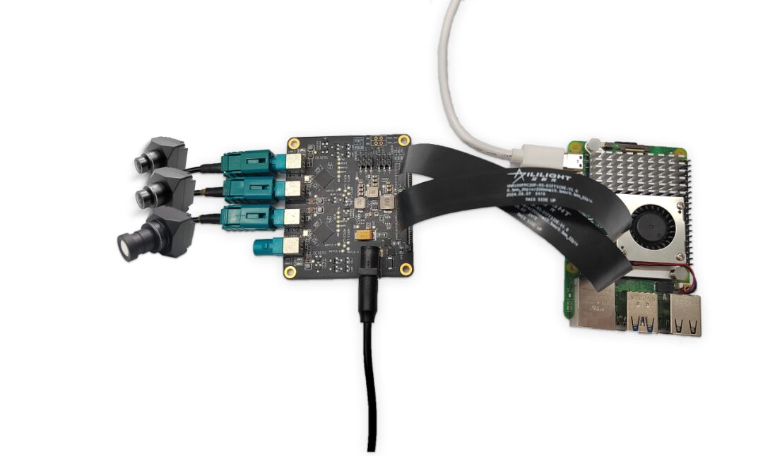
➯ Using 2 Aili Light ISX031 series 3M (1920*1536) cameras and 1 Aili Light OX08B series 8M (3840*2160) camera
config.txt configuration:
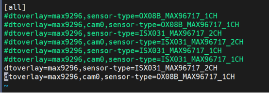
Execute commands in sequence:
./aili_run_camera.sh csi1 1920 1536 2ch./aili_run_camera.sh csi0 3840 2160 1ch./aili_review_camera.sh csi1 1920 1536 2ch./aili_review_camera.sh csi0 3840 2160 1chExecution Result:

More exciting content
Click to follow
「Aili Light Technology」
↓ ↓ ↓

Aili Light Technology creates the Raspberry Pi 5 GMSL camera access kit
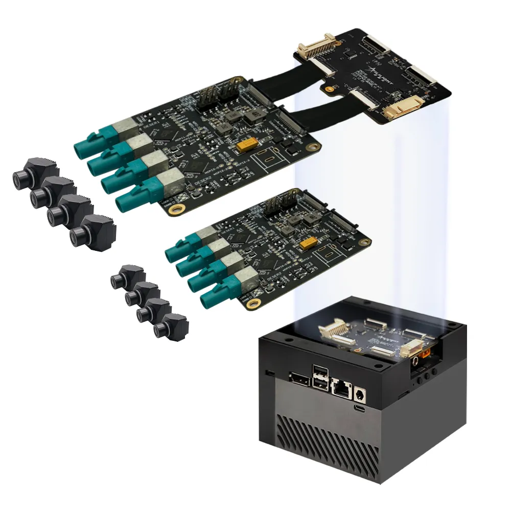
Aili Light launches GMSL camera access kit compatible with Jetson Orin