Module Introduction
Module Name: DT-06 Wireless
Module Function: The module achieves real-time transparent transmission of data between the module’s serial port and WiFi.
Module physical images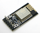
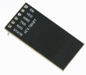
Module Features
The TTL-WiFi module is developed based on the ESP-M2 WiFi module, with TTL, EN, STATE, and other pins exposed. The product has built-in serial transparent transmission firmware that can achieve real-time data transmission from the device’s TTL port to WiFi/cloud, featuring low power control, status indication, and other functions.
The module can directly replace the existing wired serial port, enabling data collection and control for embedded devices.
-
Built-in industrial-grade transparent transmission firmware V3.0, reliable and stable, with WEB interface configuration;
-
Based on the high-performance ESP-M2 WiFi module, overall dimensions: 34mm×17mm×4mm;
-
Supply voltage: 4.5V~6.0V, TTL voltage: 3.3V (compatible with 5.0V);
-
Exposed pins: STATE, TXD, RXD, EN;
-
Average current: 80mA; 170mA when WiFi data is being sent; 20μA in deep sleep mode;
-
Supports serial AT commands;
-
Supports reprogramming and OTA firmware upgrades;
-
Real-time seamless transmission of serial and WiFi data;
-
Built-in HTTP Web Server, supports web configuration of various parameters;
-
WiFi supports AP, STA, and AP+STA modes;
-
Supports automatic reconnection in STA mode and TCP Client mode;
-
Serial port supports setting baud rate, data bits, parity, stop bits, and packet time;
-
Supports baud rates (bps): 300/600/1200/2400/4800/9600/19200/38400/57600/74800/115200/230400/460800/921600/1843200/3686400;
-
Supports AP enable, custom SSID/password, custom IP and subnet, etc.;
-
Automatically scans surrounding hotspots, supports STA enable, DHCP, custom IP and subnet, etc.
-
Supports TCP Server, TCP Client, UDP Server, UDP Client, and UDP local area network broadcasting;
-
Remote server address supports DNS domain name automatic resolution;
-
Supports checking status via AT commands;
-
IO4 pin indicates WiFi status.
-
Operating temperature range: -40℃-125℃;
-
Application scenarios: smart home, wireless data collection and transmission, smart car control, wireless serial printer, outdoor LED lights, industrial control, etc.
Module Structure Diagram
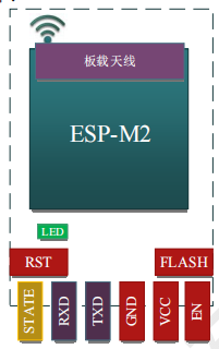
Interface Definition
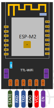
The interface definition is shown in the figure below
Product button and LED functions
-
LED is connected to VCC3.3 through a pull-up resistor, the other end connects to the module’s GPIO4 pin
-
SW1 connects to the GPIO0 pin of the WiFi module. Together with the SW2 button, it completes firmware downloading
-
SW2 connects to the module’s RST pin. Together with SW1, it completes firmware downloading
LED Indicator
-
Always on
The WiFi module is in STA or STA+AP mode and has successfully connected to the wireless router
-
Slow flashing
IO pin level changes once every second; the WiFi module has not successfully connected to the wireless router; the WiFi module is in AP mode; the WiFi module is in STA mode and is attempting to connect to the wireless router; the WiFi module is in AP+STA mode and is attempting to connect to the wireless router;
-
Fast flashing
When the SW1/Flash button is pressed; when data is received at the serial port, or data is forwarded from the network to the serial port, the LED will flash quickly;
-
Always off
The WiFi module is not working, possibly due to abnormal power supply or non-transparent transmission firmware
Pin Definition
-
STATE
GPIO4; built-in transparent transmission firmware, indicates network connection status: in STA mode, connected to the wireless router, STATE outputs low level;
-
RXD
GPIO3; the module has a 22Ω current-limiting resistor in series, can connect to external 5.0V level; can be used as UART Rx when flashing the Flash;
-
TXD
GPIO1; the module has a 22Ω current-limiting resistor in series, can connect to external 5.0V level; can be used as UART Tx when flashing the Flash
-
GND
GND
-
VCC
Module power supply: 4.5V~6.0V, recommended to use 5.0V
-
EN
Chip enable pin, high level: valid, chip operates normally; low level: chip is off.
Software Transparent Transmission WEB Configuration
The product has a built-in HTTP Server, which can be configured through a PC or other smart terminal’s browser, without the need for other configuration tools or apps.
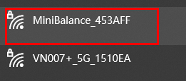
In the factory settings, the firmware defaults to work in AP mode, and the hotspot name actively emitted by the WiFi module is: “Minibalance_XXXXXX”, where “xxxxxx” is the last six digits of the module’s MAC address. You can connect to this hotspot using a PC with a wireless card or a smartphone/tablet (supporting Android, iOS, Windows Phone, etc.). Hotspot password: 12345678.
Find Minibalance_XXXXXX in the WiFi devices on the computer
Enter the password, and after successfully connecting, enter the product’s default IP address: 192.168.4.1 in the browser

On the status page, the module’s MAC address, IP address in STA mode, WiFi connection status, IP address in AP mode, system running time, and other information are displayed.
Among them: the values displayed for WiFi Status include: idle, connection, wrong password, no AP found, connect failed, connected. If the STA connection is successful, the current connection signal strength will be displayed.
system running time displays the device’s power-on running time
Serial Port Configuration
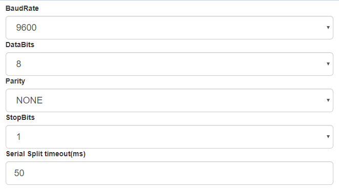
In the serial port settings page, you can set the baud rate, data bits, parity bits, stop bits, etc., and also set the serial port’s packet time interval.
Configurable serial port baud rates: 300//600/1200/2400/4800/9600/19200/38400/57600/74800/115200/230400/460800/921600/1843200/3686400
Data bits: 5/6/7/8
Parity bits: NONE, ODD, EVEN
Stop bits: 1, 1.5, 2
After completing the settings, use the SAVE button to save the settings.
WiFi Configuration
The WiFi module can be set to work in AP, STA, or AP+STA modes
AP: emits a signal for other devices to connect
STA: acts as a client, connecting to external WiFi signals
AP settings:
-
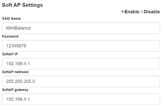
AP mode can be turned on or off
-
Custom SSID name and password for the AP. If the password is left blank, it means no encryption; otherwise, WEP encryption is used.
-
Custom IP address, subnet mask, gateway address, etc., for the WiFi module in AP mode
Networks (Network Configuration)
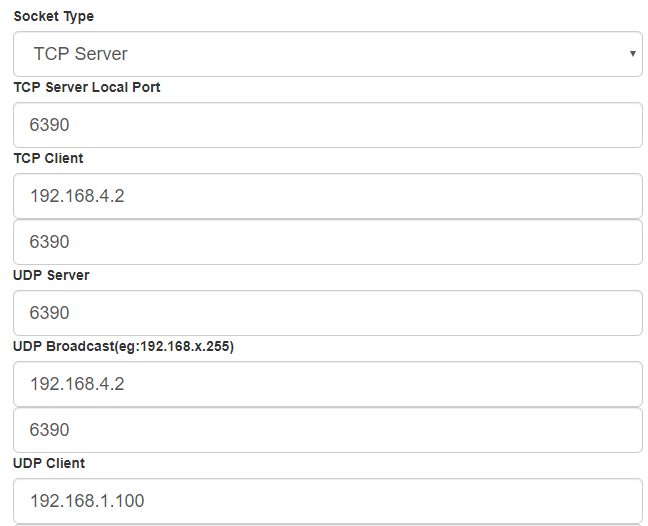
In the network configuration interface, you can set the network working mode of the WiFi module. The selectable working modes include: TCP server/client, UDP server/client, UDP broadcasting, etc.
-
When selecting TCP/UDP Client, the remote server’s IP address supports dynamic domain names, and the firmware will automatically obtain the IP address based on the domain name
-
UDP broadcasting mode supports broadcasting within the local area network, the filling rule is: 192.168.x.255, where x is the module’s IP address segment number obtained in STA mode.
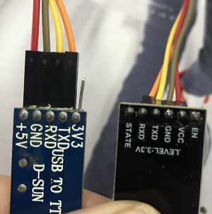
Minimum System for Module Use
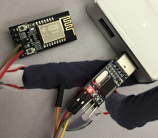
The module only requires a 5.0V DC power supply to operate. The module’s RXD connects to the TXD of the USB to TTL module, and the module’s TXD connects to the RXD of the USB to TTL module.
Install the corresponding APP software on the phone; the iOS version has issues with connecting and disconnecting, which may be related to the version or the phone. Try using an Android phone, and open the serial port debugging assistant on the computer
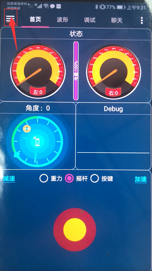
First, click this area to connect to WiFi

Dragging this area will display information in the serial port debugging assistant

When dragging upwards, it will print A; if you keep dragging, it will continuously print A, and releasing will print Z. Similarly, dragging in other directions will print E, G, C
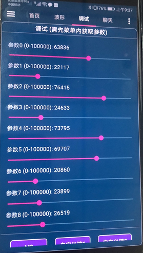
Switch to the debugging interface, drag the horizontal bar, and drag the parameter to 20545

Serial port debugging assistant displays
Source: GuYueJu
Friendly Reminder:
Due to recent changes in the WeChat public platform’s push rules, many readers have reported not seeing updated articles in a timely manner. According to the latest rules, it is recommended to frequently click “Recommended Reading, Share, Collect,” etc., to become a regular reader.
Recommended Reading:
-
Game not running? Russian self-developed CPU performance test backfires!
-
Will we use 7G networks in 2058? Are the details in “The Wandering Earth 2” reasonable?
-
Breaking Europe’s monopoly, BYD customizes two dual-fuel transport ships
-
Microsoft lays off 10,000, triggering a snowball effect in American tech companies, with hundreds of thousands laid off last year!
-
Exposed Xiaomi car extreme cold testing, Lei Jun personally involved!
Please click 【View】 to give the editor a thumbs up
