1. System Objectives and Definitions
-
Objective: To achieve centerless interconnection and bidirectional wireless communication among multiple individual terminals without relying on external public base stations (4G/5G) or a central node.
-
Method: Utilize antennas + RF modules (AD936X) + baseband modules (FPGA modulation) to establish a physical layer communication link, completing basic packet transmission and status synchronization.
-
Features:
-
Centerless, multi-hop self-organizing network (AdHoc)
-
Fully hardware implementation (can be expanded to multi-node Mesh)
-
Lightweight, low power consumption, quick deployment
2. System Architecture Diagram
The wireless communication between three nodes is shown in the diagram below (Figure 1).
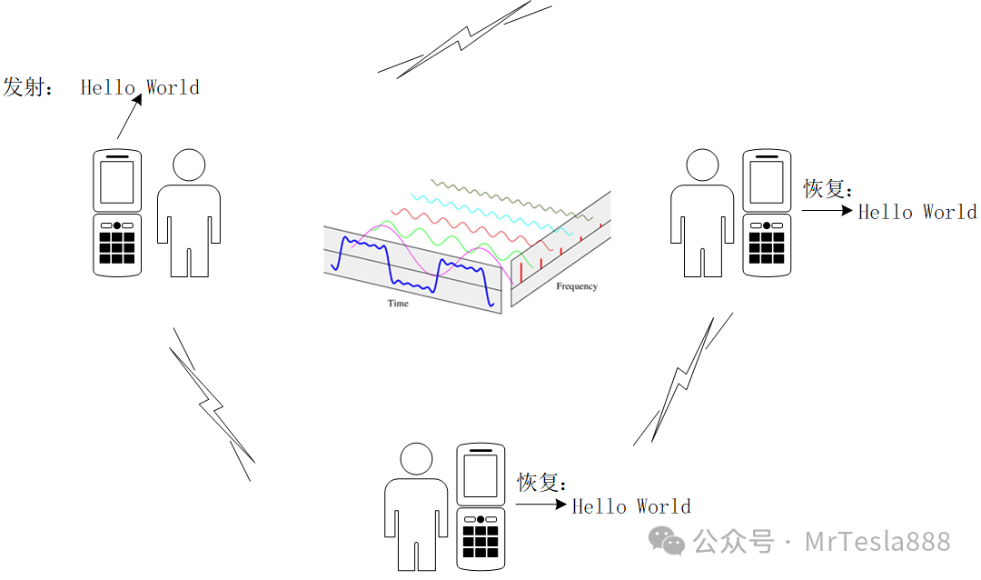
Figure 1: Individual soldier self-organizing network communication schematic
3. Communication Technical Parameters
The self-organizing network communication parameters are shown in the table below (Table 1).
Table 1: Communication Parameter Table
|
Name |
Parameter Value Description |
|
Communication Mode |
TDD bidirectional time-division communication |
|
Modulation Method |
BPSK/QPSK/64QAM (can be expanded to OFDM) |
|
Bandwidth Setting |
1~32 MHz (configurable by AD936X) |
|
Frequency |
600MHz/1.4GHz or custom (supports 70 MHz~6 GHz) |
|
Data Rate |
500 kbps~80 Mbps |
|
Receiving Sensitivity |
Better than –100 dBm (depends on modulation method) |
|
Scrambling and Encryption |
Can addM sequence scrambling + simple XOR encryption |
4. Communication Process (Simplified Design)
The time slot rotation TDD for self-organizing network communication is shown in the table below (Table 2), with time synchronization achieved through fixed periods/predefined training symbols.
Table 2: Communication Process Table
|
Time Slot |
Individual Soldier A Operation |
Individual Soldier B Operation |
|
T0 |
Transmit data frame |
Receive mode |
|
T1 |
Receive acknowledgment frame |
Send acknowledgment frame |
|
T2 |
Wait for the next frame |
Wait for the next frame |
5. Communication Protocol Frame Structure (Simplified Version)
The communication protocol frame structure for wireless self-organizing networks is shown in the table below (Table 3).
| Table 3: Communication Protocol Frame Structure |
|
[Header] |
[Frame Header] |
[Address] |
[Data Field] |
[CRC] |
[Frame Tail] |
|
4B |
2B |
1B |
32B |
2B |
1B |
-
Header: Used for synchronization capture at the receiving end
-
Frame Header: Distinguishes data/control/ACK types
-
Address: Supports extended multi-node
-
Data Field: Up to32B (expandable)
-
CRC: Cyclic Redundancy Check
-
Frame Tail: Indicates end of frame
6. Baseband Minimum Module Design
The functional description of the baseband minimum module design is shown in the table below (Table 4).
| Table 4: Communication Protocol Frame Structure |
|
Module Name |
Functional Description |
|
AD9361 SPI Configuration |
Initialize AD9361 registers, set frequency, bandwidth, etc. |
|
Baseband Modulation |
Implement BPSK/QPSK/64QAM modulation, pulse shaping filtering; Modulate data into IQ symbols (BPSK/QPSK/64QAM), output to AD9361 |
|
Receive Demodulation |
Receive IQ data from AD9361, perform matched filtering and symbol decision |
|
Packetization and Depacketization |
Package data → Add start/stop bits/verification/CRC; Add frame header, frame tail, CRC, etc. structure for reliable communication |
|
TDD State Machine |
Control transmit/receive switching, ensure communication polling rhythm synchronization |
|
UART Module |
Interact with user terminal, output received data and display status |
7. RF Unit Configuration (Typical Parameters)
The functional configuration of the minimum RF front-end module design is shown in the table below (Table 5).
|
Name |
Parameter Configuration |
|
Center Frequency |
600MHz/1.4GHz or custom (supports 70 MHz~6 GHz) |
|
Bandwidth |
32 MHz |
|
Analog Gain Mode |
Automatic gain/fixed gain (fixed during testing) |
|
TDD Control Interface |
GPIO control, TDD synchronization window adjustable |
|
Receive/Transmit Mode |
Utilize TDD synchronization control, using timing or GPIO trigger |
|
Gain Control |
Fixed gain or automatic gain mode (AGC) |
|
Calibration |
Use initialization scripts provided by ADI for calibration |