In embedded development, you must have encountered various buses, including address and data buses within the chip, high-speed and low-speed buses, as well as various communication buses outside the chip. However, it seems that people still do not have a good grasp of buses, so today I have selected an article about buses for everyone to read.
If a single-log bridge can only accommodate one person at a time, and people on both ends want to cross, to avoid congestion and blockage, we must take effective measures. For example, we can stipulate that at certain times, people from one end can cross while those from the other end wait until their turn arrives. We can also specify that when there are many people, they should cross in the order of arrival or by age. In this way, we inadvertently experience the most primitive idea of modern electronic information data being transmitted through a bus using a time-division multiplexing system.
The development of modern network information, especially regarding cost and space, has made bus transmission a hot topic, replacing point-to-point transmission. Its emergence provides the greatest convenience and the most effective technical solution for information transmission. If a microprocessor and its components and peripheral devices were connected by point-to-point lines for communication, all the connections would become intricate and even difficult to implement.
A series of activities closely related to our lives are all involved with the application of bus technology, such as accessing the internet, making phone calls to relatives and friends, and using USB drives to store information. Although the forms of popular buses differ, their main principles are essentially time-division systems, frequency-division systems, phase-division systems, and code-division systems.
As the saying goes, “When soldiers come, generals block; when water comes, earth drowns.” Faced with the variety of buses, we can only start from the basic principles and understand their essence deeply, rather than being confused by their diverse appearances, to skillfully master and flexibly apply the various bus technologies currently in use or that will be used.
A bus, referred to in English as “BUS”, is akin to the Chinese term “公共车” (public bus). This is a very vivid analogy; the route of a public bus is fixed, and anyone can take the bus to any stop along that route. If we compare people to electronic signals, this is the true meaning behind calling it “BUS” instead of “CAR”.
Of course, from a professional standpoint, a bus is a structural form that describes the transmission lines of electronic signals; it is a collection of signal lines and a common channel for transmitting information between subsystems. Through the bus, information can be transmitted, exchanged, shared, and logically controlled among all components within the system. In a computer system, it serves as the public channel for transmitting information between the CPU, memory, input, and output devices, with various components connected through the host and external devices connected to the bus through corresponding interface circuits.
Buses can be classified in many ways, such as external and internal buses, system buses and non-system buses, etc. Below are several of the most commonly used classification methods.
1. Classification by Function
The most common classification of data buses is based on functionality, which can be divided into address bus, data bus, and control bus. In some systems, the data bus and address bus can be shared under the control of an address latch, which is called multiplexing.
The address bus is specifically used for transmitting addresses. In the design process, the most frequently seen should be selecting the storage address of external memory from the CPU address bus. The bit width of the address bus often determines the size of the storage space; for example, if the address bus is 16 bits, the maximum storage space is 2^16 (64KB).
The data bus is used for transmitting data information and can be classified into unidirectional and bidirectional data buses; bidirectional data buses usually adopt a tri-state form. The bit width of the data bus typically matches the word length of the microprocessor. For instance, the Intel 8086 microprocessor has a word length of 16 bits, and its data bus width is also 16 bits. In actual work, the data transmitted over the data bus is not necessarily complete data.
The control bus is used for transmitting control signals and timing signals. For example, when a microprocessor operates on external memory, it must first send read/write signals, chip select signals, and interrupt response signals through the control bus. The control bus is generally bidirectional, with the transmission direction determined by the specific control signal, and its bit width also depends on the actual control needs of the system.
2. Classification by Transmission Method
Buses can be classified into serial buses and parallel buses based on the data transmission method. From a theoretical perspective, parallel transmission is actually superior to serial transmission, but it comes with increased costs. In simple terms, parallel transmission is like a multi-lane highway, while serial transmission only allows one car to pass through a single-lane road.
Common serial buses include SPI, I2C, USB, IEEE1394, RS232, CAN, etc.; parallel buses are relatively fewer, with common examples being IEEE1284, ISA, PCI, etc.
3. Classification by Clock Signal Method
Buses can be divided into synchronous buses and asynchronous buses based on whether the clock signal is independent.
A synchronous bus has a clock signal independent of the data, meaning a separate line is used as the clock signal line; while an asynchronous bus extracts the clock signal from the data, typically using the edges of the data signal as the clock synchronization signal.
Basic Principles of Bus Transmission
Based on the previous definition of a bus, we know that the basic function of a bus is to transmit signals. To ensure that information from each subsystem can be effectively and timely transmitted, and to avoid mutual interference between signals and excessive physical crowding, the best approach is to adopt multiplexing technology. Thus, the basic principle of bus transmission is multiplexing technology.
Multiplexing refers to a mechanism where multiple users share a common channel. Currently, the most common types include time-division multiplexing, frequency-division multiplexing, and code-division multiplexing.
1. Time-Division Multiplexing (TDMA)
Time-division multiplexing divides the channel into multiple time slots, where signals from different sources request responses in different time slots, ensuring that their transmission times do not overlap on the time axis.
2. Frequency-Division Multiplexing (FDMA)
Frequency-division multiplexing divides the available frequency band of the channel into several non-overlapping frequency bands, with each signal occupying one of these bands after frequency modulation, allowing multiple signals of different frequencies to be transmitted over the same channel. When the receiving end receives the signal, it will use appropriate band-pass filters and frequency demodulators to restore the original signal.
3. Code-Division Multiplexing (CDMA)
In code-division multiplexing, the transmitted signals each have their specific identification codes or address codes. The receiving end will distinguish the transmission information on the common channel based on these codes, and only when the identification code or address code matches will the transmission information be received.
Communication Protocols of Buses
Understanding the communication protocols of buses is a key step in the learning process. All materials introducing bus technology devote a significant amount of space to describing their protocols, especially the seven-layer definitions of ISO/OSI.
In fact, to understand a bus protocol, the main thing is to comprehend the characteristics and meanings represented by each bit of the frame data. The effective sending and receiving of data between bus nodes is achieved through the judgment and confirmation of frame data bits or segments by each node.
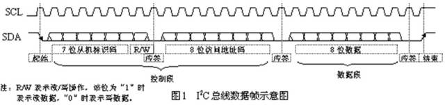
As shown in Figure 1, the data frame for transmitting one byte of data on the common I2C bus consists of a dual-wire serial bus formed by the data line SDA and the clock line SCL. Any circuit module connected to the bus can act as both a transmitter (master) and a receiver (slave). The frame data includes control codes (including slave identification codes and access address codes), data codes, as well as start signals, end signals, and acknowledgment signals.
Start Signal: When SCL is high, SDA transitions from high to low to start data transmission.
Control Code: Used to select the target and object of the operation, i.e., to activate the circuit that needs to be controlled, determining the type of object being controlled. During reading, when the SCL clock line is at a high pulse, the data bits on SDA will not change.
Data Code: This is the specific useful data (such as contrast, brightness, etc.) and information sent from the master to the slave. During reading, the data bits on SDA will not change.
Acknowledgment Signal: After the receiver receives the 8-bit data, it sends a specific low level back to the sender. The direction of read/write is exactly opposite to that of other data bits, meaning the slave sends out the low level, and the master reads this low level.
End Signal: When SCL is high, SDA transitions from low to high to indicate the end of the data frame transmission.
Of course, different buses will have different definitions for their data bits or segments, but based on the same principles, one can quickly understand the characteristics and features of their protocols. Although the sizes of their information frames may vary, specific data bits or segments will be defined according to the requirements of their protocols, similar to what is mentioned regarding the I2C bus.
Main Technical Indicators
The main technical indicators for evaluating a bus include its bandwidth (i.e., transmission rate), data bit width (bit width), operating frequency, and the reliability and stability of the transmitted data.
1. Bandwidth (Transmission Rate), Bit Width, and Operating Frequency
Bandwidth refers to the amount of data transmitted on the bus per unit time, i.e., the maximum data transmission rate in MB per second.
Bit Width refers to the number of binary data bits that can be transmitted simultaneously on the bus, or the width of the data bus, such as 32 bits, 64 bits, etc.; the wider the bus bit width, the greater the data transmission rate, and the wider the bus bandwidth.
The operating clock frequency of the bus is measured in MHz and is related to the transmission medium, the amplitude of the signals, and the transmission distance. Under the same hardware conditions, the frequency of differential signal transmission is often much higher than that of single-ended signals, because the amplitude of differential signals is only half that of single-ended signals.
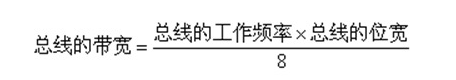
The bandwidth, bit width, and operating frequency of the bus are closely related, and their relationships are as follows:
2. Reliability of Data Transmission
Reliability is the most critical parameter for evaluating a bus; without reliability, the transmitted data is erroneous, which negates the practical significance of the bus. To improve the reliability of the bus, the following measures are typically adopted:
-
1) Before sending data frames, the sender listens to the bus, and only when it detects that the bus is idle can it send data frames, thus avoiding data conflicts between different nodes.
-
2) Using twisted pair differential signals to transmit data reduces the voltage swing of a single wire, minimizing the high-frequency harmonics generated by signal edges.
-
3) Allowing the edges of data to have a certain slope.
-
4) Adding matching resistors and capacitors to reduce signal emission on the bus and balance the distributed capacitance on the bus.
-
5) Adopting appropriate network topologies and shielding techniques to minimize interference from other signals.
Additionally, software measures such as digital filtering, data verification, and error correction are used to enhance the reliability of data transmission.
Learning is a gradual process, and understanding bus technology is also an ongoing process that evolves with technological advancements. As the saying goes, “To do a good job, one must first sharpen one’s tools.” Only by starting from the most basic principles and building a solid foundation can one integrate knowledge in future studies, advancing further into this knowledge point and broadening their knowledge base.
Source|Internet
Reprinted from|Embedded ARM
The copyright belongs to the original author. If there is any infringement, please contact us for deletion.
END


关于安芯教育


安芯教育是聚焦AIoT(人工智能+物联网)的创新教育平台,提供从中小学到高等院校的贯通式AIoT教育解决方案。
安芯教育依托Arm技术,开发了ASC(Arm智能互联)课程及人才培养体系。已广泛应用于高等院校产学研合作及中小学STEM教育,致力于为学校和企业培养适应时代需求的智能互联领域人才。