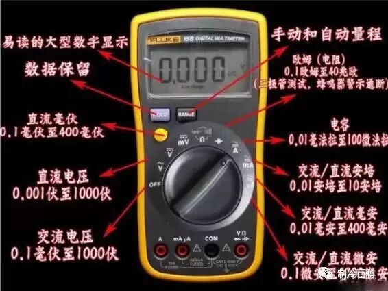
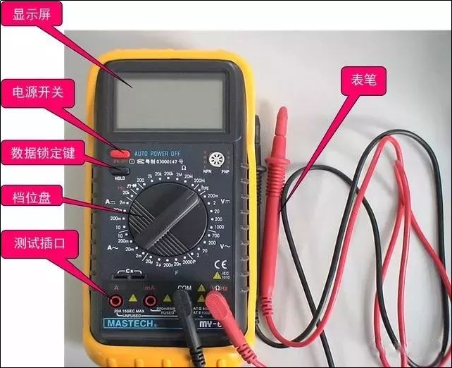
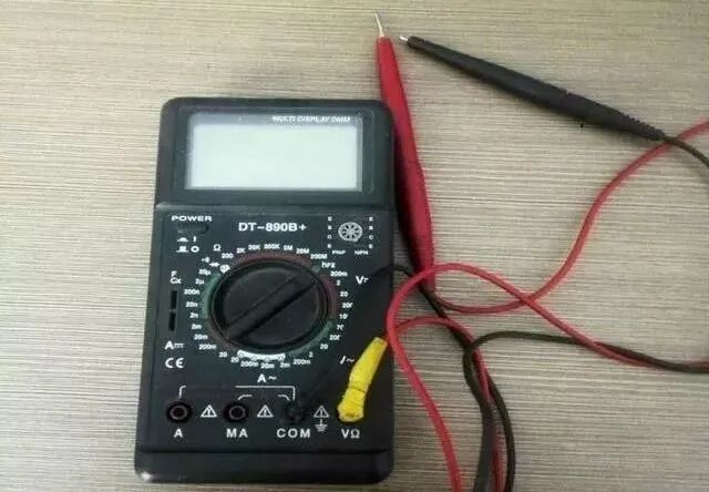
 Correctly using a multimeter not only allows for quick identification of faults but also prevents damage to electrical devices and the multimeter itself. Below are some tips for using a multimeter.Before measuring, check the range; do not measure without checking the range. After measuring, switch to the empty range. The dial should be level, and the reading must be aligned. The range must be appropriate, and the reading must be accurate. Measure resistance (R) when the circuit is not powered, discharge capacitors before measuring capacitance (C), and zero the meter before switching ranges. Remember that the black lead is negative, and when measuring current (I), it should be in series, while measuring voltage (U) should be in parallel. Develop a habit of using one hand.Multimeters can generally be divided into analog multimeters and digital multimeters.
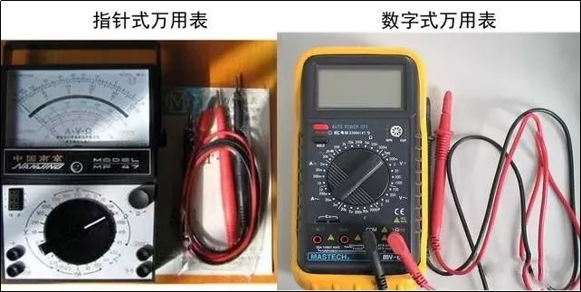
Analog Multimeter:
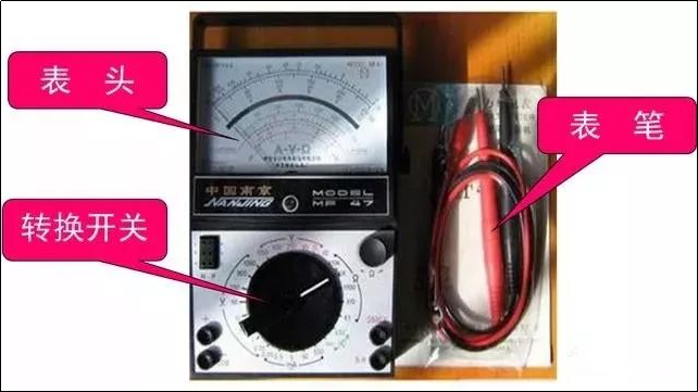
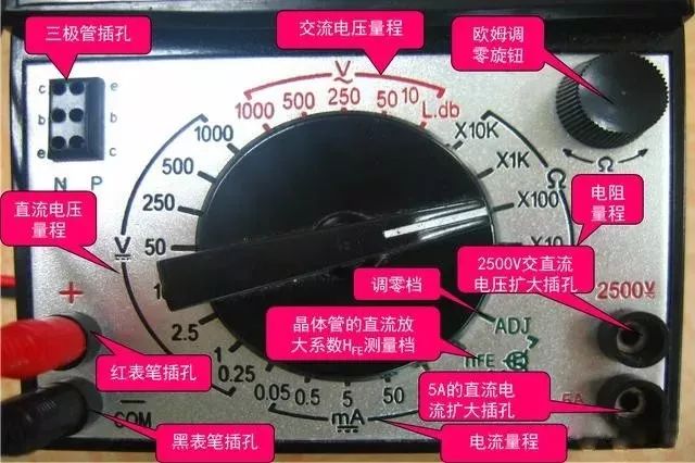
The structure of an analog multimeter: There are many types of analog multimeters, but their basic structure is similar. The main components of an analog multimeter include the meter head, the selector switch (also known as the range switch), and the measurement circuit.Meter Head: This is the display device for measurements; the meter head is essentially a sensitive ammeter.Selector Switch: This selects the type and range (or multiplier) of the measured quantity.Measurement Circuit: This converts different types and magnitudes of measured quantities into a direct current that the meter head can accept.Meter Head: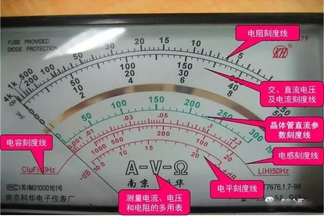 Selector Switch:
 Digital Multimeter:
 Dial:
Dial:
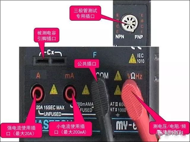
Ports:
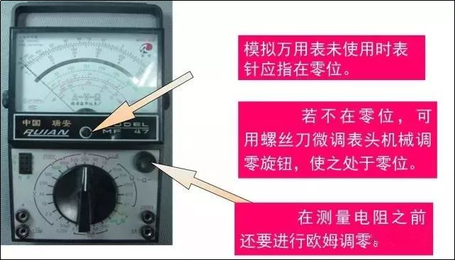
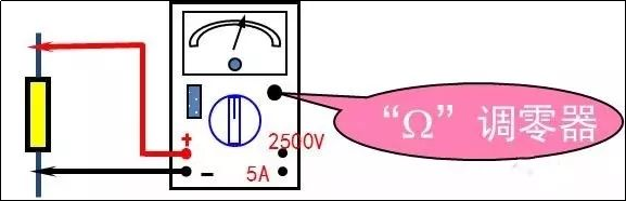
Using the Multimeter—Zero Adjustment
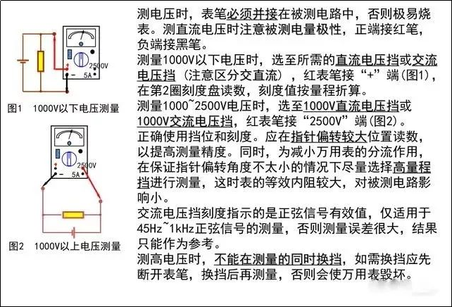
Correct Wiring:The red probe should connect to the “+” polarity socket, and the black probe should connect to the “—” or “*” or “COM” polarity socket.When measuring DC quantities, pay attention to the positive and negative polarities to avoid reversing the pointer.When measuring current, the meter should be in series with the circuit being measured; when measuring voltage, the meter should be in parallel across the circuit.When measuring transistors, remember that the red probe connects to the negative terminal of the internal battery, and the black probe connects to the positive terminal of the internal battery.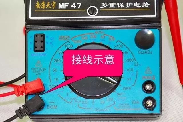 Correctly Selecting Measurement Ranges:When measuring voltage, set the selector switch to the corresponding voltage range; when measuring current, set it to the corresponding current range, etc.When selecting current or voltage ranges, it is best to have the pointer positioned above two-thirds of the scale; when selecting resistance ranges, it is best to have the pointer positioned in the middle of the scale.When measuring, if the range of the measured value is uncertain, first set the selector switch to the maximum range, then gradually reduce it to an appropriate range based on the pointer’s deflection.Common Measurement Methods—AC and DC Voltage Measurement
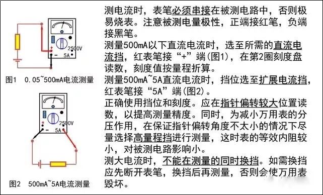
Current Measurement:
Resistance Measurement:Select the range and zero adjustment: When measuring resistance, first select the appropriate resistance range, then short the probes and adjust the “Ω” zero adjuster to make the pointer return to 0 (zero adjustment should be done again for each range change).Measurement and Reading: Connect the probes across the resistor and take the reading. The resistance value is the reading on the resistance scale multiplied by the current selected resistance range multiplier.Range: Choose a range that keeps the pointer between one-third and two-thirds of the full scale to minimize measurement error.Probe Polarity: The battery in the multimeter is active when measuring resistance, with the battery “+” connected to the panel “-”. When using the multimeter’s resistance range to determine the polarity of diodes or rectifying components, be mindful of probe polarity; current flows from the black probe, through the external component, and returns through the red probe.Measuring Resistance in a Circuit: The circuit must be powered off for measurement. If it is uncertain whether there are parallel resistors present, the resistor must first be disconnected from the circuit; if there are capacitors in the circuit, they should be discharged before measurement.Checking Electrolytic Capacitor Leakage Resistance: Set the switch to R×1K range, the red probe must connect to the negative terminal of the capacitor, and the black probe connects to the positive terminal of the capacitor.
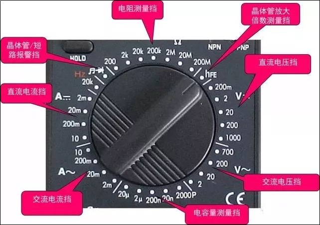
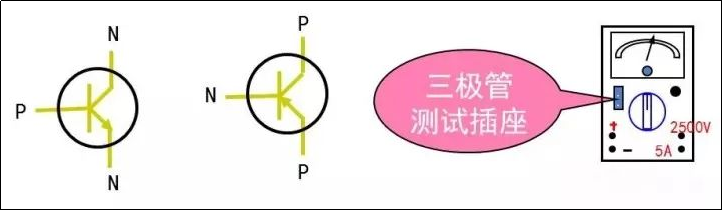
Measuring the DC Current Gain (hFE) of a Transistor:Select the ADJ range, short the probes, and adjust the ohm zero adjuster so that the pointer points to 300hFE.Select the hFE range, and insert the leads of the transistor being tested into the corresponding E, B, C sockets of the transistor tester; the deflection of the pointer indicates the approximate DC current gain of the transistor.Insert N-type transistors into the NPN socket and P-type transistors into the PNP socket.
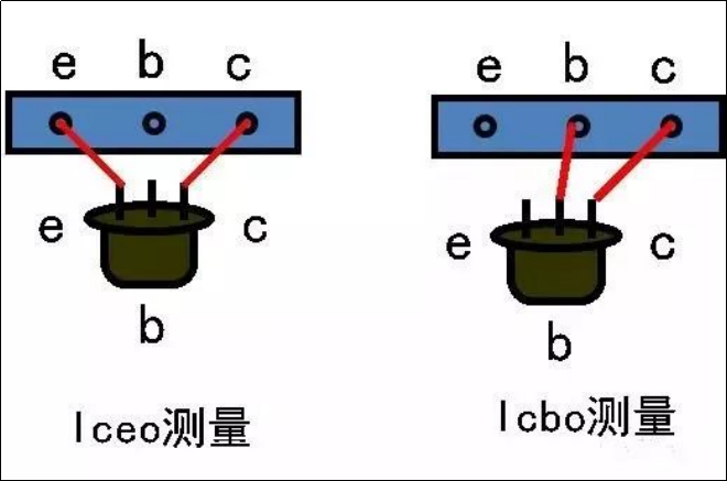
Measuring the Reverse Cut-off Current (Iceo, Icbo) of a Transistor:Iceo: The reverse cut-off current between the collector and emitter (base open). Icbo: The reverse cut-off current between the collector and base (emitter open).Set the switch to R×1K range, short the probes, and adjust the zero ohm potentiometer to make the pointer return to zero (the full-scale current value is approximately 90μA at this time).Separate the probes, insert the transistor being tested into the socket as shown, and the scale indicated by the pointer multiplied by 12 gives the approximate reverse cut-off current value of the transistor.If Iceo>90μA, use the R×100 range for measurement (the full-scale current value is approximately 900μA at this time).
Determining Diode Lead Polarity:A diode is a semiconductor device with significant unidirectional conductivity or nonlinear volt-ampere characteristics. Typically, the forward resistance of small power germanium diodes is 300~500Ω, while the reverse resistance is tens of kilohms; silicon diodes have a forward resistance of about 1kΩ or higher, and a reverse resistance above 500kΩ. The greater the difference in forward and reverse resistance, the better.Range Selection: When measuring, generally select R×1K or R×100 range; do not use R×1 or R×10K range. Using R×1 range may cause excessive current, potentially burning out the diode, while using R×10K range may apply too high a voltage, risking breakdown of the diode.Polarity Judgment: Connect the two probes to the two terminals of the diode, compare the resistance values measured in both directions; the terminal connected to the black probe is the positive terminal of the diode if the resistance value is smaller, because in the multimeter’s resistance measurement circuit, the red probe is connected to the negative terminal of the internal battery, and the black probe is connected to the positive terminal of the internal battery.

Capacitance and Inductance Measurement:Capacitance Measurement: Refer to the diagram for measurement method, select the C.L.dB (10V AC) range, and read the capacitance measurement value on the C(μF) 50Hz scale.Inductance Measurement: Refer to the diagram (replace capacitance with inductance), select the C.L.dB (10V AC) range, and read the inductance measurement value on the L(H) 50Hz scale.
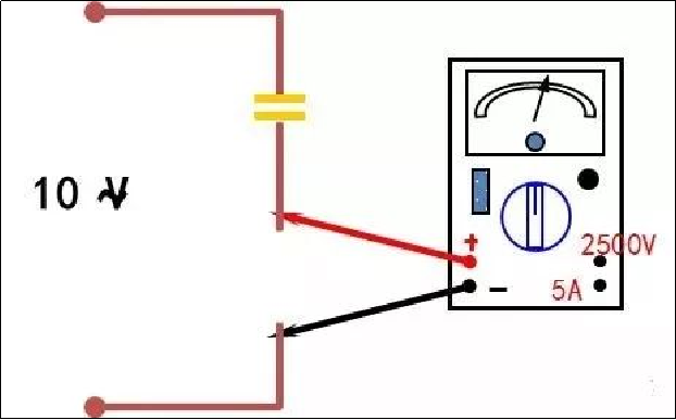
Precautions for Using a Multimeter:Before using a multimeter, one must be familiar with the operation methods, measurement principles, types of measurements, and ranges, and verify that the selector switch and sockets are correct.The multimeter must be placed horizontally during use, and mechanical zeroing should be performed before use.After measurement, set the range selector switch to the highest position to prevent accidental damage to the meter during the next measurement.For multimeters that are not used for a long time, the battery should be removed to avoid deterioration and leakage that could damage the circuit board.When measuring voltage in circuits with inductive reactance, the multimeter must be disconnected before cutting off the power to prevent damage to the voltmeter from high voltage generated by self-induction.